Table of Contents
Advertisement
Owner's Manual
Mini Multimeter
with Non-Contact
Voltage Detector
(NCV)
Model No.
82315
CAUTION: Read, understand and
follow Safety Rules and Operating
Instructions in this manual before
using this product.
© Sears, Roebuck and Co., Hoffman Estates, IL 60179 U.S.A.
www.craftsman.com
• Safety
• Operation
• Maintenance
• Español
080706
Advertisement
Table of Contents

Related Manuals for Craftsman 82315


Summary of Contents for Craftsman 82315
- Page 1 Owner’s Manual Mini Multimeter with Non-Contact Voltage Detector (NCV) Model No. 82315 • Safety CAUTION: Read, understand and • Operation follow Safety Rules and Operating Instructions in this manual before • Maintenance using this product. • Español © Sears, Roebuck and Co., Hoffman Estates, IL 60179 U.S.A.
-
Page 2: Table Of Contents
TABLE OF CONTENTS Warranty.................... 3 Safety Instructions ................4 Safety Symbols ................. 5 Controls And Jacks................6 Display Symbols And Annunciators ..........7 Specifications ..................8 Battery Installation ................13 Operating Instructions ..............14 Non-Contact AC Voltage Detector ..........15 AC Voltage Measurements............ -
Page 3: Warranty
ONE YEAR FULL WARRANTY ONE YEAR FULL WARRANTY ON CRAFTSMAN MULTIMETER If this CRAFTSMAN Multimeter fails to give complete satisfaction within one year from the date of purchase, RETURN IT TO THE NEAREST SEARS STORE OR OTHER CRAFTSMAN OUTLET IN THE UNITED STATES, and Sears will replace it, free of charge. -
Page 4: Safety Instructions
SAFETY INSTRUCTIONS This meter has been designed for safe use, but must be operated with caution. The rules listed below must be carefully followed for safe operation. NEVER apply voltage or current to the meter that exceeds the specified maximum: Input Protection Limits Function Maximum Input... -
Page 5: Safety Symbols
SAFETY SYMBOLS This symbol adjacent to another symbol, terminal or operating device indicates that the operator must refer to an explanation in the Operating Instructions to avoid personal injury or damage to the meter. This WARNING symbol indicates a potentially WARNING hazardous situation, which if not avoided, could result in death or serious injury. -
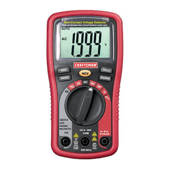
Page 6: Controls And Jacks
CONTROLS AND JACKS 1. AC Voltage Detector Sensor 2. AC Voltage Detector indicator light 3. LCD display 4. RELATIVE push- button 5. MODE button 6. Non-contact AC Voltage Detector test button 7. Rotary function dial 8. 10 ampere test lead jack 9. -
Page 7: Display Symbols And Annunciators
DISPLAY SYMBOLS AND ANNUNCIATORS •))) Continuity Diode test Battery status nano (10 ) (capacitance) micro (10 ) (amps, cap) milli (10 ) (volts, amps) Amps kilo (10 ) (ohms) Farads (capacitance) mega (10 ) (ohms) Ohms Hertz (frequency) Volts Percent (duty ratio) Relative Alternating current AUTO Autoranging... -
Page 8: Specifications
SPECIFICATIONS Function Range Resolution Accuracy Non-contact 100 to Resolution & accuracy do not apply AC Voltage 600VAC since the meter does not display the detector voltage in this mode. The lamp at the top of the meter’s display flashes when voltage is sensed and an audible warning will sound. - Page 9 Resistance 400! 0.1! ±(1.2% reading + 4 digits) 40k! 0.01k! ±(1.2% reading + 2 digits) 400k! 0.1k! 0.001M! 40M! 0.01M! ±(2.0% reading + 3 digits) 0.001nF ±(3.5% reading + 40 digits) Capacitanc 40nF 0.01nF 400nF 0.1nF ±(2.5% reading + 4 digits) 4µF 0.001µF ±(3.5% reading + 4 digits)
- Page 10 NOTES: Accuracy specifications consist of two elements: • (% reading) – This is the accuracy of the measurement circuit. • (+ digits) – This is the accuracy of the analog to digital converter. Accuracy is stated at 65 F to 83 F (18 C to 28 C) and less than...
- Page 11 Storage Humidity <80% RH Operating Altitude 7000ft. (2000meters) maximum. Weight 9.17 oz (260g) (includes holster). Size 5.8” x 2.9” x 1.6” (147 x 76 x 42mm) (includes holster) Approvals UL, CE Safety This meter is intended for indoor use and protected, against the users, by double insulation per EN61010-1 and IEC61010-1 2nd Edition (2001) to CAT II 1000V &...
- Page 12 Note – Examples include electricity meters and primary over- current protection equipment...
-
Page 13: Battery Installation
BATTERY INSTALLATION WARNING: To avoid electric shock, disconnect the test leads from any source of voltage before removing the battery cover. 1. Disconnect the test leads from the meter. 2. Remove the rear battery cover by removing the two screws using a Phillips head screwdriver. -
Page 14: Operating Instructions
OPERATING INSTRUCTIONS WARNING: Risk of electrocution. High-voltage circuits, both AC and DC, are very dangerous and should be measured with great care. 1. ALWAYS turn the function switch to the OFF position when the meter is not in use. 2. Press the HOLD button to freeze a displayed reading NOTE: On some low AC and DC voltage ranges, with the test leads not connected to a device, the display may show a random, changing reading. -
Page 15: Non-Contact Ac Voltage Detector
NON-CONTACT AC VOLTAGE DETECTOR The EX330 can detect the presence of AC voltage (from 100 to 600VAC) simply by being held very near to a voltage source. WARNING: Test the AC voltage detector on a known live circuit before each use. WARNING: Before using the meter in the AC Voltage Detector mode, verify that the battery is fresh by confirming characters appear on the LCD when the function dial is turned to any... -
Page 16: Ac Voltage Measurements
AC VOLTAGE MEASUREMENTS WARNING: Risk of Electrocution. The probe tips may not be long enough to contact the live parts inside some 240V outlets for appliances because the contacts are recessed deep in the outlets. As a result, the reading may show 0 volts when the outlet actually has voltage on it. -
Page 17: Dc Voltage Measurements
DC VOLTAGE MEASUREMENTS CAUTION: Do not measure DC voltages if a motor on the circuit is being switched ON or OFF. Large voltage surges may occur that can damage the meter. Set the function switch to the VDC position. Insert the black test lead banana plug into the negative COM jack. -
Page 18: Ac / Dc Current Measurements
AC / DC CURRENT MEASUREMENTS CAUTION: Do not make current measurements at 10 Amps for longer than 30 seconds. Exceeding 30 seconds may cause damage to the meter and/or the test leads. Insert the black test lead banana plug into the negative COM jack. -
Page 19: Resistance Measurements
RESISTANCE MEASUREMENTS WARNING: To avoid electric shock, disconnect power to the unit under test and discharge all capacitors before taking any resistance measurements. Remove the batteries and unplug the line cords. Set the function switch to the ! position. Insert the black test lead banana plug into the negative COM jack. -
Page 20: Continuity Check
CONTINUITY CHECK WARNING: To avoid electric shock, never measure continuity on circuits or wires that have voltage on them. Set the function switch to the position. Insert the black lead banana plug into the negative COM jack. Insert the red test lead banana plug into the positive ! jack. -
Page 21: Diode Test
DIODE TEST Set the function switch to position. Insert the black test lead banana plug into the negative COM jack and the red test lead banana plug into the positive jack. Use the MODE button to view the icon on the Auto Ranging display. -
Page 22: Capacitance Measurements
CAPACITANCE MEASUREMENTS WARNING: To avoid electric shock, disconnect power to the unit under test and discharge all capacitors before taking any capacitance measurements. Remove the batteries and unplug the line cords. Set the rotary function switch to the CAP position. Insert the black test lead banana plug into the negative COM jack. -
Page 23: Frequency Measurements
FREQUENCY MEASUREMENTS Use the MODE button to view the Hz unit of measure on the LCD display. Insert the black test lead banana plug into the negative COM jack and the red test lead banana plug into the positive Hz jack. -
Page 24: Contact Temperature Measurements
CONTACT TEMPERATURE MEASUREMENTS Set the function switch to the ºF or ºC position. Insert the Temperature Probe into the input jacks, making sure to observe polarity. The probe can be pressed against a device under test to read its temperature or the probe can be held in air to read the ambient temperature. -
Page 25: Auto-Manual Range Selection
AUTO-MANUAL RANGE SELECTION When the meter is first turned on, it automatically goes into the Auto Range mode. This automatically selects the best range for the measurements being made and is generally the best mode for most measurements. For measurement situations requiring that a range be manually selected, perform the following: Press the RANGE key. -
Page 26: Maintenance
MAINTENANCE WARNING: To avoid electric shock, disconnect the test leads from any source of voltage before removing the back cover or the battery or fuse covers. WARNING: To avoid electric shock, do not operate your meter until the battery and fuse covers are in place and fastened securely. -
Page 27: Low Battery Indication
LOW BATTERY INDICATION WARNING: To avoid electric shock, disconnect the test leads from any source of voltage before removing the battery cover. LOW BATTERY INDICATION icon will appear in the lower left-hand corner of the display when the battery voltage becomes low. Replace the batteries when this appears. -
Page 28: Battery Replacement
BATTERY REPLACEMENT Disconnect the test leads from the meter. Remove the protective rubber holster as shown in the diagram. Remove the Phillips head screw located on the lower back of the instrument. Flip up the fuse/battery compartment cover to access the batteries. -
Page 29: Replacing The Fuses
REPLACING THE FUSES WARNING: To avoid electric shock, disconnect the test leads from any source of voltage before removing the fuse cover. Disconnect the test leads from the meter. Remove the protective rubber holster as shown in the diagram. Remove the Phillips head screw located on the lower back of the instrument. -
Page 30: Troubleshooting
SERVICE AND PARTS Item Number Description 82374 Fuse kit 93894 9V battery 82378 Set of black and red Test Leads 82315-D Replacement battery cover 82315-C Front Cover 82315-CS Rear cover screws 82377 Thermocouple probe For replacement parts shipped directly to your home Call 9 am –...