Sony HVR-M35U Operating Instructions Manual
Digital hd videocassette recorder
Hide thumbs
Also See for HVR-M35U:
- Brochure & specs (20 pages) ,
- Limited warranty (7 pages) ,
- Brochure & specs (8 pages)

Related Manuals for Sony HVR-M35U


Summary of Contents for Sony HVR-M35U
- Page 1 3-276-290-11 (1) Digital HD Videocassette Recorder Operating Instructions Before operating the unit, please read this manual thoroughly, and retain it for future reference. HVR-M35U/M35N/M35E/M35P © 2008 Sony Corporation...
-
Page 2: Table Of Contents
Table of Contents Chapter 1 Overview Features...................... 4 Location and Function of Parts..............6 Front Panel ....................... 6 Rear Panel ...................... 16 Supplied Remote Commander ............... 23 Displaying Various Data................25 Chapter 2 Playback and Recording Notes on Power Supply and Video Cassettes ........30 Preparing the Power Supply................ - Page 3 Chapter 4 Dubbing to Other Equipment Using the i.LINK Jack, Duplication, Audio Dubbing, and Connecting a Computer Dubbing to Other Equipment Using the i.LINK Jack......59 Connections for Dubbing ................59 Dubbing Procedures..................60 Duplication (Generating a work tape with the same time code) ..61 Audio Dubbing ..................
-
Page 4: Chapter 1 Overview
Chapter Overview Features The HVR-M35U/M35N/M35E/M35P is a digital HD For details, see “Major Differences among HDV1080i, DVCAM, and DV Formats” on page 33. videocassette recorder supporting the HDV and DVCAM/DV formats. The unit produces stable, superior picture quality using digital processing and by Compatible with both interlaced and separating image signals into color difference signals progressive HDV recording/playback... - Page 5 Corporation. REC LEVEL, PHONE LEVEL control knobs, and a STATUS CHECK button. is a trademark of Sony Corporation and Victor Company of Japan, Ltd. All other product names mentioned here may be the trademarks or registered trademarks of their respective companies.
-
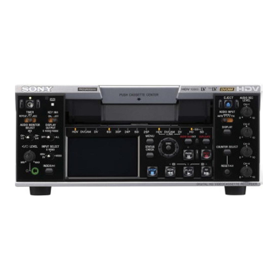
Page 6: Location And Function Of Parts
In addition to the Remote Commander supplied with the This indicator blinks while a cassette is being ejected. unit, the unit accepts signals from any Sony Remote For details, see “Inserting/Ejecting Cassettes” on page 31. Commander whose command mode is set to VTR4. - Page 7 Notes Notes • When the ON/STANDBY lamp is out, this switch does • During audio dubbing, if you want to listen to the not operate. Press the “|” (ON) marked side of the sound recorded on the tape, set this switch to CH-1/2; POWER switch on the rear panel before operating the if you want to listen to the sound being dubbed, set the ON/STANDBY switch.
- Page 8 Location and Function of Parts i INDEX (A1) button k Speaker (bottom panel) Press this button to write an index mark while recording. Use this speaker to monitor sounds in monaural during Indexing is useful when you search for scenes on a tape. recording or playback.
-
Page 9: Menu Button
1 Monitor display section 4 Indicator section (see page 14) 8 DISPLAY button 1 J/j/K/k buttons 2 MENU button 3 EXEC (execute) button 7 COUNTER SELECT 4 STATUS CHECK button button 6 RESET (Counter reset) (A3) button 5 LCD (Liquid Crystal 2 Tape transport Display) monitor control section... -
Page 10: Display Button
Location and Function of Parts f RESET (Counter reset) (A3) button h DISPLAY button Press this button when the count value of the counter is Use this button to change the text data displayed on the displayed. The count value is then reset to 0:00:00:00. LCD monitor or the text data output from the video Also, this button can be used as the ASSIGN (A3) jacks on the rear panel of the unit. - Page 11 2 Tape transport control section 1 AUDIO DUB (audio dubbing) (A2) button / indicator 2 DUPLICATE button / indicator 3 REC (record) button / indicator 4 FF (fast forward) button / indicator 5 PLAY button / indicator 6 REW (rewind) button / indicator 7 STOP button 8 PAUSE button / indicator a AUDIO DUB (audio dubbing) (A2) button /...
- Page 12 Location and Function of Parts c REC (record) button / indicator e PLAY button / indicator When you press and hold this button, then press the When you press this button, the indicator lights and PLAY button, each indicator lights and recording starts. playback begins.
- Page 13 3 Audio control section EJECT button (see qd in page 8) 1 AUDIO INPUT (AUTO/MANU/FIX) switch 2 AUDIO REC LEVEL control knob 1Monitor display section (see page 9) a AUDIO INPUT (AUTO/MANU/FIX) switch • If you input a sound at a level that exceeds the Switches the audio recording level adjustment mode.
- Page 14 Location and Function of Parts 4 Indicator section 7 50i indicator 8 25p indicator 6 24p indicator 9 HDV-i.LINK indicator 5 30p indicator q; DVCAM-i.LINK indicator 4 60i indicator qa DV-i.LINK indicator 3 DV indicator qs HD-SDI indicator 2 DVCAM indicator qd SD-SDI indicator 1 HDV indicator a HDV indicator...
- Page 15 e 30p indicator m SD-SDI indicator Lights when the unit is in either of the following Lights when the unit is in either of the following operating states. operating states. • When a tape recorded in 1080/30p format or 720/30p •...
-
Page 16: Rear Panel
Location and Function of Parts Rear Panel 1 MONITOR jacks q; LANC jack 9 HD/SD SDI OUT jack 2 AES/EBU OUT jacks 8 RESET button 3 TC OUT jack 7 CONTROL S jack HDV/DV jack 1 Video signal input/output 5 POWER switch section (see page 20) 4 AC IN connector 2 Audio signal input/output... - Page 17 e POWER (main power) switch • A video signal which is input from the HDV/DV jack The main power switch of the unit. When this switch is will be output directly to the HD/SD SDI OUT jack, in the “|” position, the ON/STANDBY lamp on the front the COMPONENT OUT jacks, the S VIDEO OUT panel lights up in green.
- Page 18 Location and Function of Parts • The unit is only compatible with standard video Notes signals. If you input the types of video signals shown • Signals are output to the HD/SD SDI OUT jack and below, recorded picture and sound may be distorted. COMPONENT OUT jack simultaneously.
- Page 19 • A LANC connection transmits command signals for playback, stop, pause playback, as well as the time code, tape counter, and data status of the unit. • Jacks labeled CONTROL L have the same function as LANC jacks. • There are some limitations when you edit an HDV- formatted tape.
- Page 20 Location and Function of Parts 1 Video signal input/output section 1 S VIDEO jacks 3 COMPONENT OUT jacks 2 VIDEO jacks a S VIDEO jacks Notes To connect a device equipped with S video jacks, use • When images are output in 720p format, some of the the S VIDEO jacks on the unit.
- Page 21 • The output level of the COMPONENT OUT jacks is as follows: Output at 480i (NTSC) With [BETACAM] selected in [480i LEVEL] of the [IN/OUT REC] menu Y: 1.0 Vp-p (with 0.286 Vp-p sync negative, output impedance 75 Ω (ohms), unbalanced) Pb/Cb/B-Y, Pr/Cr/R-Y: 0.7 Vp-p (output impedance 75 Ω...
- Page 22 Location and Function of Parts 2 Audio signal input/output section 1 INPUT LEVEL switch 2 AUDIO IN jacks 3 AUDIO OUT jacks a INPUT LEVEL (–10/–2/+4) switch c AUDIO OUT CH-1 to CH-4 jacks Select one from –10 dB, –2 dB, or +4 dB, according to Used to output audio signals (CH-1 to CH-4).
-
Page 23: Supplied Remote Commander
Supplied Remote Commander 1 EJECT button ql 1 button qk END SEARCH button 2 SEARCH SELECT buttons qj INDEX MARK button 3 Buttons for playing at qh SHUTTLE MAX button various speeds qg REW&PLAY button 4 MENU button 5 J/j/K/k button qf COUNTER SELECT button 6 EXEC button qd DATA CODE button... - Page 24 [WIRELESS] to enable the Remote Commander to control the unit. • In addition to the Remote Commander supplied with the unit, the unit accepts signals from any Sony Remote Commander with a command mode set to Note on batteries VTR4.
-
Page 25: Displaying Various Data
Displaying Various Data The unit can display various superimposed text data on Data display You can confirm important information for normal the built-in LCD monitor, and also on an external recording or playback, such as time code or remaining monitor connected to the unit. To display text data on an external monitor, set the DISPLAY OUTPUT switch to tape time, on the screen. - Page 26 Displaying Various Data i Time counter (time code/user bits/count value of n Black signal indicator the counter) indicator Displays a Black signal indicator when [COLOR BAR] Displays the count value of the counter, time code, or is set to [ON] and [TYPE] is set to [BLACK] in user bits.
- Page 27 STATUS CHECK screen 00:10:26:12 To display the STATUS CHECK screen, press the STATUS CHECK button. Each time you press the J/j button, the STATUS When the count value of the counter is negative, “–” CHECK screen switches in the order of AUDIO, appears as the first digit (leftmost digit).
- Page 28 Displaying Various Data The unit detects the audio mode as follows: When the AGC (Auto Gain Control) of a pair of In the playback mode: Detects the audio mode channels is linked, this symbol is placed between the recorded on the tape. channels.
- Page 29 ASSIGN screen The ASSIGN screen is displayed when STATUS CHECK screen is set to ASSIGN. You can confirm the setting values of [ASSIGN BTN] in the [OTHERS] menu. For details on ASSIGN buttons, see “ASSIGN BTN” in the “OTHERS” menu on page 83. ASSIGN ASSIGN INDEX MARK...
-
Page 30: Chapter 2 Playback And Recording
Chapter Playback and Recording Notes on Power Supply and Video Cassettes thirds of the time available when HDV/DV (SP) Usable cassettes recording is used. For recording in the HDV/DV format, we recommend you use a DigitalMaster™ cassette such as standard Cassette memory HDV/DVCAM/DV cassette (PHDV-276DM, etc.), or mini HDV/DVCAM/DV cassette (PHDVM-63DM). -
Page 31: Preparing The Power Supply
Checking the tape for slack Inserting/Ejecting Cassettes Using a paper clip or a similar object, turn the reel To insert a cassette gently in the direction shown by the arrow. If the reel does not move, there is no slack. After checking the tape for slack, hold the cassette so that the tape window is facing upward, then insert it into the unit. -
Page 32: Notes On Playback/Recording
The unit can play back pictures recorded in x.v.Color. When the cassette you play back on the unit contains • x.v.Color is a brand name that Sony is proposing as a copyright signals, you cannot copy it to a tape in another device connected to your unit. -
Page 33: Recording Format And Input/Output Signals
Recording Format and Input/Output Signals Major Differences among HDV1080i, DVCAM, and DV Formats (This unit and other equipment for professional use may be functionally extended. For details, see the notes below the table.) Specification HDV1080i DVCAM DV (SP) Track pitch 10 µm 15 µm 10 µm... -
Page 34: Recording Input Signals And Recording Formats
Recording Format and Input/Output Signals Digital signal output section a: Output, —: No output or N/A SDI output i.LINK output Digital audio output DV (DVCAM/ AES/EBU Output signal HD/SD SDI AES/EBU HDV/DV HDV/DV Output jack Input signal Input jack Analog signal VIDEO/S VIDEO —... -
Page 35: Playback Tape Format And Output Signals
Playback Tape Format and Output Signals Analog signal output section a: Output, —: No output or N/A Analog video output Analog audio output Output signal VIDEO/ COMPONENT AUDIO OUT AUDIO OUT Output jack S VIDEO Format of the signals recorded on the tape DVCAM DV (SP) 1080/60i... - Page 36 Recording Format and Input/Output Signals Digital signal output section a: Output, —: No output or N/A SDI output i.LINK output Digital audio output DV (DVCAM/ AES/EBU Output signal HD/SD SDI AES/EBU HDV/DV HDV/DV Output jack Format of the signals recorded in the tape DVCAM —...
-
Page 37: Playback
Playback This section describes the connections and settings for When you connect the unit to a monitor compatible with playback and functions such as playback at various SDI audio using an SDI cable, audio cable connection is speeds, and searching for a specific scene on a recorded not needed. - Page 38 Playback Notes Connecting the unit to a monitor equipped with an i.LINK jack • To playback an image recorded in HDV format when you connect the monitor using an SDI cable or a The video and audio signals are sent with hardly any component video cable, set [SDI/CMPNT] of [VIDEO degradation, enabling high-quality playback to a OUT] in the [IN/OUT REC] menu according to the...
-
Page 39: Settings For Playback
• If you connect the input connectors of the unit to the [DOWN CONVERT] of [VIDEO OUT] in the [IN/ output connectors of a monitor, a humming noise may OUT REC] menu to the desired mode (page 73). be generated or the image may be distorted. If these Power on the monitor, then set the monitor’s input phenomena occur, use the INPUT SELECT switch to switch according to the signals input. -
Page 40: Playback Functions
Displaying information (data codes) recorded on a tape If you record on a tape using a Sony digital HD video camera recorder or digital camcorder, the recording information (data codes) is recorded on the tape. During playback, you can check the recording date and time from the data codes by displaying this information on the unit. - Page 41 ×1/5 button on the Remote Commander while pointing it toward the unit, the playback speed Notes turns to 1/3 of normal speed. • When the command mode of a Sony device/remote commander is set to VTR4: (Continued) Chapter 2 Playback and Recording...
- Page 42 DSR-25/45/50, see “Cassette memory” on page 30. • Searching may not be done correctly if the tapes were not recorded on Sony-brand digital video equipment. (The search screens are displayed only on Data display screen.) Using PB ZOOM When PB ZOOM is assigned to an ASSIGN button, you can magnify pictures from about 1.1 to 5 times the...
-
Page 43: Auto Repeat (Custom Repeat)
When you press the ASSIGN button to which PB REPEAT CYCLE ON/OFF : Selects either to enable or disable the ZOOM is assigned, magnification mode starts and you can adjust the magnification with the J/j button. REPEAT CYCLE setting. When you press the EXEC button during magnification CYCLE : Sets the time of intervals for playback. - Page 44 Playback Set the TIMER switch on the front panel of the unit To start CUSTOM REPEAT to REPEAT. When [START TIME] is set to [OFF] Set the start time on the external AC timer. Set the TIMER switch to REPEAT. At the preset time, the power of the unit turns on, and after a few to several tens of seconds, auto s is displayed on the Data display screen (page...
-
Page 45: Edge Crop Marker
By using CUSTOM REPEAT, you can do the EDGE CROP MARKER following (example) The unit allows you to adjust the edge crop position Repeat playback at 30 minute intervals: under the following conditions: – When you output down converted HDV 16:9 wide Set [ON/OFF] of [REPEAT CYCLE] to [ON]. -
Page 46: Marker Burn
Playback • To output an edge cropped picture by down converting • When you set [MARKER BURN] and [ALLSCAN the HDV-formatted picture to 4:3, see “VIDEO OUT” MODE] in the [DISPLAY SET] menu to [ON] at the (page 73) and “i.LINK SET” (page 74) in the “IN/ same time, the marker will not appear in the correct OUT REC”... -
Page 47: Using The Unit As A Videocassette Recorder
Using the Unit as a Videocassette Recorder This section describes the connections, settings and operations necessary to perform recording on the unit. The same settings and operations apply when you are using the unit for dubbing. Notes • For connection of editing devices, refer to the instruction manual of the editing controller and that of the editing software you use. - Page 48 Using the Unit as a Videocassette Recorder Notes Monitor HVR-M35 (rear panel) • If you connect the output connectors of the unit to the input connectors of the player, a humming noise may be generated or the image may be distorted. If these phenomena occur, set the INPUT SELECT switch to a position where a signal is not currently being input, or disconnect the cables.
-
Page 49: Settings For Recording
• With an HDV/DV connection, data codes (recording Settings for Recording date/time, camera data) recorded on the source tape are transmitted to the recorder (the unit). As a result, when you play back a recorded tape on the unit and press the Preparation on the recorder (the unit) DATA CODE button on the Remote Commander, the same data codes as those recorded on the source tape... - Page 50 Using the Unit as a Videocassette Recorder • When the signals are input through the i.LINK Note interface, the unit detects the field frequency of the When signals are input from the HDV/DV jack, the input signal automatically. You do not need to change audio mode is the same as the one used to input signals the [60i/50i SEL] setting.
-
Page 51: Recording Procedures
Recording Procedures Recording Functions This section describes the procedures used to record Marking an index signals sent from another VCR to the unit. For details on operation when the unit is connected to a By pressing the INDEX button on the unit or the computer via the HDV/DV jack, refer to “Editing (Connecting a Computer)”... - Page 52 Using the Unit as a Videocassette Recorder If the tape ends before the recording source AC timer recording stops operation The tape stops. By connecting the unit to an external AC timer (not supplied), you can start recording at a preset time. To stop recording during timer recording Make sure that the POWER switch on the rear panel of Press the STOP button on the unit.
-
Page 53: Chapter 3 Utilizing The Time Code
Chapter Utilizing the Time Code Setting the Time Code and User Bits The unit can set, display, record and play back the time For details on the menu, see “Chapter 5 Adjusting and Setting Through Menus” on page 70. code and user bits. Notes To set the initial time code value •... - Page 54 Setting the Time Code and User Bits Press the J/j buttons to select [TC/UB SET], then To set the value of the user bits press the EXEC button. You can set the user bits as eight-digit hexadecimal The following menu list is displayed. values (base 16) to have the date, time, scene number, and other information inserted into the time code track.
- Page 55 Press the J/j buttons to select [PRESET], then Notes press the EXEC button. • When this item is set to [EXTERNAL], the time code The following menu is displayed. input via the HDV/DV jack and the user bits set in [UB PRESET] are recorded.
- Page 56 Setting the Time Code and User Bits Note To switch the time code output when playing at various speeds (JOG) If you set the advancement mode to [FREE RUN], the time code will be updated by the internal clock while the Set [JOG TC OUT] in the [TC/UB SET] menu to unit’s power is off.
- Page 57 HVR-M35U/M35N/M35E/M35P time codes The unit has a HDV/DV jack. The time code displayed and recorded on the tape differs as shown below when the INPUT SELECT switch is set to HDV/ DV and when it is set to other than HDV/DV. [HDV/DV IN INPUT SELECT Mode...
-
Page 58: Time Code Output
Time Code Output Time code can be output from the TC OUT jack, HD/SD SDI OUT jack and/or the HDV/DV jack during playback/recording or in EE mode. Time code output during playback Time codes recorded on the tape are output. Time code output during recording or in EE mode Time codes generated by the time code generator of the... -
Page 59: Dubbing To Other Equipment Using The I.link Jack
Chapter Dubbing to Other Equipment Using the i.LINK Jack, Duplication, Audio Dubbing, and Connecting a Computer Dubbing to Other Equipment Using the i.LINK Jack This section describes the connections and settings Monitor necessary to perform dubbing on other equipment, using HVR-M35 (rear panel) the unit as a video player. -
Page 60: Dubbing Procedures
Dubbing to Other Equipment Using the i.LINK Jack There are some limitations to down converting a tape Dubbing Procedures recorded in HDV format to DVCAM format. For details, see “i.LINK SET” in the “IN/OUT REC” menu Prepare the unit. on page 74. Refer to “Settings for Recording”... -
Page 61: Duplication (Generating A Work Tape With The Same Time Code)
Duplication (Generating a work tape with the same time code) DUPLICATE PLUS is a dubbing function which image using a tape dubbed with DUPLICATE PLUS duplicates the tape with time codes through an i.LINK on the unit to a computer, we recommend you connection. - Page 62 Duplication (Generating a work tape with the same time code) Press the STOP button on the unit to stop the tape. To adjust the point where duplication starts, while While holding the DUPLICATE button down, press holding the DUPLICATE button down, press the the PLAY button on the unit.
- Page 63 Duplicating a series of tapes Detecting a blank portion during duplication While pausing duplication mode, you can change the tape on the player. Therefore, you can duplicate a series If the unit detects a blank portion on the source tape of tapes on a single tape.
- Page 64 Clean the video heads with the supplied cleaning cassette (see page 95). Use a cleaning cassette. Note When a warning message other than those above is displayed, consult your Sony dealer. Chapter 4 Dubbing to Other Equipment Using the i.LINK Jack, Duplication, Audio Dubbing, and Connecting a Computer...
-
Page 65: Audio Dubbing
Audio Dubbing You can record just the sound on a recorded tape. (Audio dubbing) Notes • You can dub the sound onto a DVCAM-formatted tape recorded in the 32 kHz audio mode (4-channel/ 12 bits) only. You cannot dub the sound on a tape in the 48 kHz audio mode (2-channel/16 bits). - Page 66 Audio Dubbing To pause audio dubbing Dubbing sound Press the PAUSE button. Pressing the PAUSE button again resumes audio Connect the AUDIO INPUT jack of the unit and the dubbing. sound source using a phono jack cable (not supplied). To stop audio dubbing Press the STOP button.
-
Page 67: Editing (Connecting A Computer)
Editing (Connecting a Computer) You can set up an editing system by connecting the unit Notes to a computer (editing machine) using the HDV/DV • Be sure to connect the i.LINK cable to the computer jack (i.LINK connection) on the unit. The unit can (editing machine) first and then connect it to the unit. -
Page 68: Preparations
Editing (Connecting a Computer) • If your editing software has the capability to output the Preparations time code as well as the video and audio signals to the unit, and you intend to record that time code, set Transferring picture data from the unit to a [HDV/DV IN TC] in the [TC/UB SET] menu of the unit to [EXTERNAL]. - Page 69 Transferring picture data from a computer (editing machine) to the unit • To transfer picture data recorded on a tape to an editing machine in HDV (page 72), set [HDV/DV SEL] in the [IN/OUT REC] menu to [HDV], then set [HDV t DV CONV] of [i.LINK SET] in the [IN/OUT REC] menu to [OFF] (page 74).
-
Page 70: Chapter 5 Adjusting And Setting Through Menus
Chapter Adjusting and Setting Through Menus Operating Menus The unit allows you to set various parameters in the Changing a menu setting menus. Before you start using the unit, set the internal clock in [CLOCK SET] in the [OTHERS] menu. Except Press the MENU button. -
Page 71: Menu Structure
Menu Structure The menu of the unit consists of the following menus and submenus. IN/OUT REC HDV/DV SEL (page 72) REC MODE (page 72) VIDEO OUT (page 73) i.LINK SET (page 74) CROP ADJUST (page 74) CROP MARKER (page 75) COLOR BAR (page 76) EE/PB SEL (page 77) 480i LEVEL (page 77) -
Page 72: Menu Contents
Operating Menus Menu Contents Initial settings are indicated with rectangles. IN/OUT REC menu Icon/Menu Submenu Setting IN/OUT HDV/DV SEL Normally, set this menu to [AUTO]. Select this menu when you want to limit the output format (pages 38, 48, during tape playback or limit the signals to be input or output from the HDV/DV jack. - Page 73 Icon/Menu Submenu Setting IN/OUT VIDEO OUT Selects the mode of the video output jacks. SDI/CMPNT Selects the output format from the HD/SD SDI OUT jack and COMPONENT OUT jacks. Select from [480i], [480p/480i], [1080i/480i], or [720p/480i] when [60i/50i SEL] in the [OTHERS] menu is set to [60i].
- Page 74 Operating Menus Icon/Menu Submenu Setting IN/OUT i.LINK SET Adjusts the down conversion format. This menu is available when [HDV/DV SEL] is set to (pages 45, 67) [AUTO] or [HDV]. HDV t DV CONV BOFF : Disables down conversion. DVCAM : Down converts to DVCAM format.
- Page 75 Icon/Menu Submenu Setting IN/OUT CROP Selects whether to display EDGE CROP MARKER or not. MARKER BOFF : Does not display the crop marker. (page 45) ON : Displays the crop marker. Notes • This setting is only available when [DOWN CONVERT] or [DV WIDE CONV] of [VIDEO OUT], or [DOWN CONVERT] of [i.LINK SET] in the [IN/OUT REC] menu is set to [EDGE CROP].
- Page 76 Operating Menus Icon/Menu Submenu Setting IN/OUT COLOR BAR COLOR BAR Selects whether to display color bars or not. Also, you may select color bars with or without tone signals (1 kHz full bit –20 dB at 60i, 1 kHz full bit –18 dB at 50i). BOFF : Does not display color bars and no tone signals.
- Page 77 Icon/Menu Submenu Setting IN/OUT EE/PB SEL Sets the stop, fast-forward, and rewind modes. (page 11) BEE : Outputs EE picture and EE sound. PB : Mutes the image and sound. Note If this item is set to PB, the output from the unit will be as follows when you press any of the REC, DUPLICATE, or AUDIO DUB buttons separately when the unit is stopped (unless the cassette has been write-protected).
- Page 78 Operating Menus Icon/Menu Submenu Setting DISPLAY MARKER Selects whether to output MARKER BURN or not. BURN BOFF : Does not output MARKER BURN. (page 46) ON : Outputs MARKER BURN. Note There are some limitations to the output of MARKER BURN. For details, see page 46. ALLSCAN Zooms out the image on the LCD monitor to check the area surrounding the picture frame MODE...
-
Page 79: Audio Set Menu
AUDIO SET menu Icon/Menu Submenu Setting AUDIO SET AUDIO MODE Selects the audio mode. (page 27) BFS32K : Switches the audio mode to 4-channel mode (12-bit mode). FS48K : Switches the audio mode to 2-channel mode (16-bit mode). (This setting records the sound in all audio ranges, providing a high-quality sound recording.) Notes... - Page 80 Operating Menus VTR SET menu Icon/Menu Submenu Setting VTR SET DUPLICATE Selects the video format and whether or not to use auto rewind during duplication. PLUS FORMAT SEL (page 61) BALL : Duplicates all video formats. HDV1080 : The player automatically detects only 1080 HDV (both interlaced and progressive) and duplicates.
- Page 81 Icon/Menu Submenu Setting VTR SET STILL TIME Selects the time to switch to the tape protection mode from the still mode. B30sec : 30 seconds 1min : 1 minute 2min : 2 minutes 3min : 3 minutes Notes • If the unit is left in the playback pause mode for a long time, the tape or the video heads may be damaged or the video heads may become clogged.
- Page 82 Operating Menus Icon/Menu Submenu Setting TC/UB SET HDV/DV IN TC Selects whether to record internal time code or external time code while the unit records (page 53) signals input from the HDV/DV jack. BINTERNAL : Records the time code generated by the internal time code generator. (If [TC MAKE] is set to [REGENERATE] and no time code is recorded on the tape, the unit records time code from 00:00:00:00.
-
Page 83: Others Menu
CONTROL S jack. (The Remote Commander is disabled.) Notes • The unit accepts signals from any Sony Remote Commander with its command mode set to VTR4, not only the supplied one. To disable operation from any Remote Commander, set this item to CONTROL S. - Page 84 Operating Menus Icon/Menu Submenu Setting OTHERS PB YNR Selects the noise reduction level for the luminance signals when a tape is played. BOFF : No noise reduction LOW : Low noise reduction HIGH : High noise reduction Notes • When you use noise reduction, there may be an afterimage depending on the condition of the picture.
- Page 85 Icon/Menu Submenu Setting OTHERS 60i/50i SEL Switches between 1080/60i (NTSC) and 1080/50i (PAL). (page 49) 1 Press the J/j buttons to select [YES], then press the EXEC button. 60i/50i SEL Change to 50i? Reboots after change. 2 Press the J/j buttons to select [YES] again, then press the EXEC button. You can save the setting values for the unit in the internal memory as VCR profiles.
-
Page 86: Chapter 6 Maintenance
LCD monitor. The unit operates by itself. • [COMMANDER] in the [OTHERS] menu is set to [WIRELESS] and a Sony Remote Commander with its command mode set to VTR4 is operating near the unit. -
Page 87: Power Sources
Symptom Cause/Remedy Whenever you connect the unit to an AC • [AC ON MODE] in the [OTHERS] menu is set to [ON]. outlet, the unit turns on automatically. t Set [AC ON MODE] to [STANDBY]. • There is a cassette inside the unit and the TIMER switch is set to REPEAT or REC. - Page 88 Troubleshooting Symptom Cause/Remedy A cassette tape cannot be removed. t Check whether the power supply is connected properly. The cassette tape is not ejected when you • Moisture condensation has occurred in the unit (page 97). press the EJECT button. The cassette memory data and title are not •...
- Page 89 Symptom Cause/Remedy A user bit is not displayed correctly during • When input video signals without a user bit are recorded while HDV is input via fast-forward/rewind. i.LINK, the user bit is not displayed correctly. Either “– – – – – –” or “00 00 00 00” is displayed during playback and fast-forward/rewind, respectively.
- Page 90 Troubleshooting Symptom Cause/Remedy When the tape is rewound to its beginning, • The TIMER switch is set to REPEAT. the playback automatically starts. t Set the TIMER switch to OFF. • You pressed the PLAY button while holding the REW button down. t If you do this, the unit rewinds the tape to its beginning and begins playback (page 12).
- Page 91 Symptom Cause/Remedy The output from the S VIDEO OUT jack The output from the S VIDEO OUT jack and the VIDEO OUT jack is set as follows. and VIDEO OUT jack is different from the • When the playback format is set as shown below, the output from the S VIDEO [DOWN CONVERT] setting of [VIDEO OUT jack or VIDEO OUT jack is fixed to EDGE CROP.
- Page 92 Troubleshooting Symptom Cause/Remedy When you set the INPUT LEVEL switch: Confirm the level of the sound output from the player by referring to the player’s • You do not know how to adjust the input instruction manual. According to that output level, set the INPUT LEVEL switch on the rear panel of the unit so as to obtain an optimum level.
-
Page 93: Warning Indicators And Messages
C:ss:ss/E:ss:ss (Self-diagnosis If an error still recurs after you retry the corrective action several times, contact display) Sony Customer Service or your place of purchase. C:21:ss t Condensation has occurred. Remove the cassette and insert it again after approximately 1 hour (page 97). -
Page 94: Alarm Messages
Warning Indicators and Messages Alarm Messages The following alarm messages will appear together with the alarm indicators. Take corrective action according to the displayed message. Item Message Cause/Corrective Action t See page 97 for details. Moisture % Z Moisture condensation. Eject the cassette. condensation t See page 97 for details. -
Page 95: Notes On Use
Notes on Use To prevent electromagnetic interference Notes on the Videocassette caused by radio communication equipment Recorder such as cellular phones, transceivers, etc. The use of radio communication equipment such as Do not use the unit in a place subject to direct cellular phones or transceivers near the unit may cause sunlight or heat sources a malfunction and can affect the audio/video signals. -
Page 96: Notes On The Video Cassettes
• mosaic-pattern noise appears on the playback picture. case, you have to replace the video heads with new ones. • the playback picture freezes. Please consult your Sony dealer. • a part of the playback picture does not move. • playback pictures do not appear. -
Page 97: Notes On The Lcd Screen
Cleaning the terminal About Moisture Condensation If the gold-plated terminals of a cassette become dirty, or dirt accumulates on the terminals, the correct If the unit or cassette is brought directly from a cold to remaining tape time may not be displayed. a warm location, moisture may condense inside or Clean the terminal with a swab once every ten times outside the unit or tape. -
Page 98: Digital Hours Meter
The rechargeable Use them as guidelines for scheduling maintenance. In battery is charged as long as the unit is operated. If the general, consult your Sony dealer about necessary period the unit is operated is short, the battery periodic maintenance checks. -
Page 99: Appendix
Appendix Notes on Dubbing Dubbing with the S VIDEO or VIDEO jacks When you use the unit as a recorder to perform dubbing between the unit and other equipment using the S VIDEO jack and the VIDEO jack, the format to be used for recording is set according to the [ REC MODE] setting in the [IN/OUT REC] menu. - Page 100 Notes on Dubbing Dubbing with the HDV/DV jack When you perform dubbing between the unit and digital video equipment connected with an i.LINK cable using the unit as a player, the HDV/DV jack output format is determined in accordance with the playback tape format and menu setting of the unit.
- Page 101 Recording tape when the unit is used as a recorder Menu item i.LINK input format Recording tape format (AUDIO MODE) HDV/DV SEL REC MODE AUTO — HDV (LOCK MODE) — HDV (LOCK MODE) — No recording DVCAM AUTO DVCAM DVCAM (Complies with input signals) DV SP DV (Complies with input signals) —...
-
Page 102: About I.link
• i.LINK is an easy-to-remember term for the IEEE with an i.LINK jack using the i.LINK cable, power off 1394 standard proposed by Sony, and is a trademark the equipment and remove the power cord from the AC approved by many corporations in Japan and overseas. -
Page 103: Specifications
Specifications System Maximum input level: Video/Audio recording/playing head system –10: +18 dBu (approx. 6 Vrms) Rotating dual-head helical scan –2: +24 dBu (approx. 12.5 Vrms) Audio recording format (HDV) +4: +30 dBu (approx. 25 Vrms) MPEG-1 Audio Layer2 Analog audio output (2-channel) AUDIO OUT XLR type 3-pin, convexity ×... - Page 104 Specifications Chrominance signal: HD-SDI: 0.286 Vp-p (60i/NTSC) HD-SDI format, SMPTE292M (burst, 75 Ω (ohms)) AES/EBU OUT jack 0.3 Vp-p (50i/PAL) BNC type × 2 (burst, 75 Ω (ohms)) AES-3id-1995 COMPONENT OUT jacks TC OUT jack BNC type BNC type × 1 Output at 480i NTSC 2.2 Vp-p, 600 Ω...
- Page 105 Dimensions Approx. 212 × 98 × 390.3 mm × 3 × 15 inches) (w/h/d, including projecting parts and controls) 212 (8 3/8) 175 (7) Unit: mm (inches) Mass Approx. 4.4 kg (9 lb. 12 oz.) Supplied accessories Remote Commander (1) Power cord (1) Cleaning cassette (1) Operating Instructions (1)
-
Page 106: Index
Index For submenu items, see “Submenu Index” on page 108. Digital signal output during playback ......36 AC IN connector ......16 i.LINK..........102 in EE mode .......34 t HDV/DV jack Advancement mode......55 DISPLAY button ......10 AES/EBU .......... 5 IN/OUT REC menu ......72 DISPLAY OUTPUT switch ....8 AES/EBU jack......... - Page 107 STATUS CHECK screen....27 STOP button........12 ON/STANDBY switch...... 6 OTHERS menu ....... 83 Output signal during playback......35 TC OUT jack........16 in EE mode....... 33 TC/UB SET menu......81 Time code.........53 Output ........58 Selection ........55 PAUSE button ......... 12 Timer..........52 PB ZOOM ......... 42, 83 TIMER switch........7 Phones jack........
-
Page 108: Submenu Index
Submenu Index Numerics 480i LEVEL ........77 LANGUAGE ........83 60i/50i SEL ........85 LCD BLACK ........78 LCD BRIGHT........78 LCD COLOR ........78 LETTER SIZE .........78 AC ON MODE........ 84 AGC CH1,2 ........79 AGC CH3,4 ........79 ALLSCAN MODE......78 MARKER BURN ......78 ASSIGN BTN ......... - Page 112 Printed on 70% or more recycled paper using VOC (Volatile Organic Compound)-free vegetable oil based ink. Printed in Japan...