Table of Contents
Advertisement
Advertisement
Table of Contents
Troubleshooting

Related Manuals for Bacharach INJECTOR CALIBRATOR CD3


Summary of Contents for Bacharach INJECTOR CALIBRATOR CD3
- Page 1 INSTRUCTION 67-9319 INJECTOR CALIBRATOR CD3 Part Number 67-7622 to 67-7627 Installation/Operation/Maintenance Rev. 8 – January, 1999 Bacharach, Inc. 621 Hunt Valley Circle, New Kensington, PA 15968-7074 Phone: 724-334-5000 • FAX: 724-334-5001 • Web: www.bacharach-inc.com Printed in U.S.A.
- Page 2 Seller at the factory of manufacture and shown to Bacharach Inc.’s reasonable satisfaction to have been defective; provided that written notice of the defect shall have been given by Buyer to Bacharach Inc. within one (1) year after the date of delivery of this Product by Bacharach, Inc.
-
Page 3: Table Of Contents
3.2.4 Mounting DD Injector Types 53, 71, and 92 ..........3-18 3.2.5 Mounting DD Injector Type 149 ..............3-21 3.2.6 Mounting DD Injector Type 8.2 Liter ............3-23 3.2.7 Testing ......................3-25 3.2.8 Unclamping ....................3-27 3.2.9 Removing Injectors and Shutting Down Calibrator ........3-28 Instruction 67-9319 Bacharach, Inc. - Page 4 5.11 Electrical Control Panel ..................5-18 5.12 Electrical Power System ..................5-20 5.13 Standard Calibrator Accessories ................5-24 5.14 Accessories for use with Cummins Injectors ............5-25 5.15 Accessories for use with DD Injectors ..............5-26 APPENDIX A Calibrator Audit Kit Instruction 67-9319 Bacharach, Inc.
- Page 5 /str. - Digital display resolution - 0.1 mm /str. - Measurement sampling - 50 or 100 strokes - Stroke counter - electronic/optical - Accuracy: + . 75% of reading or 1 mm /str. whichever is greater Instruction 67-9319 Bacharach, Inc.
- Page 6 (mechanical) and injectors (mechanical) manufactured by Diesel Technology Corporation for engine models 53, 71, 92, 92 marine, 149, and 8.2L. These accessories must be ordered separately. - Provision for hanging all accessories on pegboard inside lower doors. Instruction 67-9319 Bacharach, Inc.
-
Page 7: Introduction
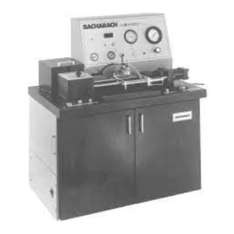
Detroit Diesel (DD) engine model numbers 53, 71, 92, 92 Marine, 149, and 8.2L. Figure 1-1. CD3 Injector Calibrator The CD3 was tested at the Bacharach factory with high precision instruments and calibrated for: • Injector supply pressure •... - Page 8 INTRODUCTION INJECTOR CALIBRATOR CD3 Figure 1-2. Console Features Feature Operation _____________________________________________________________________ START METER Button Switches on flowmeter. Lights while meter is running. (Flowmeter) / STROKE Four-digit LED display with resolution of 0.1 mm /stroke (Red Display (Flowmeter) flashing dot indicates update in LED display).
- Page 9 INJECTOR CALIBRATOR CD3 INTRODUCTION Feature Operation _____________________________________________________________________ CLAMP MONITOR Monitors the injector body-to-seat clamping force. When clamping BODY-TO-SEAT force is low, the indicator shows black. When clamping force is (Cummins) correct, the indicator shows green. PRESSURE Precision diaphragm-type pressure regulator allows the pressure of...
- Page 10 INTRODUCTION INJECTOR CALIBRATOR CD3 Feature Operation ___________________________________________________________________ “A” OR “B” Button There is no physical movement of the clamping mechanism when this button is pressed but it must be held down to operate the body to seat clamp or plunger to body clamp.
-
Page 11: Accessories
INJECTOR CALIBRATOR CD3 INTRODUCTION 1.2 Accessories Figure 1-5. Accessories The accessories for the CD3 come in three different sets. The Basic Accessories (not shown) supplied with. Accessories for the Cummins Injectors. Accessories for the DD Injectors. A lists of all parts in the accessories kits are given in Chapter 5. Accessories for testing Cummins or DD injectors are supplied if ordered separately. -
Page 12: Construction
INTRODUCTION INJECTOR CALIBRATOR CD3 1.3 Construction Cabinet: The frame is of welded steel 1-1/4 inch square tubing and angle iron. The upper left side and both front doors are easily accessible for changing speed, storing accessories, and performing routine maintenance through hinged doors. All other external panels are secured with 1/4-turn fasteners for easy removal. -
Page 13: Calibration Fluid System
INJECTOR CALIBRATOR CD3 INTRODUCTION Flywheel: A flywheel is mounted on the driven end of the camshaft for uniform rotation. An encoder wheel, also mounted on the camshaft in conjunction with an optical pickup, counts strokes. Cambox: The cambox is constructed of cast iron and contains a 1-1/2 inch diameter camshaft supported by heavy duty tapered roller bearings. - Page 14 This equipment is avail- regulator (7) is in the line to maintain pressure to able from Bacharach in Audit Kit (67-7707). produce a clamping force of 380 ±10 pounds. When lever “B” on the operator’s table is in the...
- Page 15 INJECTOR CALIBRATOR CD3 INTRODUCTION Figure 1-11. Clamping Circuit When lever “B” on the operator’s table is in the Calibration fluid is drawn from the reservoir (1) UNCLAMP position, fluid is directed into the rod through an externally mounted suction filter (2) side of the cylinder to retract it for unclamping.
-
Page 16: Calibration Fluid Temperature Control System
INTRODUCTION INJECTOR CALIBRATOR CD3 Figure 1-12. Injector Supply Circuit (c) Flowmeter Circuit (Injector Output) Motion of the piston, mechanically connected to a (Figure 1-13) linear measurement device, produces signals which represent displaced volume. These signals and The flowmeter circuit begins at the discharge head signals generated by camshaft rotation are elec- which receives the injector output. -
Page 17: Pneumatic System
INJECTOR CALIBRATOR CD3 INTRODUCTION Figure 1-13. Flowmeter Circuit A temperature sensor, mounted in the reservoir, is filter, and gauge. The correct air pressure settings connected to a solid-state temperature controller, are made at the factory (and must be monitored by which either switches on the heaters or energizes the operator). - Page 18 INTRODUCTION INJECTOR CALIBRATOR CD3 Figure 1-14A. Intensifier Assembly Figure 1-14B. Pneumatic System Page 1-12 Instructions 67-9319 Bacharach, Inc.
-
Page 19: Installation
INJECTOR CALIBRATOR CD3 INSTALLATION 2.0 INSTALLATION 2.1 Selecting the Site Select an area where the calibrator will be level and on solid footing, plus convenient to shop air, cold water line, drain and electrical supply. Allow space around the unit for operation and maintenance. -
Page 20: Utility Connections
INSTALLATION INJECTOR CALIBRATOR CD3 2.3 Utility Connections Electrical 1 Nameplate 4 Motor Rotation Direction 1. First, check the nameplate on the calibrator for electrical data. The plate is located behind the door on the left side of the calibrator to the left (on top of frame angle) beneath the motor. -
Page 21: Filling Reservoirs
2. Through the dipstick port, fill reservoir to the “F” mark on the dipstick with new fluid. Use Bacharach part number 67-5598 (SAE J967). 3. After a few minutes, check for leaks. 4. Place a tag on the reservoir giving date it was filled. -
Page 22: Pre-Operation Checks
INSTALLATION INJECTOR CALIBRATOR CD3 Flowmeter Transducer 8. The flowmeter transducer reservoir is filled at the factory before shipping. If additional fluid is required, see Section 2.6. 2.5 Pre-operation Checks Before trying to operate the calibrator for the first time be sure to complete all the initial checks and start-up procedures given in Section 2.6. - Page 23 If additional oil is required, use SAE 30W motor oil (non-detergent). *If electrical power does not correspond to the data on the nameplate, consult the Bacharach factory. (Checklist continued on next page) Figure 2-14. Initial Checks - Cambox Oil Page 2-5 Instructions 67-9319 Bacharach, Inc.
-
Page 24: Start-Up
INSTALLATION INJECTOR CALIBRATOR CD3 CONDITION ____________________________________________ 10. The flowmeter cavity is filled _____ _____ with lube oil (10W30) to a level 3/8 inch from the bottom. Replenish if necessary. DO NOT OVERFILL. 11. The intensifier fluid reservoir _____ _____ is filled with oil. If additional oil is required, add SAE 10- W30 motor oil. -
Page 25: Repacking For Shipping
INJECTOR CALIBRATOR CD3 INSTALLATION Repacking for Shipping 1. Drain the calibration fluid reservoir from both drain valves. 2. Pack all the accessories listed in Section 5.2. Do not ship the calibrator with its accessories hanging on the door. 3. Disconnect all power and utilities. Drain water and blow out water lines by applying shop air pressure at the WATER OUT fitting. - Page 26 INSTALLATION INJECTOR CALIBRATOR CD3 NOTES Page 2-8 Instructions 67-9319 Bacharach, Inc.
-
Page 27: Operation
INJECTOR CALIBRATOR CD3 OPERATION 3.0 OPERATION Push Rod Lock Adapters Drain Hose 3.1 Cummins Injectors Cummins 189 cam (67-6370) is installed in the cambox at the factory. Other cams are packed with the Cummins accessories. A complete set of Cummins Accessories is supplied under part number 67-7633 (Figure 5-14). -
Page 28: Changing Speed
OPERATION INJECTOR CALIBRATOR CD3 ____________________________________________________________________________________ Cummins Accessory Part Number or Identification ____________________________________________________________________________________ Push Rod Drain Locating Injector Type Adapter Link Connection Cam* ------------------------------------------------------------------------------------------------------------------------------- Flanged, H-NH H-NH,J-C H-NH 67-6580 —— Flanged, J-C H-NH,J-C 67-6580 —— PTB, PTC 3/8 3/8 PTB-PTC PTB-C ——... -
Page 29: Changing Cams
INJECTOR CALIBRATOR CD3 OPERATION 5 Move to Pulley Position 3.1.3 Changing Cams The cam is secured in place on the tapered end of the camshaft by a 3/4 in. hex nut and a 3/4 in. plain washer, and is locked to the shaft by a key. -
Page 30: Inserting The Cummins Discharge Head
OPERATION INJECTOR CALIBRATOR CD3 3.1.4 Inserting Cummins Discharge Head Push Rod Extension Cummins Discharge Head 1. For all Cummins injectors, insert discharge head (67-7642) into the clamp cylinder socket, with the quick connect socket facing up. NOTE: When discharge heads are instal- led for the first time, wet the O-ring with calibration fluid for easier installation. -
Page 31: Mounting Cummins Type Ptd Cylindrical Injectors
INJECTOR CALIBRATOR CD3 OPERATION 3.1.5 Mounting Cummins Type PTD Cylindrical Injectors 1 Adapter 3 Locating Pin 1 PTD Injector Before mounting injectors, check in the cambox to be sure that the proper cam for the injector to be tested is mounted on the camshaft. (See Section 3.1.3) - Page 32 OPERATION INJECTOR CALIBRATOR CD3 CLAMP 3.1.5.2 Clamping Body to Seat 6. Lift the pulley cover to expose the camshaft pulleys and flywheel. 7. Rotate flywheel by hand until the white paint- ed area on the flywheel shows through the window (the barring tool inserted in a hole in flywheel can help in turning the flywheel).
- Page 33 INJECTOR CALIBRATOR CD3 OPERATION 15. Release the HOLD TO OPERATE button first Inlet Fuel Connector Toggle Clamp and then the CLAMP/UNCLAMP lever. The lever will return to the center position. For clamping to occur correctly, you must follow this sequence.
-
Page 34: Mounting Cummins Types Ptb And Ptc Cylindrical Injectors
OPERATION INJECTOR CALIBRATOR CD3 3.1.6 Mounting Cummins Types PTB and 1 Plunger and Spring 1 PTB (or PTC) Injector PTC Cylindrical Injectors Before mounting injectors, check cambox to be sure that the proper cam for the injector to be tested is mounted on the camshaft. - Page 35 INJECTOR CALIBRATOR CD3 OPERATION 3.1.6.2 Clamping Body to Seat BODY TO SEAT CLAMP 7. Lift the pulley cover to expose the camshaft pulleys and flywheel. 8. Rotate flywheel by hand until the white painted area on the flywheel shows through the window (barring tool inserted in a hole in the flywheel can help in turning the flywheel).
- Page 36 OPERATION INJECTOR CALIBRATOR CD3 16. Release the HOLD TO OPERATE button first Inlet Fuel Connector Fuel Arm and then the CLAMP/UNCLAMP lever. The lever will return to the center position. For clamping to occur correctly, you must follow this sequence.
-
Page 37: Mounting Flanged Injectors
INJECTOR CALIBRATOR CD3 OPERATION 3.1.7 Mounting Cummins Flanged Injectors Plunger Flanged Aapter and Spring Injector Before mounting injectors, check cambox to be sure that the proper cam for the injector to be tested is mounted on the camshaft. (See Section 3.1.3) Also make sure the Cummins discharge head has been installed. - Page 38 OPERATION INJECTOR CALIBRATOR CD3 9. Press the BODY TO SEAT CLAMP button. 9 BODY TO SEAT CLAMP The air cylinders will retract and clamp the injector. 10. Release the BODY TO SEAT CLAMP button when the BODY TO SEAT monitor turns green.
-
Page 39: Testing
INJECTOR CALIBRATOR CD3 OPERATION 17. Connect the fuel inlet connector (using a Teflon O-ring) to the injector inlet port (the inlet Flanged Injector Swing Back Fuel Arm orifice in the injector is visible). 18. Use the drain hose connector assembly (67- 6580) to connect to the injector return port. -
Page 40: Unclamping
OPERATION INJECTOR CALIBRATOR CD3 The reading is in mm /stroke, which is equivalent to 3 UNCLAMP /1000 strokes (cc/1000 strokes). During a test run, if a change over is made from 50 to 100 stroke setting, or vice versa, ignore the next reading 7. -
Page 41: Detroit Diesel (Dd) Injectors
INJECTOR CALIBRATOR CD3 OPERATION 3.2 Detroit Diesel (DD) Injectors Injector Manifold Front Holder Cams Blocks Supports Cummins 189 cam (67-6370) is installed in the cambox at the factory. A complete set of DD accessories is supplied under part number 67-7632 (Figure 5-15). The inside left front door of the calibrator has spaces designated for hanging DD accessories (Figure 3-32). -
Page 42: Changing Cams
OPERATION INJECTOR CALIBRATOR CD3 2. Open the hinged door on the left side of the calibrator to expose the lower pulleys. 3. Insert barring tool into roller link assembly. 4. Push down on the barring tool to raise the motor enough to shift the drive belt from one set of pulleys to the other. - Page 43 INJECTOR CALIBRATOR CD3 OPERATION Injector Cam P/N Cam ID 53, 71, 92 & 92 M 77-0610 53,71,92 67-6372 8.2L 77-0610 53,71,92 8. Fit the cam in place on the camshaft and make sure key in the cam is properly seated.
-
Page 44: Mounting Dd Injector Types 53, 71, And 92
(77-0613) can be positioned in either of two return ports, depending on whether the injector to be tested is offset or standard. As supplied by Bacharach, the barbed elbow drain fitting is in position for offset injectors. For standard injectors, install the fitting in the other port. - Page 45 INJECTOR CALIBRATOR CD3 OPERATION 3.2.4.3 Body to Seat Clamp 9 BODY TO SEAT CLAMP NOTE: The body-to-seat air clamping is not needed for DD injectors. To keep them out of the way, activate the air cylinders and leave them in clamped position during the test.
- Page 46 OPERATION INJECTOR CALIBRATOR CD3 15. Make sure the O-rings are in position in the manifold block connectors. 3.2.4.6 Fuel Inlet 16. Disconnect the fuel inlet hose from the fuel arm CLAMP at the quick disconnect. 17. Swing the fuel inlet arm back toward console.
-
Page 47: Mounting Dd Injector Type 149
INJECTOR CALIBRATOR CD3 OPERATION 3.2.5 Mounting DD Injector Type 149 Drain Manifold Discharge Fitting Block Head Injector Before mounting injectors, check cambox to be sure that cam 67-6372 (149) is mounted on the cam- shaft. 3.2.5.1 Manifold 1. Place push rod extension (67-5708) over the push rod. - Page 48 OPERATION INJECTOR CALIBRATOR CD3 The air cylinders will retract and clamp injector. Manifold Inlet 6 Flowmeter Tubing 11. Press the BODY TO SEAT CLAMP button. 12. Release BODY TO SEAT CLAMP button when the BODY TO SEAT monitor turns green.
-
Page 49: Mounting Dd Injector Type 8.2 Liter
INJECTOR CALIBRATOR CD3 OPERATION Discharge Head Injector Spacer Block 3.2.6 Mounting DD Injector Type 8.2 Liter Before mounting injectors, check cambox to be sure that cam 77-0610 (53, 71, 92, 92 Marine or 8.2 L) is mounted on the camshaft. - Page 50 OPERATION INJECTOR CALIBRATOR CD3 8. Press the BODY TO SEAT CLAMP button. The air cylinders will retract and clamp injector. Injector 8.2 Carriage rail 3.2.6.4 Injector 10. Install the injector into the injector holder by hand pushing until the mounting slots on both the injector and the holder are aligned.
-
Page 51: Testing
In particular, it has been determined that Master Injectors marketed by Kent Moore all read higher on the Bacharach CD3 Calibrator by the amount shown below. Therefore, when checking Master Injectors, the fuel output as read on the digital... - Page 52 Therefore, for a type 71 Master injector stamped as 72.0, correct delivery value (fuel output) should be 73.0-76.0 mm³/str on a Bacharach CD3 Calibrator. From the above it follows that when calibrating and/or checking injectors in service it is necessary to add the above numbers to the limits given by the manufacturer.
-
Page 53: Unclamping
INJECTOR CALIBRATOR CD3 OPERATION 3.2.8 Unclamping 3 UNCLAMP 1. Disconnect the fuel inlet. 2. Press & hold the HOLD TO OPERATE button. 3. While holding button down, move the CLAMP/ UNCLAMP lever to UNCLAMP position and let the hydraulic cylinder completely retract. - Page 54 OPERATION INJECTOR CALIBRATOR CD3 NOTES Page 3-28 Instructions 67-9319 Bacharach, Inc.
-
Page 55: Maintenance & Troubleshooting
Fluid must be changed when viscosity is above 3.1 centistokes (cst) at 100°F (38°C). NOTE: To check viscosity use Viscor Cup Bacharach P/N (77-0391), part of the CD3 Audit Kit (67-7707). 2 Reservoir drains Figure 4-3. Reservoir Drains... - Page 56 5. Through the dipstick port, fill the reservoir to the 6 Suction filter “F” mark on the dipstick with new fluid. Use Bacharach part number 67-5598 (SAE J967). Figure 4-4. Suction Filter 8 Final stage filter NOTE: It’s a good idea to fasten a tag to the reservoir giving the date the fluid was changed.
-
Page 57: Changing Cambox Oil
INJECTOR CALIBRATOR CD3 MAINTENANCE AND TROUBLESHOOTING 4.1.3 Changing Cambox Oil After three months or 120 hours of operation (see hour meter), whichever occurs first, (or if the oil becomes contaminated) drain the oil from the cambox and refill using the following procedure: 1. -
Page 58: Troubleshooting
MAINTENANCE AND TROUBLESHOOTING INJECTOR CALIBRATOR CD3 4.2 TROUBLESHOOTING 4.2.1 Charts TROUBLESHOOTING CHART FOR MECHANICAL PROBLEM Fault Possible Cause and Remedy _____________________________________________________________________________________________________ Plunger-to-body May lack unlocking pressure — Press HOLD TO OPERATE button and listen for valve clamp faulty reliefs (“putt” sound). - Page 59 INJECTOR CALIBRATOR CD3 MAINTENANCE AND TROUBLESHOOTING TROUBLESHOOTING CHART FOR ELECTRICAL PROBLEMS Fault Possible Cause and Remedy _________________________________________________________________________________ Motor trips off 1. Overload setting may be too low – Readjust (Section 4.3.5). 2. Improper line voltage – Verify that incoming line voltage meets specifications.
-
Page 60: Hydraulic System
MAINTENANCE AND TROUBLESHOOTING INJECTOR CALIBRATOR CD3 TROUBLESHOOTING CHART FOR ELECTRICAL PROBLEMS (cont.) Fault Possible Cause and Remedy _________________________________________________________________________________ Flowmeter displays 1. Connector to main P.C. board may be loose – Reconnect. all zeros; will not 2. Flowmeter limit switches may be tripped – Remove power and reposition piston display flow adapter block to center of cavity. -
Page 61: Replacing O-Ring In Fuel Arm
INJECTOR CALIBRATOR CD3 MAINTENANCE AND TROUBLESHOOTING 4.2.3 Replacing O-ring in Fuel Arm 4 O-ring If calibration fluid is leaking at the fuel arm: 1. Pull cotter pin. 2. Tilt back clamp arm. 3. Lift out fuel connector and turn over. (Do not lose spring and washer.) -
Page 62: Changing Fuses
MAINTENANCE AND TROUBLESHOOTING INJECTOR CALIBRATOR CD3 4.2.5 Changing Fuses F-1 (2 Amps): This fuse is in the main power circuit for all control circuits. If this fuse blows, the operator’s console will indicate the following: POWER Indicator (Red): HEATER Indicator (Amber):... -
Page 63: Checking Main Pc Board
INJECTOR CALIBRATOR CD3 MAINTENANCE AND TROUBLESHOOTING 4.2.6 Checking Main PC Board Between these terminals on the main P.C. board: Voltage should be: If not, probable cause is: ________________________________________________________________________________ 15 and 16 11 to 13 VAC Defective fuse F-2 or transformer T2. -
Page 64: Adjustments
Do not change the temperature gauge calibration without use of a special fixture and procedure. Bacharach supplies the procedure and special fixture as part of the CD3 Calibrator Audit Kit (PN 67-7707) 4.3.2 Air Pressure Regulator Adjustment Required air pressure is set at the factory to produce the proper clamping force by the air cylinders and the correct pressure for unlocking the hydraulic cylinder. -
Page 65: Adjusting Pulley Cover Interlock
INJECTOR CALIBRATOR CD3 MAINTENANCE AND TROUBLESHOOTING 4.3.3 Adjusting Pulley cover Interlock 1. Adjust pulley cover up or down so that when closed, the cover will push in the button on the pulley cover interlock. 2. Adjust latch, if necessary, so that cover closes completely and stays closed while calibrator is operating. - Page 66 MAINTENANCE AND TROUBLESHOOTING INJECTOR CALIBRATOR CD3 3. Open the hinged side door. 4. Remove the upper back panel. 5. Loosen the nuts holding the optical detector to cross bar, and remove it from the cross bar. 6. Match mark the gear pump bracket and the motor mounting plate.
-
Page 67: Replacing Push Rod Shear Pin
INJECTOR CALIBRATOR CD3 MAINTENANCE AND TROUBLESHOOTING CAUTION Before turning on main drive, make sure that the injector supply hose (with quick connect) is either connected to the fuel arm or is disconnected. Any other connection (for instance - to a manifold block when no injector is installed) can cause fluid to squirt everywhere. - Page 68 MAINTENANCE AND TROUBLESHOOTING INJECTOR CALIBRATOR CD3 NOTES Page 4-14 Instructions 67-9319 Bacharach, Inc.
-
Page 69: Illustrated Parts List
PARTS LISTS AND DIAGRAMS 5.0 ILLUSTRATED PARTS LIST These lists include most parts which may need re- placing under normal operating conditions. If other parts are needed, consult the Bacharach factory. INDEX Sect. Subject Page Console, Front and Side Views Console, Rear View Cabinet, Front &... -
Page 70: Console, Front And Side Views
PARTS LISTS AND DIAGRAMS INJECTOR CALIBRATOR CD3 5.1 Console, Front and Side Views Item* Description Part # ________________________________________________________________ P.C. board assembly 67-6910 gauge, clamp monitor 67-6525 switch, push button, blk. (S-5) 104-0524 switch, Push button (S-6) 104-0536 105** gauge, 0-200 psi, 4-1/2" dia 67-6334 106** dial thermometer, 40-100 °F (5-60 °C) - Page 71 INJECTOR CALIBRATOR CD3 PARTS LISTS AND DIAGRAMS 5.1 Console, Front and Side Views (Cont.) Page 5-3 Instructions 67-9319 Bacharach, Inc.
-
Page 72: Console, Rear View
PARTS LISTS AND DIAGRAMS INJECTOR CALIBRATOR CD3 5.2 Console, Rear View Item* Description Part # ________________________________________________________________ orifice 67-2395 lube oil, SAE 30 06-2553 grommet, rubber 05-4618 fuse, 5 amp, 250 V, buss mda-5 04-2715 fuse, 3AG, slow-blo, 0.4 amp, 250 V... -
Page 73: Cabinet, Front & Left Side View
INJECTOR CALIBRATOR CD3 PARTS LISTS AND DIAGRAMS 5.3 Cabinet, Front & Left Side View Item* Description Part # ________________________________________________________________ pneumatic control assembly, complete 67-6460 pneumatic control parts: solenoid valve, 3-way, NC 120VA 03-4232 filter/regulator with gage 07-1576 switch, pressure, Sigmanetic... - Page 74 PARTS LISTS AND DIAGRAMS INJECTOR CALIBRATOR CD3 5.3 Cabinet, Front & Left View (cont.) Page 5-6 Instructions 67-9319 Bacharach, Inc.
-
Page 75: Cabinet, Top View
INJECTOR CALIBRATOR CD3 PARTS LISTS AND DIAGRAMS 5.4 Cabinet, Top View Item* Description Part # ___________________________________________________________ gear pump 67-6902 surge chamber assembly 67-6626 surge chamber replacement parts: O-ring, 3" ID x 3-3/16 OD 05-5186 fuel line, .093x24 67-6619 intensifier assembly... - Page 76 PARTS LISTS AND DIAGRAMS INJECTOR CALIBRATOR CD3 5.4 Cabinet, Top View (cont.) Page 5-8 Instructions 67-9319 Bacharach, Inc.
-
Page 77: Operator's Table
INJECTOR CALIBRATOR CD3 PARTS LISTS AND DIAGRAMS 5.5 Operator’s Table Item* Description Part # _______________________________________________ fuel arm assembly 67-7638 fuel arm parts: O-ring 05-5018 O-ring 05-5112 cambox assembly (see Section 5.7) 67-7619 injector carrier plate assembly 67-6473 cylinder carriage plate assembly... - Page 78 PARTS LISTS AND DIAGRAMS INJECTOR CALIBRATOR CD3 5.5 Operator’s Table (cont.) Page 5-10 Instructions 67-9319 Bacharach, Inc.
-
Page 79: Optical Detector
INJECTOR CALIBRATOR CD3 PARTS LISTS AND DIAGRAMS 5.6 Optical Detector Item* Description Part # __________________________________________________ optical detector assembly 60-7000 __________________________________________________ *(based on drawings 67-7622S10R86) Page 5-11 Instructions 67-9319 Bacharach, Inc. -
Page 80: Cambox Assembly
PARTS LISTS AND DIAGRAMS INJECTOR CALIBRATOR CD3 5.7 Cambox Assembly Item* Description Part # ______________________________________________ pusher rod 67-5704 spring lower seat 67-5713 cam follower sleeve assembly 67-5716 cambox 67-6374 push rod guide 67-6417 tappet assembly 67-6418 spring 67-6419 spring upper seat... -
Page 81: Calibration Fluid Plumbing System
INJECTOR CALIBRATOR CD3 PARTS LISTS AND DIAGRAMS 5.8 Calibration Fluid Plumbing System Item* Description Part # _______________________________________ 28** hose assembly, 12" 67-6629 29** hose assembly, 18" 67-6628 30** hose assembly, 35" 67-6627 32** fuel line, .093x24 67-6619 fuel line, high pressure... -
Page 82: Pneumatic And Hydraulic Plumbing Systems
PARTS LISTS AND DIAGRAMS INJECTOR CALIBRATOR CD3 5.9 Pneumatic and Hydraulic Plumbing Systems Item* Description Part # _________________________________________________ polyurethane tubing, 3/8 03-2940** polyflo tubing, 1/4x.062 03-2920** tubing, flexible Nylon 1/4 x 10 03-2912** _________________________________________________ * (based on drawing 67-7622S18R86) ** (order by the foot) -
Page 83: Calibrator Wiring Harness
INJECTOR CALIBRATOR CD3 PARTS LISTS AND DIAGRAMS 5.10 Calibrator Wiring Harness Item* Description Part # ___________________________________________ relay (K-2) 04-5298 switch, push button, blk. (S-5) 104-0524 switch, push button, red. (S-4) 104-0540 switch, push button, yel. (S-8) 104-0533 switch, push button, grn. (S-7,10) 104-0534... - Page 84 PARTS LISTS AND DIAGRAMS INJECTOR CALIBRATOR CD3 5.10 Calibrator Wiring Harness (cont.) Page 5-16 Instructions 67-9319 Bacharach, Inc.
- Page 85 INJECTOR CALIBRATOR CD3 PARTS LISTS AND DIAGRAMS 5.10 Calibrator Wiring Harness (cont.) Page 5-17 Instructions 67-9319 Bacharach, Inc.
-
Page 86: Electrical Control Panel
PARTS LISTS AND DIAGRAMS INJECTOR CALIBRATOR CD3 5.11 Electrical Control Panel Item* Description Part # ___________________________________________________ fuse, 2 amp, 250V (F1) 404-2709 fuse, 5 amp, 500V (F3-4) 404-2717 transformer, pri. 330/400/416V, 50/60hz 104-1946 transformer, pri. 230/460V, 50/60hz 104-1944 transformer, pri. 240/480V, 60hz... - Page 87 INJECTOR CALIBRATOR CD3 PARTS LISTS AND DIAGRAMS 5.11 Electrical Control Panel (cont.) Page 5-19 Instructions 67-9319 Bacharach, Inc.
-
Page 88: Electrical Power System
PARTS LISTS AND DIAGRAMS INJECTOR CALIBRATOR CD3 5.12 Electrical Power System Page 5-20 Instructions 67-9319 Bacharach, Inc. - Page 89 INJECTOR CALIBRATOR CD3 PARTS LISTS AND DIAGRAMS 5.12 Electrical Power System (cont.) Page 5-21 Instructions 67-9319 Bacharach, Inc.
- Page 90 PARTS LISTS AND DIAGRAMS INJECTOR CALIBRATOR CD3 5.12 Electrical Power System (cont.) Page 5-22 Instructions 67-9319 Bacharach, Inc.
- Page 91 INJECTOR CALIBRATOR CD3 PARTS LISTS AND DIAGRAMS 5.12 Electrical Power System (cont.) Page 5-23 Instructions 67-9319 Bacharach, Inc.
- Page 92 PARTS LISTS AND DIAGRAMS INJECTOR CALIBRATOR CD3 5.13 Basic Calibrator Accessories All accessories listed below come as a set under part number 67-6547. Item* Description Part # _____________________________________________ Barring tool 67-6469 Fill tube 67-5292 Key, Woodruff #91, 1/4x3/4 (spare) 05-4516...
-
Page 93: Accessories For Use With Cummins Injectors
INJECTOR CALIBRATOR CD3 PARTS LISTS AND DIAGRAMS 5.14 Accessories for use with Cummins Injectors A complete set of Cummins accessories can be ordered under part number 67-7633. The complete set comes with pegboard hooks for hanging the accessories inside the cabinet door. -
Page 94: Accessories For Use With Dd Injectors
PARTS LISTS AND DIAGRAMS INJECTOR CALIBRATOR CD3 5.15 Accessories for use with DD Injectors A complete set of DD accessories may be ordered under part number 67-7632. The complete set comes with pegboard hooks for hanging the accessories inside the cabinet door. -
Page 95: Appendix A Calibrator Audit Kit
NIST (National Institute of Science and Technology). Bacharach offers recalibration service. A detailed set of instructions is included which shows the step by step audit procedure. All components are housed in a convenient carrying case. - Page 96 APPENDIX INJECTOR CALIBRATOR CD3 NOTES: Page A-2 Instructions 67-9319 Bacharach, Inc.