Table of Contents
Advertisement
Revision Overview ........................................................................................................................................................................ 4
Safety Instructions ....................................................................................................................................................................... 5
MOUNTING .................................................................................................................................................................................... 6
Electrical Connections ............................................................................................................................................................... 20
® U.S. Registered Trademark
Copyright © 2002 Honeywell Inc. • All Rights Reserved
Control Unit Installation ............................................................................................. 6
Excel 500/600 Housing Layout (not XCL5010) ......................................................... 6
Excel 500/600 Internal Bus Wiring (not XCL5010).................................................... 6
Module Locations (not XCL5010).............................................................................. 7
Coding the Terminal Block (not XCL5010)................................................................ 7
Setting the Module Address (not XCL5010).............................................................. 8
Installation Inside a Control Panel............................................................................. 8
Excel 500/600....................................................................................................... 8
Excel 500-XCL5010............................................................................................ 10
Excel 500-XCL5010 Communication Module ..................................................... 10
Installation through a Control Panel Door (not XCL5010) ....................................... 10
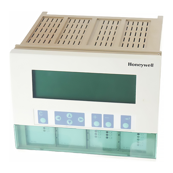
External Installation of XI582AH Operator Interface ............................................... 11
Deactivating Backlit Display of the XI582AH........................................................... 12
Distributed I/O Installation ....................................................................................... 13
Dimensions ............................................................................................................. 14
Excel 500/600..................................................................................................... 14
Excel 500-XCL5010............................................................................................ 15
XI582AH ............................................................................................................. 16
Battery Activation during Commissioning (XC6010, only) ....................................... 17
Replacing the Battery.............................................................................................. 17
Dismantling the Control Panel Unit ......................................................................... 18
Dismantling the Control Panel Door Unit................................................................. 18
Dismantling the Housing Cover............................................................................... 18
Dismantling the Excel 500-XCL5010 Control Panel Unit......................................... 18
Dismantling the XI582AH Operator Interface .......................................................... 19
Cable Routing ......................................................................................................... 20
Shielding Input / Output Module and Power Supply Cables.................................... 20
Shielding of Data-Transmitting Cables.................................................................... 20
Grounding (XC5010C / XC6010, only) .................................................................... 20
System Ground ....................................................................................................... 20
RFI Suppression ..................................................................................................... 20
XC5010C / XC6010 Cable Lengths and Sizes........................................................ 21
Lightning Protection ................................................................................................ 21
Summary of Internal Modules ................................................................................. 22
Excel 500/600
CONTROL SYSTEM
INSTALLATION INSTRUCTIONS
CONTENTS
EN1R-1047GE51 R0902 / 95-7524-3
Advertisement
Table of Contents

Related Manuals for Honeywell Excel 500


Summary of Contents for Honeywell Excel 500
-
Page 1: Table Of Contents
Safety Instructions ..................................5 MOUNTING ....................................6 Control Unit Installation ..................... 6 Excel 500/600 Housing Layout (not XCL5010) ............6 Excel 500/600 Internal Bus Wiring (not XCL5010)............ 6 Module Locations (not XCL5010)................7 Coding the Terminal Block (not XCL5010)..............7 Setting the Module Address (not XCL5010).............. - Page 2 System Bus Cable Specification................. 37 C-Bus Extension by Using Repeaters ..............38 C-Bus Termination (Excel 600) ................38 C-Bus Termination (Excel 500) ................38 C-Bus Termination (Excel 500-XCL5010) ............38 Excel 600 Cable Specifications................39 Excel 500 Cable Specifications................40 Excel 500-XCL5010 Cable Specifications ..............
-
Page 3: Excel
EXCEL 500/600 INSTALLATION INSTRUCTIONS GSM Antenna Installation ..................47 M20 Terminal Set-up....................47 Trademark Information Echelon, LON, L , LonBuilder, NodeBuilder, LonManager, ORKS LonTalk, LonUsers, LonPoint, Neuron, 3120, 3150, the Echelon logo, the L logo, and the LonUsers logo are trademarks of Echelon Corporation registered in the United States and other countries. -
Page 4: Revision Overview
EXCEL 500/600 INSTALLATION INSTRUCTIONS REVISION OVERVIEW On the following pages, changes have been made compared to the previous release of this document: Page: Change: throughout Information regarding Distributed I/O modules has been removed. Please refer instead to Distributed I/O Product Data (EN0B-0090GE51). -
Page 5: Safety Instructions
Installation Instructions are to be observed. CAUTION — The Excel 500/600 controller may be installed and Disconnect the power supply before you start to install mounted only by authorized and trained personnel. the Excel 500/600 Controller. Do not reconnect the power supply until you have completed installation. -
Page 6: Mounting
1.5 in. (35 mm) should be taken into consideration to enable the hinged cover to be opened. The maximum The Excel 500-XCL5010 can be mounted only on a DIN rail; spacing between housings is limited by tailor-made internal control panel door installation is not possible. -
Page 7: Module Locations (Not Xcl5010)
EXCEL 500/600 INSTALLATION INSTRUCTIONS — Type XW569 13 in. (330 mm) long (for housings one Table 1. Internal module locations above the other) Module Type Module location XC5010C / CAUTION housing, location 4 XC6010 Power Incorrectly inserted bus cables can destroy the... -
Page 8: Setting The Module Address (Not Xcl5010)
EXCEL 500/600 INSTALLATION INSTRUCTIONS CAUTION Setting the Module Address (not XCL5010) Unplugging a module before switching OFF the power In the case of application prior to CARE 4.0, you can set the supply could destroy the module. Do not unplug module address using the rotary HEX switches located on the modules with the power still connected. - Page 9 4. Make sure that the locking screws are positioned as shown in Fig. 13. 5. Plug in the enclosure. Fig. 15. Excel 500/600 extended wiring base Fig. 13. Housing locking screws and latches Using the extended wiring base the I/O terminals are accessible at run-time.
-
Page 10: Excel 500-Xcl5010
1, Prepare the door in accordance with the following. dimensions. Fig. 18. Panel door mounting dimensions Fig. 16. Mounting Excel 500-XCL5010 on DIN rail 2. Insert the housing. Excel 500-XCL5010 Communication Module CAUTION Always plug in the communication module before connecting the power supply. -
Page 11: External Installation Of Xi582Ah Operator Interface
EXCEL 500/600 INSTALLATION INSTRUCTIONS External Installation of XI582AH Operator Interface 1. Remove the cover. Fig. 23. Loosening the cover Fig. 20. Housing retaining clamp 4. Turn retaining clamp to fix housing. 5. Code the terminal block (see page 7). 6. Install the base. -
Page 12: Deactivating Backlit Display Of The Xi582Ah
EXCEL 500/600 INSTALLATION INSTRUCTIONS Fig. 26. Routing the cable Fig. 29. Making electrical connections 4. If mounting on a wall, remove feet. 8. Reattach the cover. Fig. 27. Removing feet Fig. 30. Reattaching cover 5. Attach the housing to the wall. -
Page 13: Distributed I/O Installation
EXCEL 500/600 INSTALLATION INSTRUCTIONS Fig. 32. Backlight OFF jumper position When the jumper is disabled (OFF-position), the backlight is permanently deactivated. The contrast of the display can be adjusted using the potentiometer at the rear of the unit. Fig. 31. Jumper location (backlight ON position) The figure above shows the location of the jumper. -
Page 14: Dimensions
EXCEL 500/600 INSTALLATION INSTRUCTIONS Dimensions Excel 500/600 Fig. 34. Excel 500/600 outside dimensions EN1R-1047GE51 R0902... -
Page 15: Excel 500-Xcl5010
EXCEL 500/600 INSTALLATION INSTRUCTIONS Excel 500-XCL5010 Fig. 35. Excel 500-XCL5010 dimensions EN1R-1047GE51 R0902... -
Page 16: Xi582Ah
EXCEL 500/600 INSTALLATION INSTRUCTIONS XI582AH Fig. 36. XI582AH dimensions EN1R-1047GE51 R0902... -
Page 17: Battery Activation During Commissioning (Xc6010, Only)
EXCEL 500/600 INSTALLATION INSTRUCTIONS Battery Activation during Commissioning (XC6010, only) The controller is delivered from the factory with the battery in the computer module electrically isolated from the internal circuitry by a safety tag to prevent the battery from discharging in transit. -
Page 18: Dismantling The Control Panel Unit
Fig. 40. Fig. 41. Housing cover retaining clamp 2. Pull off the cover. Dismantling the Excel 500-XCL5010 Control Panel Unit Before dismantling the system, disconnect the power supply Fig. 40. Releasing housing locking screws (e.g. -
Page 19: Dismantling The Xi582Ah Operator Interface
Use a pencil or similar object to open the XI582AH Operator Interface. Fig. 43. Opening the XI582AH Operator Interface unit Fig. 42. Removing Excel 500-XCL5010 from DIN rail 1. Dismantle the controller housing as depicted. 2. Pull the lower part of the housing off the control panel. -
Page 20: Electrical Connections
(if required) is available via the All low-voltage signal and output cables should be regarded Honeywell Technical Assistance Center (TAC) or, for as communication circuits in accordance with VDE 0100 and Honeywell employees, on the Docu Server under: VDE 0800 (or NEC or other equivalent), and should therefore http://web.ge51.honeywell.de/dep/mc/TAC_Tips. -
Page 21: Xc5010C / Xc6010 Cable Lengths And Sizes
Lightning Protection Type of signal ≤ ≤ ≤ ≤ 300 ft ≤ ≤ ≤ ≤ 550 ft ≤ ≤ ≤ ≤ 1300 ft Please contact your local Honeywell representative for (100 m) (170 m) (400 m) information on lightning protection. -
Page 22: Summary Of Internal Modules
EXCEL 500/600 INSTALLATION INSTRUCTIONS Summary of Internal Modules Table 4. Summary of Excel 500/600 internal modules Module Name Inputs Outputs Manual override switches LED display Service LED ORKS C-Bus transmit C-Bus receive Reset button XC5010C, Normal Computer module service button... -
Page 23: Line Power Supply
-002 120 Vac from separate transformer A separate CRT 6 or 1450 series (U.S.) transformer must be used for each of the EXCEL 500/600 controller's 24 V supply. 24 Vac, 100 VA, and 24 Vdc; -003 120 Vac 600 mA... -
Page 24: Xc5010C Computer Module
XD505A or XD508 can be used for local bus communication, XDM506 is used for modem communication. A stand-alone controller can be operated without a submodule. Fig. 51. Excel 500 CPU module pin-out The system bus is connected to terminal 16 (C+) and terminal 17 (C-). The field bus (L... -
Page 25: Xp502 Power Supply Module
RAM and flash EPROMs. For infor mation on C-Bus baud rates and the bus termination switch, see section "C-Bus Termination (Excel 500)" on page 38. Fig. 53. XP502 Power supply module and watchdog circuit To monitor the line power supply, the watchdog alarm must be provided with its own power or battery supply. -
Page 26: Xp502 With External Ups Xapu 24-2F (Distributed I/O Modules, Only)
XC5010C CPU module and the GND of Distributed I/O modules. The wiring diagram below is for Excel 500 installations using only Distributed I/O modules. No internal I/O modules may be Relay K1 insures that the supply of the Distributed I/O used. -
Page 27: Xp502 With External Ups Xapu 24-2F (Distributed I/O And Internal Modules)
EXCEL 500/600 INSTALLATION INSTRUCTIONS XP502 with External UPS XAPU 24-2F (Distributed XF521A Analog Input Module I/O and Internal Modules) Technical Specifications As shown in the figure below, two XAPU 24-2F UPSs are Number: required when the controller has both internal and Distributed eight inputs (AI1 –... -
Page 28: Xf526 Analog Input Module
EXCEL 500/600 INSTALLATION INSTRUCTIONS XF526 Analog Input Module Fig. 58 shows several connection examples for various sensors: WS21 Wind Sensor; SAF 25 Solar Sensor; and VMP Technical Specifications Feedback Potentiometer. Number: eight inputs (AI1 – AI8) Input: 0...10 Vdc (low-input impedance, 25kOhm to 10 V / 200kOhm to GND);... -
Page 29: Xf523A Digital Input Module
(default), the LED will illuminate when energized (normally open contacts). In the OFF position, the LED will illuminate when de-energized (normally closed contacts). Max. signal voltage from non-Honeywell voltage sources: Fig. 60. XF526 Analog Input module connections DC Voltage: V... -
Page 30: Xf522A And Xf527 Analog Output Modules
EXCEL 500/600 INSTALLATION INSTRUCTIONS XF522A and XF527 Analog Output Modules XF524A and XF529 Digital Output Modules Technical Specifications Technical Specifications Number: Number: 8 analog outputs 6 digital outputs Voltage rating: Voltage rating: 0 to 10 V, max. 11V 240 Vac max. per contact and per module... -
Page 31: Xf525A Three-Position Output Module
EXCEL 500/600 INSTALLATION INSTRUCTIONS XF525A Three-Position Output Module An L 16 miniature circuit breaker or G 10 A quick blow fuse should be used to protect the 240 Vac mains supply. Technical Specifications Voltage rating: NOTE: The maximum voltage for the U.S. is 24 V. -
Page 32: Excel 500-Xcl5010
For direct communication the external operator interface XI582 and the PC-based MMI XI584 can be connected to the serial port. Power Supply The Excel 500-XCL5010 controller is powered by an external Fig. 66. Excel 500-XCL5010 terminal block location transformer. Serial Port... -
Page 33: Screw Terminal Block Installation Procedure
EXCEL 500/600 INSTALLATION INSTRUCTIONS Table 13. 1450 Series transformers Part # Primary side Secondary side 1450 7287 -001 120 Vac 24 Vac, 50 VA 2 x 24 Vac, 40 VA and 100 VA -002 120 Vac from separate transformer Fig. 69. Transformer example... -
Page 34: Pull-Up Resistor Handling (O.s. 2.04.00 Or Higher, Except For Xfl521A)
5. Make sure that the communication module is attached to the controller housing. IMPORTANT The transformer feeding the Excel 500 Controller must be in the same cabinet. For the selection of the transformer, the max. DC current must be considered if field devices with DC load are used. - Page 35 EXCEL 500/600 INSTALLATION INSTRUCTIONS 10 Vdc Immersion temperature sensor VF 100 Air duct temperature sensor LF 100 25K ohm Wind sensor: Wind sensor WS21. Further connections: Temperature sensor terminal TF26 200K ohm Table 15. Accuracy of analog input sensors ground Fig.
-
Page 36: Communications
JY (St) Y 2x2x0.8 cable increases the maximum problems, particularly when adding on to an existing bus. length 3000 ft (900 m) for each repeater. On the Excel 500-XCL5010 controller, the L ORKS connections are located on the communication module as Table 16. -
Page 37: System Bus (C-Bus)
OFF. Up to 30 controllers can communicate with one another and a PC central via the system bus. Instead of an Excel 500/600 The maximum communication speed of the XC5010C / controller, other system bus compatible components can also XCL5010 is 76800 baud. -
Page 38: C-Bus Extension By Using Repeaters
EXCEL 500/600 INSTALLATION INSTRUCTIONS Inside the cabinet: The XD508 submodule is equipped with a DIP switch which activates (ON position) deactivates (OFF position) a J-Y-(ST)Y 2 x 2 x 0.8 terminating resistor. Depending on where the controller is Outside the cabinet: located on the bus the DIP switch settings must be as follows: A-Y-(ST) 2 x 2 x 0.8... -
Page 39: Excel 600 Cable Specifications
For connection to the XI584 Operator and Service Computer, a tailor-made cable is available with plugs on both ends. — XW567 cable, length 7 ft (2.5m) Fig. 84. Excel 500-XCL5010 C-Bus DIP switch location Table 23. DIP switch settings for C-Bus termination (Excel 500-XCL5010) -
Page 40: Excel 500 Cable Specifications
— XW582 cable, front connection, length 15 ft (5 m) — XW583 cable, back connection, length 15 ft (5 m) Fig. 88. Excel 500 / XI584 operator and service computer cable details NOTE: You can also use a standard null modem cable. -
Page 41: Excel 500-Xcl5010 Cable Specifications
MMIs. Excel 500-XCL5010 Controller. The serial port of the Excel 500-XCL5010 controller accepts a Table 24. Cable specifications standard modem cable with a female 9-pin connector. Use the cable that is supplied with the modem/ISDN terminal... - Page 42 EXCEL 500/600 INSTALLATION INSTRUCTIONS Fig. 90. Excel 500 and Excel 600 used together with XI584 and XI582 Operator Interfaces Fig. 91. XW584 cable details EN1R-1047GE51 RR0902...
-
Page 43: Remote Communications
The front serial port of the XC5010C CPU accepts a standard modem cable with a female 9-pin connector. Fig. 93. Serial port location on Excel 500-XCL5010 Use the cable that is supplied with the modem/ISDN terminal adapter. The communication speed is 9600 baud by default but can be set as high as 38.4 Kbaud. -
Page 44: Automatic Baudrate Synchronization
XBS system configuration/site definition screen factory default settings. prior to sending the set-up to the remote Excel 500 The communication speed between the XBS and its controller. modem/ISDN terminal adapter is part of the modem set-up at the XBS. -
Page 45: M20T Safety Precautions
EXCEL 500/600 INSTALLATION INSTRUCTIONS modem connected to the Excel controller serial port, and it address all questions to a doctor or the then transmits via GSM like a cellular (mobile) phone. manufacturer of the medical device. NOTE: Communication via GSM requires firmware version V2.3.0 or higher. -
Page 46: Serial Cable
• Safety: EN 60950 • GSM network: TBR 19, TBR 20 Serial Cable For connecting the M20T to the Excel 500 controller, a standard RS232 cable (9-pin V24 sub-D sockets) is required. GSM Antenna Requirements All major suppliers of GSM antennas can supply GSM900 Antennas with FME plugs to connect with the M20 Terminal Fig. - Page 47 EXCEL 500/600 INSTALLATION INSTRUCTIONS GSM Antenna Installation M20 Terminal Set-up The maximum antenna cable length is 8.0m (including the 20 Prior to beginning the set-up, get the M20T manual (or CD- cm M20 Terminal cable). Use a cable that is specified by the ROM, if it was delivered with one).
- Page 48 EXCEL 500/600 INSTALLATION INSTRUCTIONS NOTE: As soon as the PIN is entered into the Excel controller, the following mechanisms will take place automatically: — Cyclical check (once per minute) for existence of the PIN number in the M20 (AT+CPIN?) —...