Advertisement
Solid State Economizer System
(CONSISTING OF: C7046C DISCHARGE AIR SENSOR OR C7150B MIXED AIR SENSOR, C7400 SOLID STATE ENTHALPY
SENSOR OR C7660 SOLID STATE TEMPERATURE SENSOR, M7415, M7215 OR M8405 DAMPER ACTUATORS OR MODU-
LATING DIRECT COUPLED ACTUATORS (MS7503 or MS7505) T6031H THERMOSTAT AND W7459 OR W7212 SOLID
STATE ECONOMIZER LOGIC MODULE)
C7046C
C7150B
W7459A,C
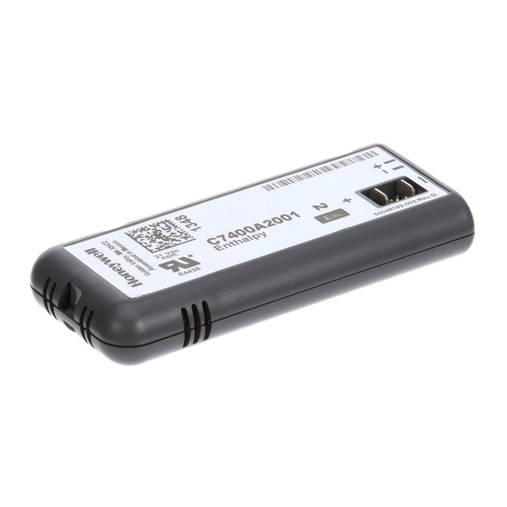
C7400A/C7660
APPLICATION
The Solid State Economizer System provides an economical
method of providing cooling air by incorporating outdoor air in
the first stage of cooling in heating, ventilating and air
conditioning (HVAC) systems. The Solid State Economizer
System consists of the C7046C Discharge Air Sensor or
C7150B Mixed Air Sensor, C7400 Solid State Enthalpy
Sensor or C7660 Solid State Temperature Sensor, M7215,
M7415 or M8405 Damper Actuators or Modulating Direct
Coupled Actuators (MS7503 or MS7505), T6031H Thermostat
and W7212A,C or W7459A,C Solid State Economizer Logic
Module.
M7215/M7415/
M8405
W7212A,C
T6031H
SYSTEM ENGINEERING GUIDE
FEATURES
C7046C Discharge Air Sensors have probe lengths of 8 in.
(203 mm) and nominal sensor resistance of 3000 ohms at
77°F (25°C).
• No setting or calibration required.
• Solid state components not affected by dust or dirt.
• Fast reacting.
• Rugged aluminum insertion probe.
C7150B Mixed Air Sensor is used with the W7212/W7459
Economizer Module to sense mixed or discharged air in roof-
top packaged air conditioning equipment.
• No setting or calibration required.
C7400 Solid State Enthalpy Sensor and C7660 Solid State
Temperature Sensors are used with the W7212/W7459 Solid
State Economizer Logic Module to sense outdoor and return
air enthalpy or temperature.
• C7400 senses and combines temperature and humidity
(enthalpy) of outdoor air (heat index).
• C7660 senses temperature only and can only be used
in single referential control. Use C7400 enthalpy for
differential control.
• When enthalpy/temperature of outdoor air increases,
the outdoor air damper closes to a preset minimum
position.
• When enthalpy/temperature of outdoor air is low, the
outdoor air damper opens to reduce the building
cooling load.
63-2484—03
Advertisement
Table of Contents

Related Manuals for Honeywell C7400


Summary of Contents for Honeywell C7400
- Page 1 Solid State Economizer System (CONSISTING OF: C7046C DISCHARGE AIR SENSOR OR C7150B MIXED AIR SENSOR, C7400 SOLID STATE ENTHALPY SENSOR OR C7660 SOLID STATE TEMPERATURE SENSOR, M7415, M7215 OR M8405 DAMPER ACTUATORS OR MODU- LATING DIRECT COUPLED ACTUATORS (MS7503 or MS7505) T6031H THERMOSTAT AND W7459 OR W7212 SOLID...
- Page 2 Unoccupied operation. T6031H Thermostat acts as changeover thermostat. • Maximum economizer savings is achieved with two (2) C7400 enthalpy sensors, one (1) W7212 economizer • Switches enclosed to resist effects of dust and logic module, and one (1) C7232 CO sensor using moisture.
-
Page 3: Specifications
Sensitivity: 70 ohms per degree F (124 ohms per degree C) at midrange. Output Signal: C7400: 4 to 20 mA current signal; increases from 4 mA to Mounting Arrangement: 20 mA as enthalpy decreases. Integral mounting flange that requires two no. 8 screws C7660: 4 or 20 mA signal;... - Page 4 7/32 (14) large loads such as a seized damper. 1 (25) M9096 Stroke: Fig. 3. Approximate dimensions of C7400 Solid State Travel: 90°. Enthalpy Sensor/C7660 Solid State Temperature Sensor Timing: in in. (mm). Driving: 86 ±5 seconds. Spring Return: 13 ±5 seconds.
- Page 5 SOLID STATE ECONOMIZER SYSTEM Terminal Connections: 1/4 in. (6 mm) quick-connect Approvals: terminals mounted on motor. Underwriters Laboratory Inc.: Flammability Rating: UL94-5V. Component Recognized: File No. E4436, Guide No. Shaft: Single-ended drive shaft with crank arm supplied. XAPX2, Vol. 9, Section 1, 7-25-83. Reliability: Full-Stroke Cycles: 60,000.
- Page 6 LOGIC MODULE See Table 3. Dimensions: Models: W7212A, W7213A, W7214A Logic Modules: for use See Fig. 6. with any Honeywell 2-10 Vdc actuator; includes DCV input; adjustable exhaust fan setpoint. NOTES: — All models include a minimum damper position potentiometer, and setpoints for: occupied/unoc- cupied control, DCV operation, and DCV maxi- mum.
- Page 7 SOLID STATE ECONOMIZER SYSTEM Dimensions: See Fig. 7. C7150B Mixed Air Temperature Sensor. C7232A,B Carbon Dioxide Sensors. Electrical Ratings: C7632 Carbon Dioxide Sensor. Input Voltage: 24 Vac ±20%; 50/60 Hz (Class 2). Nominal C7400A Solid State Enthalpy Sensor used with W7212A, Power Consumption (at 24 Vac, 60 Hz): 11.5 VA.
-
Page 8: Location And Mounting
SOLID STATE ECONOMIZER SYSTEM INSTALLATION: M7215, M7415, M8405 When Installing this Product... 1. Read instructions carefully. Failure to follow them could damage the product or cause a hazardous condition. MAXIMUM MAXIMUM 2. Check ratings and description given in the specifications OPEN CLOSED POSITION... - Page 9 SOLID STATE ECONOMIZER SYSTEM 1. Cut a 1/2 in. (13 mm) hole in the duct or plenum surface SYSTEM DUCT OR PLENUM at the desired location. 2. Insert the sensor probe into the duct or plenum hole until the flange rests against the duct or plenum wall. 3.
- Page 10 SOLID STATE ECONOMIZER SYSTEM IMPORTANT Frequency 50/60 Hz Failure to follow these wiring practices can introduce Spring Return Direction By orientation. Actuator can be electrical interference (noise) that can cause erratic flipped. system operation: Rotational Stroke 95 ±3 degrees Rotational Stroke Adjustment Mechanically limited 5 a.
- Page 11 SOLID STATE ECONOMIZER SYSTEM Disconnect the power supply before connecting wiring to CAUTION prevent electrical shock and equipment damage. All wiring must comply with applicable local codes and ordinances. Equipment Damage Hazard. Mounting screws longer than 5/8 in. can damage Refer to Fig.
-
Page 12: Operation And Checkout
Outdoor air sensing: Mount the C7400 Enthalpy Sensor or C7660 Temperature Sensor in any orientation where it is The C7400 Solid State Enthalpy Sensor is used with a solid exposed to freely circulating air but protected from rain, snow state economizer control and damper actuator to proportion and direct sunlight. - Page 13 SOLID STATE ECONOMIZER SYSTEM C7660 Solid State Temperature Sensor When outdoor air temperature is higher than changeover set point, the outdoor air damper closes to the minimum position. The C7660 Solid State Temperature Sensor is used with a When the outdoor air temperature is below the changeover solid state economizer control and damper actuator to set point, the outdoor air damper proportions open on a call proportion an outdoor air damper in a ventilation system.
- Page 14 SOLID STATE ECONOMIZER SYSTEM (29) (32) (35) (38) (41) (43) CONTROL CONTROL POINT CURVE APPROX. °F (°C) AT 50% RH (27) 73 (23) 70 (21) 67 (19) 63 (17) 55 (13) (24) (21) (18) (16) (13) (10) (10) (13) (16) (18) (21) (24)
- Page 15 SOLID STATE ECONOMIZER SYSTEM c. Mid-position—when the controller circuit closes to C7400C SENSOR OUTPUT CURRENT provide 24 Vac to terminals T and X, the actuator is energized to run to the adjustable mid-position (min- imum position). Adjustable minimum position can be reached from either the fully closed or fully open position.
-
Page 16: Settings And Adjustments
SOLID STATE ECONOMIZER SYSTEM W7213 (CHANGEOVER TERMINAL B) Connect the B terminal according to the following details: — 24V power to B: System is in heating mode. — No power to B: System is in cooling mode. C7150 W7214 (CHANGEOVER TERMINAL O) Connect the O terminal according to the following details: M7415 —... -
Page 17: Sequence Of Operation
AIR IS SUITABLE a. On the standard (non-differential) economizers, the FOR FREE COOLING logic module checks the outdoor air C7400 Enthalpy Sensor or C7660 Temperature Sensor to determine if the enthalpy or temperature is below the setpoint. b. On the differential economizers, the logic module... - Page 18 Changeover Sensor(s) or C7660 Dry Bulb Temperature cooling, whenever possible, to reduce compressor operation. Sensor. The C7400 responds to both dry bulb temperature and humidity, allowing use of outdoor air at higher Power at the N terminal determines the Occupied/Unoccupied temperatures for free cooling when humidity is low.
- Page 19 SOLID STATE ECONOMIZER SYSTEM Table 5. W7212 Economizer I/O Logic. INPUTS OUTPUTS Enthalpy Compressor N Terminal Occupied Unoccupied Demand Control Ventilation (DCV) Outdoor Return Stage 1 Stage 2 Damper Below set (DCV High (Free Minimum position Closed LED Off) Cooling LED Off) Low (Free High Modulating...
-
Page 20: Minimum Position Adjustment
SOLID STATE ECONOMIZER SYSTEM Minimum Position Adjustment For detailed assistance in minimum position selection EXHAUST FAN SETPOINT reference the Economizer Application Guide (form 63-8594) Ventilation section. The following provides basic guidelines for LED LIGHTS WHEN EXHAUST minimum position selection and adjustment: CONTACT IS MADE MINIMUM DAMPER IMPORTANT... -
Page 21: Checkout And Troubleshooting
620 OHM MILLIAMMETER JUMPER Differential Enthalpy Changeover Setting Differential enthalpy control uses two C7400 Enthalpy Sensors connected to one logic module. The logic module compares outdoor air to return air. LED LIGHTS WHEN OUTDOOR AIR IS SUITABLE... - Page 22 ENSURE THAT EQUIPMENT TRANSFORMER IS SIZED TO HANDLE THE EXTRA LOAD OF THE ECONOMIZER AND ACTUATOR. RELAYS 1K AND 2K ACTUATE WHEN THE ENTHALPY SENSED BY THE C7400 IS HIGHER THAN THE ENTHALPY SETPOINT A-D. FACTORY INSTALLED 620 OHM, 1 WATT, 5% RESISTOR SHOULD BE REMOVED ONLY IF A C7400 ENTHALPY SENSOR IS ADDED TO S R AND + FOR DIFFERENTIAL ENTHALPY.
- Page 23 1S IS AN ELECTRONIC SWITCH THAT CLOSES WHEN POWERED BY A 24 VAC INPUT. RELAYS 1K AND 2K ACTUATE WHEN THE ENTHALPY SENSED BY THE C7400 IS HIGHER THAN THE ENTHALPY SETPOINT A-D. FACTORY INSTALLED 620 OHM, 1 WATT, 5% RESISTOR SHOULD BE REMOVED ONLY IF A C7400 ENTHALPY SENSOR IS ADDED TO S R AND + FOR DIFFERENTIAL ENTHALPY.
- Page 24 C7150B MIXED AIR OR C7046A – 2-10 VDC CONTROL DISCHARGE AIR SENSOR SIGNAL INPUT – 0/2-10 VDC INDOOR AIR SENSOR M7215 W7212 C7400 OUTDOOR 620 OHM ENTHALPY RESISTOR (HOT) SENSOR EXHAUST COOL 1 COOL 2 HEAT 2 HEAT 1 (HOT)
- Page 25 C7150B MIXED AIR OR C7046A – 2-10 VDC CONTROL DISCHARGE SIGNAL INPUT AIR SENSOR – 0/2-10 VDC INDOOR AIR SENSOR M7215 W7212 C7400 OUTDOOR 620 OHM ENTHALPY RESISTOR (HOT) SENSOR EXHAUST COOL 1 COOL 2 HEAT 2 HEAT 1 (HOT)
- Page 26 C7150B MIXED AIR OR C7046A – 2-10 VDC CONTROL DISCHARGE AIR SENSOR SIGNAL INPUT – 0/2-10 VDC INDOOR AIR SENSOR M7215 W7212 C7400 OUTDOOR 620 OHM ENTHALPY RESISTOR (HOT) SENSOR EXHAUST COOL 1 COOL 2 HEAT 2 HEAT 1 (HOT)
- Page 27 SEE WIRING DIAGRAMS FOR T7350 AND TB7220/TB8220. TIME CLOCK IS AN OPTION TO USING OCCUPIED CONTACTS ON THE THERMOSTAT. Fig. 34. W7212 used in single-stage cooling system with single enthalpy changeover and Honeywell actuator and time clock for occupancy. 63-2484—03...
- Page 28 FACTORY INSTALLED 620 OHM, 1 WATT, 5% RESISTOR SHOULD BE REMOVED ONLY WHEN A C7400 ENTHALPY SENSOR IS ADDED TO SR AND SR+ FOR DIFFERENTIAL ENTHALPY. M24220 Fig. 35. W7212 used in two-stage cooling system with Honeywell Series 72 Actuator and time clock for occupancy. 63-2484—03...
- Page 29 EF AND EF1 ARE DRY CONTACTS IN THE LOGIC MODULE. SEE WIRING DIAGRAMS FOR T7350 M24221 AND TB7220/TB8220. TIME CLOCK IS AN OPTION TO USING OCCUPIED CONTACTS ON THE THERMOSTAT. Fig. 36. W7212 controlling parallel-wired Honeywell Series 72 Actuators and time clock for occupancy. 63-2484—03...
- Page 30 FACTORY INSTALLED 620 OHM, 1 WATT, 5% RESISTOR SHOULD BE REMOVED ONLY WHEN A C7400 ENTHALPY SENSOR IS ADDED TO SR AND SR+ FOR DIFFERENTIAL ENTHALPY. T7300 TERMINALS A2 AND A3 ARE CONNECTED WHEN THERMOSTAT IS IN THE UNOCCUPIED MODE.
- Page 31 SOLID STATE ECONOMIZER SYSTEM Table 6. Troubleshooting modulating economizer—outdoor enthalpy above setpoint. Condition on Logic Module Should Be Condition Not Met 1. Red LED not lighted. 1. If the LED glows, the Logic Module recognizes conditions are good for free cool- ing.
- Page 32 SOLID STATE ECONOMIZER SYSTEM Table 8. Troubleshooting three-position economizer—outdoor enthalpy above setpoint. Condition on Logic Module Should Be Conditions Not Met 1. Red LED not lighted. 1. If the LED glows, the module is in the economizer mode. Verify the conditions are above the enthalpy setpoint, see Note 2.
- Page 33 CHECKOUT AND TROUBLESHOOTING. JUMPER USED FOR SINGLE ENTHALPY CONTROL. M20612 Fig. 38. Meter location for checkout and troubleshooting (W7212 shown). Table 10. Checkout for W7212, W7213, W7214 Economizers Connected to Honeywell Actuator. Step Checkout Procedure Proper Response CHECKOUT PREPARATION Disconnect power at TR and TR1.
-
Page 34: Checkout Procedure
SOLID STATE ECONOMIZER SYSTEM Table 10. Checkout for W7212, W7213, W7214 Economizers Connected to Honeywell Actuator. (Continued) Step Checkout Procedure Proper Response DCV AND EXHAUST Execute step one, Checkout Preparation. – Ensure terminals AQ and AQ1 are open. LED for both DCV and Exhaust should be off. - Page 35 SOLID STATE ECONOMIZER SYSTEM 63-2484—03...
- Page 36 SOLID STATE ECONOMIZER SYSTEM By using this Honeywell literature, you agree that Honeywell will have no liability for any damages arising out of your use or modification to, the literature. You will defend and indemnify Honeywell, its affiliates and subsidiaries, from and against any liability, cost, or damages, including attorneys’...