Table of Contents
Advertisement
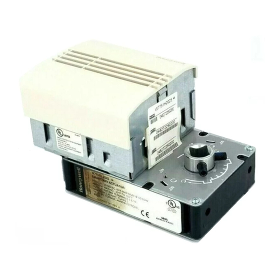
Excel 10 W7751H Smart VAV Actuator
BEFORE INSTALLATION
The W7751H Smart VAV Actuator is a factory-combined
Excel 10 Variable Air Volume (VAV) Box Controller and an
ML6174 Direct-Coupled Actuator with De-clutch mechanism.
The actuator/controller assembly is field mounted to the VAV
box damper shaft similar to the mounting of a standard
actuator, and the controller wiring is terminated to the screw
terminals that are located under a snap-on cover. See Fig. 1.
The Smart VAV Actuator is a Free Topology Transceiver (FTT)
L
M
® compliant controller. The W7751H2025 is for
ON
ARK
smoke control use.
The ML6174 Direct-Coupled Actuator with De-clutch
mechanism (see Fig. 2 for location) allows the installer to
manually open or close the VAV box damper connected to the
W7751H without power or software tool to command it.
The controller in the W7751H contains a Microbridge flow-
through pressure sensor and communicates via the
78 kilobaud Echelon® L
W
ON
Triac output loads must draw a minimum current of 25 mA at
24 Vac, 60 Hz nominal. Triac maximum current rating: 77 mA.
The actuator on the W7751H mounts directly onto the VAV
box damper shaft and has up to 70 lb-in. torque (8 Nm), 90
degree stroke, and 90 second timing at 60 Hz.
The actuator on the W7751H can accommodate the optional
field-installed auxiliary switches.
NOTE: Mounting thermostat/sensor greater than 20 ft from
the W7751H2025 requires 14506944-001 Transient
Protectors. They must be installed on the thermostat/
sensor leads from the T7770C pins 3, 4, 5, 6, and 7.
® Bus Network.
ORKS
INSTALLATION INSTRUCTIONS
INSTALLATION
Horizontally mount the W7751H on the damper shaft and
allow clearance for wiring, servicing and module removal.
Avoid mounting the W7751H in areas where acid fumes or
other deteriorating vapors can attack the metal parts of the
actuator, or in areas where escaping gas or other explosive
vapors are present. See Fig. 2 for mounting dimensions.
Fig. 1. Excel 10 Smart VAV Actuator.
IMPORTANT
The assembly is intended only for horizontal shaft
mounting, to assure proper heat dissipation from the
controller housing. The Smart VAV Actuator must not
be mounted with the controller at the top.
M19924
95-7553-04
Advertisement
Table of Contents

Related Manuals for Honeywell Excel 10 W7751H


Summary of Contents for Honeywell Excel 10 W7751H
- Page 1 Excel 10 W7751H Smart VAV Actuator INSTALLATION INSTRUCTIONS BEFORE INSTALLATION INSTALLATION The W7751H Smart VAV Actuator is a factory-combined Horizontally mount the W7751H on the damper shaft and Excel 10 Variable Air Volume (VAV) Box Controller and an allow clearance for wiring, servicing and module removal.
- Page 2 EXCEL 10 W7751H SMART VAV ACTUATOR 4-1/16 (103) 1-13/16 (46) 1-5/16 (33) 3-5/8 (92) (25) MAINTAIN A MINIMUM DISTANCE OF 3 IN. (76 MM) 1-13/16 FROM OTHER (46) DEVICES OR PANELS FOR REMOVING CONTROLLER COVER 5-7/8 (149) DE-CLUTCH LEVER 3-3/4 (95)
- Page 3 EXCEL 10 W7751H SMART VAV ACTUATOR PULL TOP OF COVER OUT, THEN DOWN, FOR REMOVAL CIRCUIT BOARD TERMINAL BLOCKS MOUNTING TAB M10000 Fig. 3. Cover removal and mounting tab/terminal block access. 3. The direction the damper shaft rotates to open the damper (CW or CCW), see Fig.
- Page 4 EXCEL 10 W7751H SMART VAV ACTUATOR degree CW slot, the damper actuator must be driven fully open (CCW). To do this, the controller on the W7751H must be wired, SHAFT ADAPTER powered, and connected to the portable PC via ®...
- Page 5 EXCEL 10 W7751H SMART VAV ACTUATOR IMPORTANT — To prevent VAV air flow connector breakage, use The minimum position set screw on the actuator is caution when removing tubing from it. Always pull not available on the W7751H device. straight away from connector; never remove by pulling at an angle.
- Page 6 EXCEL 10 W7751H SMART VAV ACTUATOR PROCEDURE 1. Determine desired switching action (i.e, if switch W7751B energizing is to occur during CW or CCW rotation). With switch cam as shown in Fig. 12, the normally closed contact opens in CCW rotation. The normally open...
- Page 7 EXCEL 10 W7751H SMART VAV ACTUATOR • Approved cable type is Level IV 22 AWG (0.34 mm plenum or non-plenum rated unshielded, twisted pair, solid conductor wire: SWITCH CAMS — For nonplenum areas, use CMP listed cable. — In plenum areas, use CMP listed cable.
- Page 8 EXCEL 10 W7751H SMART VAV ACTUATOR COMM COMM 5 4 3 2 1 5 4 3 2 1 JACK FOR JACK FOR E-BUS T7770C E-BUS T7770C NETWORK AIR FLOW NETWORK WALL ACCESS DP PICKUP ACCESS WALL MODULE MODULE AIR FLOW...
-
Page 9: Wiring Connections
), FOR EARTH GROUND WIRE. There are three methods of broadcasting the Service TO ASSURE PROPER ELECTRICAL CONTACT, WIRES MUST BE TWISTED Message from an Excel 10 W7751H Controller: TOGETHER BEFORE INSERTING INTO THE TERMINAL BLOCK. 1. Physical service pin on controller: a. - Page 10 EXCEL 10 W7751H SMART VAV ACTUATOR Alarms NOTE: During item 2, the occupancy override state of the controller changes based on how long the The commissioning tool is used to perform the ID Assignment bypass/override button is depressed. For task. Once the ID Assignment and commissioning has been example, if the button is pressed for 6 sec., the...
- Page 11 EXCEL 10 W7751H SMART VAV ACTUATOR SERIES OR PARALLEL W7751H TRIAC EQUIVALENT NOT EARTH GROUND CIRCUIT ML7984B PWM VALVE ACTUATOR CONTACTOR (24 VAC) E-BUS WALL MODULE REHEAT VALVE ACTUATOR 24 VAC MAKE SURE ALL TRANSFORMER/POWER WIRING IS AS SHOWN; REVERSING TERMINATIONS WILL RESULT IN EQUIPMENT MALFUNCTION.
- Page 12 EXCEL 10 W7751H SMART VAV ACTUATOR T7770C or D Wall Module Override LED — W7751H2025 Series 9, — W7761A2010, The remote override LED, located on either the T7770C or — Q7750, T7770D Wall Module will display the Manual Override mode of —...