Honeywell 7800 SERIES EC7895A Product Data
Relay
Hide thumbs
Also See for 7800 SERIES EC7895A:
- Installation instructions manual (12 pages) ,
- Wiring diagrams (12 pages) ,
- Manual (32 pages)
Table of Contents
Advertisement
Quick Links
GENERAL
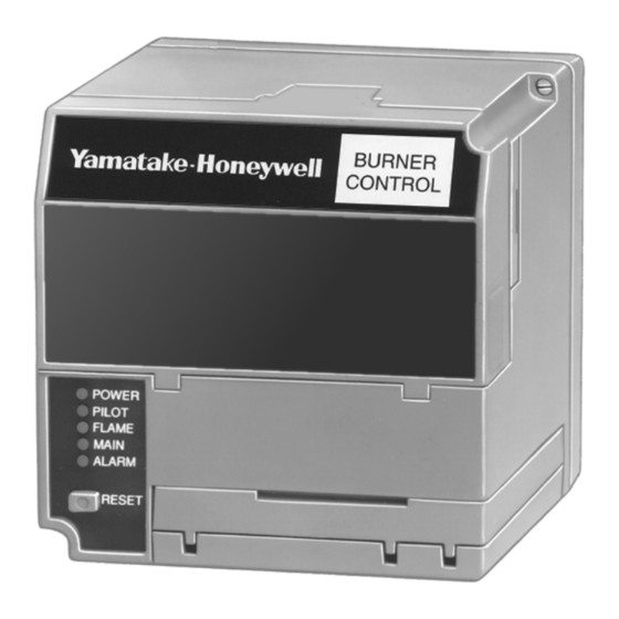
The Yamatake Honeywell EC7895A and RM7895 is a microprocessor
based integrated burner control for automatically fired gas, oil, or
combination fuel single burner applications. The RM7895 consists of
the Relay Module. Subbase, Amplifier and Purge Card. Options
include Keyboard Display Module, Personal Computer Interface,
DATA CONTROLBUS MODULE™, Remote Display Module, and
COMBUSTION SYSTEM MANAGER™ Software.
The EC7895 and RM7895 are programmed to provide a level of
safety, functional capability and features beyond the capacity of
conventional controls.
Functions provided by the EC7895 and RM7895 include automatic
burner sequencing, flame supervision, system status indication,
system or self-diagnostics and troubleshooting.
FEATURES
•
Safety features:
- Airflow switch check.
- Dynamic self-check logic.
- Internal hardware status monitoring.
•
Access for external electrical voltage checks.
•
Application flexibility.
•
Communication interface capability.
Copyright © 1996 Honeywell Inc. • All Rights Reserved
7800 SERIES EC7895A, RM7895A
Relay Module
•
Dependable, long-term operation provided by microcomputer
technology.
•
First-out annunciation and system diagnostics provided by a 2
row by 20 column Vacuum Fluorescent Display (VFD) located
on the optional Keyboard Display Module.
•
Five (LEDs) for sequence information.
•
Interchangeable plug-in flame amplifiers.
•
Local or remote annunciation of EC7895 and RM7895
operation and fault information.
•
Nonvolatile memory; EC7895 and RM7895 retain history files
and sequencing status after loss of power.
•
Remote reset (optional).
•
Report generation (optional).
•
Selectable recycle or lockout on loss of airflow.
•
Selectable recycle or lockout on loss of flame.
•
Shutter drive output.
•
Burner controller data (optional):
- Flame signal strength.
- Hold status.
- Lockout/alarm status.
- Sequence status.
- Sequence time.
- Total cycles of operation.
- Total hours of operation.
- Fault history providing for the six most recent faults:
•
Cycles of operation at the time of the fault.
•
Fault message and code.
•
Hours of operation at the time of the fault.
•
Sequence status at the time of the fault.
•
Sequence time at the time of the fault.
- Diagnostic information:
•
Device type.
•
Flame amplifier type.
•
Flame failure response time.
•
Manufacturing code.
•
On/Off status of all digital inputs and outputs.
•
Selected prepurge time.
•
Software revision and version of EC7895 and RM7895
and optional Keyboard Display Module.
•
Status of configuration jumpers.
General .........................................................................................
Features ........................................................................................
Specifications ................................................................................
Ordering Information .....................................................................
Principal Technical Features .........................................................
Safety Provisions ..........................................................................
Installation .....................................................................................
Wiring ............................................................................................ 11
Assembly ...................................................................................... 14
Operation ...................................................................................... 17
Checkout ....................................................................................... 20
Troubleshooting ............................................................................ 26
X-XX UL
PRODUCT DATA
Contents
1
1
2
2
8
8
9
65-0205
Advertisement
Table of Contents

Related Manuals for Honeywell 7800 SERIES EC7895A


Summary of Contents for Honeywell 7800 SERIES EC7895A
-
Page 1: Table Of Contents
Fault message and code. • Hours of operation at the time of the fault. The Yamatake Honeywell EC7895A and RM7895 is a microprocessor • Sequence status at the time of the fault. based integrated burner control for automatically fired gas, oil, or •... -
Page 2: Specifications
Honeywell, 1885 Douglas Drive North Minneapolis, Minnesota 55422-4386 In Canada—Honeywell Limited/Honeywell Limitée, 35 Dynamic Drive, Scarborough, Ontario M1V 4Z9. International Sales and Service Offices in all principal cities of the world. Manufacturing in Australia, Canada, Finland, France, Germany, Japan, Mexico, Netherlands, Spain, Taiwan, United Kingdom, U.S.A. - Page 3 7800 SERIES EC7895A, RM7895A RELAY MODULE Model: Electrical Ratings, see Table 1B: EC7895 Voltage and Frequency: 200 Vac (+10/-15%), 50 or 60 Hz (+/- 10%). Power Dissipation: EC7895: 10W maximum. Maximum Total Connected Load: 2000 VA. Fusing Total Connected Load: 20A maximum, type FRN or equivalent.
- Page 4 7800 SERIES EC7895A, RM7895A RELAY MODULE Environmental Ratings: Weight: Ambient Temperature: RM7895 with Dust Cover: 1 pound 15 ounces, unpacked. Operating: -40° F to 140° F. Storage: -60° F to 150° F. IMPORTANT Flame Detection System available for use with Humidity: 85% RH continuous, noncondensing.
- Page 5 7800 SERIES EC7895A, RM7895A RELAY MODULE Sequence Timing For Normal Operation: Flame Establishing Period Device Initiate Standby Purge Pilot Main EC7895A/RM7895A 10 sec. 4 or 10 sec. * STANDBY and RUN can be an infinite time period. ** PURGE is determined by the ST7800A Purge Card selected.
- Page 6 7800 SERIES EC7895A, RM7895A RELAY MODULE BURNER CONTROL (127) POWER PILOT FLAME MAIN ALARM RESET 6-3/32 (155) 5 (127) REMOVE ONLY FOR TERMINAL TEST ACCESS. M11134 Fig. 2. Mounting dimensions of EC7895/RM7895 Relay Module and Q7800B Subbase in in. (mm).
- Page 7 7800 SERIES EC7895A, RM7895A RELAY MODULE 4-1/8 (105) 2 (51) 1/2-14 NPSM COLLAR WITH 1–11-1/2 NPSM INTERNAL THREADS 1-3/16 INTERNAL (30) 4 (102) 6 FOOT (1.83 METER) THREADS LEADWIRES (2) 3-1/2 (89) 31/32 1-1/2 (25) (38) 1-1/16 (27) 6 FOOT 2-5/8 (67) [1.83 METER]...
-
Page 8: Closed Loop Logic Test
7800 SERIES EC7895A, RM7895A RELAY MODULE 11-13/16 (300) 2-5/32 1-27/32 1 INCH NPT 7-13/16 (198) 5-13/16 (147) (55) (47) 15/16 [24] DIA. 5-13/16 6-7/32 (147) (158) 2-1/2 (64) 6-19/32 (168) 1 (25) 15/16–18 UNC (2 EACH) C7076D 2 (51) M5084A Fig. -
Page 9: Dynamic Ampli-Check
7800 SERIES EC7895A, RM7895A RELAY MODULE Dynamic Ampli-Check® Verified Spark Termination Dynamic AMPLI-CHECK® circuitry tests the flame signal The ignition terminal is monitored to assure early spark amplifier during burner operation and shuts down the EC7895 termination (ten seconds ignition and pilot and ten seconds or RM7895 if the flame amplifier fails. - Page 10 7800 SERIES EC7895A, RM7895A RELAY MODULE When Installing this Product… Humidity 1. Read these instructions carefully. Failure to follow them Install the EC7895 or RM7895 where the relative humidity could damage the product or cause a hazardous never reaches the saturation point. The EC7895 or RM7895 condition.
-
Page 11: Wiring
7800 SERIES EC7895A, RM7895A RELAY MODULE (HOT) PLUG-IN PURGE CONFIGURATION TIMER CARD JUMPERS TEST FLAME SIGNAL JACK RUN/TEST SWITCH PLUG-IN MICROCOMPUTER FLAME AMPLIFIER TEST RESET PUSHBUTTON RELAY RELAY STATUS DRIVE FEEDBACK CIRCUIT AND LINE VOLTAGE INPUTS SAFETY RELAY CIRCUIT STATUS LEDs... - Page 12 7800 SERIES EC7895A, RM7895A RELAY MODULE For EC7895 or RM7895, each device has an 7. Maximum wire lengths: earth ground terminal that must be grounded to For the EC7895 or RM7895, the maximum length the metal control panel with wire as short as of leadwire to the terminal inputs is 300 feet practical.
- Page 13 7800 SERIES EC7895A, RM7895A RELAY MODULE Q7800 200 VAC ALARM (L1) BURNER MOTOR (BLOWER) BURNER CONTROLLER/LIMITS AIRFLOW INTERLOCK INTERMITTENT PILOT/IGNITION MAIN FUEL VALVE(S) IGNITION RECTIFYING FLAME ROD, RECTIFYING (HOT) PHOTOCELL, OR INFRA- RED (LEAD SULFIDE) FLAME DETECTOR MASTER SWITCH C7027A, C7035A, OR...
-
Page 14: Assembly
7800 SERIES EC7895A, RM7895A RELAY MODULE ASSEMBLY Installing Plug-In Flame Signal Amplifier 1. Disconnect the power supply before beginning installation to prevent electrical shock and equipment Mounting RM7895 damage. More than one disconnect may be involved. 2. Align the amplifier circuit board edge connector with the NOTE: For installation dimensions, see Fig. - Page 15 7800 SERIES EC7895A, RM7895A RELAY MODULE Fig. 12. Dust Cover mounting. Fig. 10. Wall or burner installation. Fig. 13. Flame signal amplifier mounting. Fig. 11. ST7800 Purge Card installation. 65-0205...
- Page 16 7800 SERIES EC7895A, RM7895A RELAY MODULE C7076A,D ULTRAVIOLET DETECTOR INFRARED (C7015) REMOTE SENSOR WHITE EARTH GROUND BROWN SHUTTER C7076A C7076D SHUTTER TERMINAL BLOCK ULTRAVIOLET (C7027/C7035/C7044) L1 (HOT) L2 (COMMON) BLUE 7800 SERIES WHITE SOLID STATE SELF-CHECKING SOLID STATE ULTRAVIOLET (C7012E,F)
-
Page 17: Operation
7800 SERIES EC7895A, RM7895A RELAY MODULE Ignition Trials OPERATION a. Pilot Flame Establishing Period (PFEP): The pilot valve and ignition transformer, terminals 8 Sequence of Operation and 10, are energized. The EC7895 or RM7895A The EC7895 or RM7895 has the following operating has an intermittent pilot valve, terminal 8. -
Page 18: General Instructions
7800 SERIES EC7895A, RM7895A RELAY MODULE 5. For each test, open the master switch and install the Equipment Recommended jumper wire(s) between the subbase wiring terminals 1. Voltmeter (1M ohm/volt minimum sensitivity) set on the listed in the Test Jumpers column of Table 4. - Page 19 7800 SERIES EC7895A, RM7895A RELAY MODULE Table 3. Site Configurable Jumper Options. SELECTABLE CONFIGURATION JUMPERS Jumper Number Description Intact Clipped Pilot Flame 10 seconds 4 seconds Establishing Period Flame Failure Recycle Lockout Action Airflow Switch Recycle Lockout (ILK) Failure M11126 Fig.
-
Page 20: Checkout
7800 SERIES EC7895A, RM7895A RELAY MODULE CHECKOUT Checkout Summary • Preliminary inspection—all installations. • Flame signal measurement—all installations. WARNING • Initial lightoff check for proved pilot—all installations using a pilot. Do not allow fuel to accumulate in the combustion • Initial lightoff check for direct spark ignition of oil—all chamber. - Page 21 7800 SERIES EC7895A, RM7895A RELAY MODULE Flame Signal Measurement (Fig. 18 and Table 5) Table 5. Flame Signal. Acceptable Flame Minimum Maximum Flame Detector Signal Amplifier Steady DC Voltage Expected DC Voltage Flame Rod Photocell R7847A,B 1.25 Vdc C7012A,C 5.0 Vdc at the Keyboard Display Module...
- Page 22 7800 SERIES EC7895A, RM7895A RELAY MODULE NOTE: Low fuel pressure limits, if used, could be open. If 9. When the MAIN IGN period is displayed by the MAIN so, bypass them with jumpers during this check. LED, make sure the automatic main fuel valve is open;...
- Page 23 7800 SERIES EC7895A, RM7895A RELAY MODULE Make burner adjustments for flame stability and Initial Lightoff Check for Direct Spark Ignition input rating. This check applies for gas and oil burners that do not use a Shut down the system by lowering the set point of pilot.
- Page 24 7800 SERIES EC7895A, RM7895A RELAY MODULE Turn the pilot back down slightly but not enough Start the burner and monitor the flame signal during the to cause the FLAME LED to go out. (Keep the warmup period. A decrease in signal strength as the pilot gas pressure just above the reading noted in refractory heats up indicates hot refractory saturation.
-
Page 25: All Installations
Automatic pilot valve(s) should be energized but 0.5 Vdc. the pilot cannot ignite. Safety shutdown occurs. NOTE: The Honeywell Q624A Solid State Spark Generator 4. Failure to ignite main. prevents detection of ignition spark when properly Open the manual pilot valve(s); leave the main applied with the C7027, C7035 or C7044 Minipeeper fuel manual shutoff valve(s) closed. -
Page 26: Troubleshooting
7800 SERIES EC7895A, RM7895A RELAY MODULE TROUBLESHOOTING Historical Information Index The EC7895 or RM7895 has nonvolatile memory that allows the Relay Module to retain Historical Information for the six EC7895 or RM7895 System Diagnostics most recent lockouts. Each of the six lockout files retains the... - Page 27 7800 SERIES EC7895A, RM7895A RELAY MODULE Table 6. Sequence And Status Hold Information. NOTE: Normal sequences are in bold type, while abnormal sequences are not in bold type. Sequence Status INITIATE The LED indicates the burner status, POWER, which is a stabilization period for the RM7895 to check for any fluctuations in AC line voltage inputs or control input on power-up or during normal operation.
- Page 28 7800 SERIES EC7895A, RM7895A RELAY MODULE Table 6. Sequence And Status Hold Information. (Continued) NOTE: Normal sequences are in bold type, while abnormal sequences are not in bold type. Sequence Status If the EC7895 or RM7895 is in a HOLD condition, the following conditions could exist:...