Advertisement
Quick Links
Download this manual
See also:
Instruction Manual
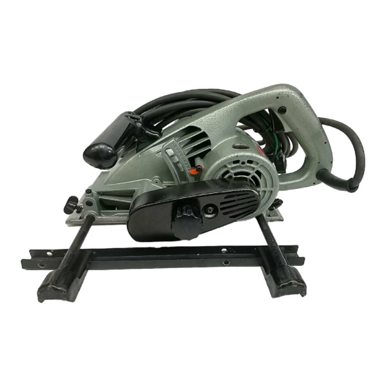
MODEL 3 8 0 3 A
Equipped with Electric Brake
Capacities
Max cutter blade size
Max. cutting depth
lf.!,~~6x i<o;y,)
31
mm
11-7/32")
INSTRUCTION MANUAL
Overall length
Net weight
No
load speed
IRPM)
9,000
41 1 mm 116-3116")
6.8
kg
(15
lbsl
Advertisement

Related Manuals for Makita 3803A


Summary of Contents for Makita 3803A
- Page 1 MODEL 3 8 0 3 A Equipped with Electric Brake INSTRUCTION MANUAL Capacities load speed Overall length Net weight IRPM) Max cutter blade size Max. cutting depth lf.!,~~6x i<o;y,) 11-7/32") 41 1 mm 116-3116") 9,000 lbsl...
-
Page 2: Important Safety Instructions
IMPORTANT SAFETY INSTRUCTIONS WARNING: When using electric tools, basic safety precautions should always be followed t o reduce the risk of fire, electric shock, and personal injury, includ- ing the following: READ ALL INSTRUCTIONS. KEEP WORK AREA CLEAN. Cluttered areas and benches invite injuries. CONSIDER WORK AREA ENVIRONMENT. - Page 3 STAY ALERT. Watch what you are doing, use common sense. Don’t operate tool w h e n you are tired. CHECK DAMAGED PARTS. Before further use of the tool, a guard or other part that is damaged should be carefully checked t o determine that will operate properly and perform i t s intended function.
- Page 4 ADDITIONAL SAFETY RULES Inspect for and remove nails or foreign matter from the workpiece before operation. Check the cutter blade carefully for cracks or damage before operation. Replace cracked or damaged cutter blade immediately. Secure the workpiece firmly. Do not wear gloves during operation. Hold the tool firmly w i t h both hands.
- Page 5 WARNING: Always be sure that the tool i s switched off and unplugged before performing any adjust- ments or installing accessories. Adjusting depth of cut Loosen the knob on the belt cover. Move the handle up down until the indication plate indicates the graduation the depth cut desired.
- Page 6 Switch action Lock button To start the tool, simply pull the trigger. Release the trigger t o stop. For continuous operation, pull the trigger and then push in the lock button. To stop the tool from the locked position, pull the trigger fully, then release it.
- Page 7 Shiplapping attachment Use the shiplapping attachment when cut- ting the edge of the workpiece. Attach the rule Guide shiplapping attachment to the guide rule using the screws. Shiplapping attachment Align the right side of the cutter blade with the cutting line. Move the guide rule until the shiplapping attachment contacts the side of the workpiece.
- Page 8 To install the cutter blade, mount the flange, cutter blade, flange and hex nut onto the spindle in that order, making sure that the cutter blade is installed with teeth pointing up a t the front of the tool. Hex nut Flange Flange WARNING:...
- Page 9 Side plates WARNING: Always make sure that the tool switched off and unplugged before installing, removing or adjusting the side plates. The side plates help to prevent splintering of workpieces. This tool is equipped with two side plate 21-30 (originally installed on the tool), a side plate 2.4- 18 (provided as a standard equipment) and a side plate 33- 46 (provided as a standard equipment).
- Page 10 When using cutter blades 110 mm (4-3/8') When using cutter blades (4-3/8") in dia. in diameter, simply re-install the indication plate upside down and adjust it so that it Indication plate points t o the " 0 ' graduation. Adjusting the scale plate WARNING: Always make sure that the tool i s switched off and unplugged before making any adjust- ment.
- Page 11 Also, the miter guide rule position can be determined using indicator on miter guide rule. Adjust the indicator so that i t s length is mm (0.02”) shorter ? < : than the distance (A) between the edge of the tool base and the side of the cutter this blade.
-
Page 12: Maintenance
Take out the worn carbon brushes, insert the new ones and secure the brush holder caps. To maintain product SAFETY and RELIABILITY, repairs, any other maintenance or adjustment should be performed by Makita Authorized or Factory Service Centers, always using Makita replacement parts. - Page 13 ACCESS0 R I ES CAUTION These accessories or attachments are recommended for use with your Makita tool specified in this manual. The use of any other accessories or attachments might present risk injury to persons. The accessories or attachments should used only in the proper and intended manner.
- Page 14 Flange 35 .Wrench Part 224051-1 #19 Part 781206-6 [For cutter blade width 2.4 (3/32") #21 Part 781208-2 (5/16")1 Wooden carrying case Screwdriver Part No. 822175-0 Part 783002-8...
- Page 15 -18-'93 GROOVE CUTTER Model 3803A Note: The switch, noise suppressor and other part configurations may differ from country to country.
- Page 16 MODEL 3803A Jan.-18-'93 'y$ $tD DESCRIPTION MACHINE MACHINE Flange V Pulley 9-49 Hex Nut M12 Pan Head Screw M4x8 (With Washer] Makita Mark Inner cover Head Screw M4x8 IWith Washer) Pan Head Screw M5x20 (With Washerl Pointer Bracket Ball Bearing 6200LLB...