Panasonic DP-100 series Instruction Manual
High-performance digital display
Hide thumbs
Also See for DP-100 series:
- Instruction manual (9 pages) ,
- Instruction manual (4 pages) ,
- Instruction manual (4 pages)
Advertisement
Quick Links
Download this manual
See also:
Instruction Manual
INSTRUCTION MANUAL
Pressure Sensor
High-performance Digital Display
DP-100
Series
Thank you very much for using SUNX products. Please read this
Instruction Manual carefully and thoroughly for the correct and optimum
use of this product. Kindly keep this manual in a convenient place for quick
reference.
Never use this product as a sensing device for personnel protection.
In case of using sensing devices for personnel protection, use products
which meet laws and standards, such as OSHA, ANSI or IEC etc., for
personnel protection applicable in each region or country.
Japanese Measurement Laws prohibit the use of this product in Japan.
1
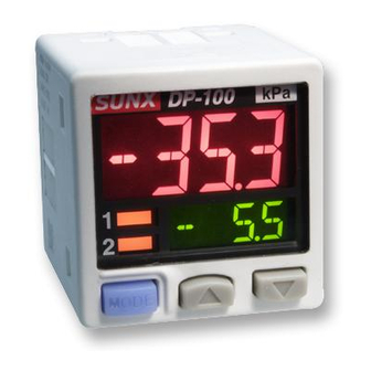
NAMES OF EACH PART
Output 1 operation
indicator
DP-100
Lights up when compa-
rative output 1 is ON
Output 2 / analog
voltage output oper-
ation indicator
Standard type:
Lights up when compa-
Setting value UP key
rative output 2 is ON
Mode selection key
High-function type:
Lights up when analog
voltage output is set
2
PIPING
When connecting a commercial coupler to the pressure port, attach a
12mm spanner (14mm for DP-100-E type) to the pressure port's hexa-
gon section to fix the port, and then tighten with a tightening torque of
9.8N m or less. The commercial coupler or pressure port section will be
damaged if the tightening torque is excessive.
Wrap sealing tape around the coupler when connecting to prevent leaks.
3
MOUNTING
The sensor mounting bracket (MS-DP1-1) is available as an option.
When mounting the sensor onto the sensor mounting bracket, etc., the
tightening torque should be 0.5N m or less.
M3 (length 6mm) screws
with washers
Sensor mounting bracket
MS-DP1-1 (Optional)
The panel mounting bracket MS-DP1-2 (optional) and front cover
MS-DP1-3 (optional) are also available as options.
Front cover
MS-DP1-3 (Optional)
For use outside Japan
MJE-DP100 No.6091-01
WARNING
Main display
Sub-display
Setting value
DOWN key
Pressure port
1
DP-100 type: R
+ M5 female screw
8
1
DP-100-E type: G
+ M5 female screw
8
1
DP-100-N type: NPT
12mm spanner
(Accessory with MS-DP1-1)
M3 (length 12mm) tapping
screw
(Accessory with MS-DP1-2)
Panel cut-out size
(Unit: mm)
0
31
0.4
Panel mounting bracket
MS-DP1-2 (Optional)
4
WIRING
Connection method
Insert the cable with connector CN-14A-C
into this product's connection connector
section as shown in the right figure.
Disconnection method
Pressing the release lever of the cable
with connector, pull out the connector.
Note: Do not pull by holding the cable without pressing the release lever, as this can
cause cable break or connector break.
<Connection connector pin arrangement>
5
I/O CIRCUIT DIAGRAMS
When using the analog voltage output, take care to the input impedance of
the connected device.
Furthermore, note that if the cable is extended, the cable resistance will
cause the voltage to drop.
Connection
connector
NPN output type
Standard type
+ M5 female screw
8
High-function type
5V
PNP output type
Standard type
High-function type
0
31
0.4
Connector pin No.
Standard type: Comparative output 2
High-function type: Analog voltage output or external input
Color code of cable with connector
(Brown) +V
(Black)
Comparative output 1
100mA max.
(White) Comparative output 2
(Blue) 0V
Internal circuit
Users' circuit
Color code of cable with connector
(Brown) +V
(White)
Analog voltage output
or external input
1kΩ
(Black) Comparative output 1
100mA max.
(Blue) 0V
Internal circuit
Users' circuit
Color code of cable with connector
(Brown) +V
(Black) Comparative output 1
100mA max.
(White) Comparative output 2
(Blue) 0V
Internal circuit
Users' circuit
Color code of cable with connector
(Brown) +V
100mA max.
(Black) Comparative output 1
1kΩ
(White)
Analog voltage output
or external input
(Blue) 0V
Internal circuit
Users' circuit
Cable with connector
CN-14A-C
Release lever
<Recommended product>
Contact: SPHD-001T-P0.5
Housing: PAP-04V-S
[JST Mfg. Co., Ltd.]
Terminal name
+V
Comparative output 1
0V
Load
Load
+
12 to 24V DC
_
±10%
100mA max.
Load
+
12 to 24V DC
_
±10%
100mA max.
+
12 to 24V DC
_
±10%
Load
Load
+
12 to 24V DC
_
±10%
Load
Advertisement

Related Manuals for Panasonic DP-100 series


Summary of Contents for Panasonic DP-100 series
- Page 1 WIRING Connection method Insert the cable with connector CN-14A-C INSTRUCTION MANUAL Cable with connector into this product's connection connector CN-14A-C section as shown in the right figure. Pressure Sensor High-performance Digital Display Disconnection method DP-100 Series For use outside Japan Release lever Pressing the release lever of the cable with connector, pull out the connector.
- Page 2 OUTPUT MODE AND OUTPUT OPERATION RUN MODE The EASY mode, hysteresis mode or window comparator mode can be Setting the threshold value DP-100 selected as the output mode for comparative output 1 and comparative Refer to 'Comparative output 1/2 output output 2.
- Page 3 High-function type MENU SETTING MODE <Setting condition 7> When the mode selection key is held down for two seconds in the Comparative output 1 output mode: ' ' (EASY mode) RUN mode, the menu setting mode will open. Analog voltage output / external input selection: ' ' (Analog voltage output) The mode will change to the RUN mode when the mode selection key is held down during this setting process.
- Page 4 PRO MODE Code table When the mode selection key is held down for four seconds in the RUN mode, the PRO mode will open. Second digit Fourth digit Third First digit The mode will change to the RUN mode when the mode selection key is held High-func- Standard digit...
-
Page 5: Main Specifications
AUTO-REFERENCE FUNCTION MAIN SPECIFICATIONS (ONLY HIGH-FUNCTION TYPE) Model The auto-reference function corrects DP-10 - - - Before auto- None: Cable with connector enclosed, J: No cable with connector reference the setting value using the detected None: NPN output type, P: PNP output type pressure value during auto-reference A f t e r a u t o - reference...