Panasonic DP-100 Series Instruction Manual
Digital display pressure sensor
Hide thumbs
Also See for DP-100 Series:
- Instruction manual (5 pages) ,
- Instruction manual (9 pages) ,
- Instruction manual (4 pages)
Advertisement
Quick Links
Download this manual
See also:
Instruction Manual
High-performance Digital Display Pressure Sensor
DP-100 Series
Thank you very much for purchasing Panasonic products. Read this Instruction Manual
carefully and thoroughly for the correct and optimum use of this product. Kindly keep
this manual in a convenient place for quick reference.
Never use this product as a sensing device for personnel protection.
In case of using sensing devices for personnel protection, use products which
meet laws and standards, such as OSHA, ANSI or IEC etc., for personnel protec-
tion applicable in each region or country.
This product is designed for use with non-corrosive gas. It cannot be used for liq-
uid or corrosive gas.
A product intended for use in Japan conforms to the Japanese Measurement Act.
Do not use a product intended for use overseas in Japan.
1
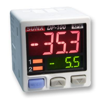
PART DESCRIPTION
Output 1 operation
indicator
Lights up when com-
parative output 1 is ON
Output 2 / analogue
voltage output opera-
tion indicator
Standard type:
Setting value UP key
Lights up when com-
parative output 2 is ON
Mode selection key
High-function type:
Lights up when analogue
voltage output is set
Notes: 1) In the case of a model that is intended for use outside Japan, attach the unit switch plate corresponds to the set
pressure unit.
2) The product for use inside Japan can be set only to "MPa" or "kPa."
2
PIPING
When connecting a commercial coupler to the pres-
sure port, attach a 12mm spanner (14mm for DP-100-E
W\SH
WR WKH SUHVVXUH SRUW¶V KH[DJRQ VHFWLRQ WR ¿[ WKH
port, and then tighten with a tightening torque of 9.8N·m
or less (M5 female: 1N·m or less). The commercial
coupler or pressure port section will be damaged if the
tightening torque is excessive.
Wrap sealing tape around the coupler when connect-
ing to prevent leaks.
3
MOUNTING
The sensor mounting bracket MS-DP1-1 is available as an option. When mounting the sen-
sor onto the sensor mounting bracket, etc., the tightening torque should be 0.5N·m or less.
M3 (length 6mm) screws
with washers
(Accessory with MS-DP1-1)
Sensor mounting bracket
MS-DP1-1 (Optional)
The panel mounting bracket MS-DP1-2 (optional) and MS-DP1-4 (optional), as well
as the front cover MS-DP1-3 (optional) and DPX-04 (optional) are also available.
The type of the front cover is different depending on the applied mounting bracket.
Use MS-DP1-3 for MS-DP1-2, and DPX-04 for MS-DP1-4.
For mounting of the panel mounting bracket, refer to the Instruction Manual en-
closed with MS-DP1-2 or MS-DP1-4.
4
WIRING
Connection method
Insert the cable with connector CN-14A-C
into this product's connection connector sec-
WLRQ DV VKRZQ LQ WKH ULJKW ¿JXUH
Disconnection method
Pressing the release lever of the cable with
connector, pull out the connector.
Note: Do not pull by holding the cable without pressing the release lever, as this can cause cable break or connector
break.
<Connection connector pin arrangement>
Connector pin No.
1
2
3
1
2
3
4
4
INSTRUCTION MANUAL
MJE-DP100 No.0025-36V
WARNING
Unit display
(Note 1, 2)
Main display
Sub display
Setting value
DOWN key
Pressure port
DP-100 type: R
1
/
+ M5 female screw
8
1
DP-100-E type: G
/
+ M5 female screw
8
DP-100-M type: M5 female screw
DP-100-N type: NPT
1
/
+ M5 female screw
8
Cable with connector
CN-14A-C
<Recommended product>
Contact: SPHD-001T-P0.5
Housing: PAP-04V-S
[JST Mfg. Co., Ltd.]
Terminal name
+V
Comparative output 1
Standard type: Comparative output 2
High-function type: Analogue voltage output or external input
0V
5
I/O CIRCUIT DIAGRAMS
When using the analogue voltage output, take care to the input impedance of the
connected device.
Furthermore, note that if the cable is extended, the cable resistance will cause the
voltage to drop.
NPN output type
Standard type
High-function type
5V
N
Connection
connector
PNP output type
Standard type
12mm spanner
High-function type
N
6
OUTPUT MODE AND OUTPUT OPERATION
The EASY mode, hysteresis mode or window comparator mode can be selected as
the output mode for comparative output 1 and comparative output 2.
Refer to <Comparative output 1 / 2 output mode setting> in "
TING MODE" for details.
EASY mode
ON / OFF of the comparative output is controlled in this mode.
Comparative
output
OFF
1RWHV
+\VWHUHVLV FDQ EH ¿[HG LQ VWHSV
Refer to +\VWHUHVLV ¿[HG YDOXH VHOHFWLRQ! in "
2) "
" is displayed for comparative output 1 and "
Hysteresis mode
The comparative output ON / OFF state can be controlled with randomly set hyster-
esis in this mode.
Release lever
Comparative
output
OFF
Note: "
" or "
sub-display.
(Brown) +V
(Black)
Comparative output 1
100mA max.
(White) Comparative output 2
(Blue) 0V
(Brown) +V
(White)
Analogue voltage output
or external input
(Black)
Comparative output 1
100mA max.
(Blue) 0V
(Brown) +V
(Black) Comparative output 1
100mA max.
(White)
Comparative output 2
(Blue) 0V
(Brown) +V
100mA max.
(Black)
Comparative output 1
(White)
Analogue voltage output
or external input
(Blue) 0V
H (Hysteresis)
P
0
ON
9
PRO MODE" for setting.
" for comparative output 2 on the sub-display.
Hi
H (Hysteresis)
Lo
0
ON
" is displayed for comparative output 1 and "
Load
Load
+
12 to 24V DC
±10%
-
100mA max.
Load
+
12 to 24V DC
±10%
-
100mA max.
+
12 to 24V DC
±10%
-
Load
Load
+
12 to 24V DC
±10%
-
Load
8
MENU SET-
+
+\VWHUHVLV ¿[HG
1RWH
H: 1digit or more
2 digits or more when
using psi unit
" or "
" for comparative output 2 on the
Advertisement

Related Manuals for Panasonic DP-100 Series


Summary of Contents for Panasonic DP-100 Series
- Page 1 MJE-DP100 No.0025-36V NPN output type Thank you very much for purchasing Panasonic products. Read this Instruction Manual Standard type carefully and thoroughly for the correct and optimum use of this product. Kindly keep this manual in a convenient place for quick reference.
- Page 2 MENU SETTING MODE Window comparator mode In this mode, the ON or OFF state of the comparative output is controlled with a The mode will change to RUN mode when the mode selection key is held down pressure in the set range. during this setting process.
- Page 3 PRO MODE Code table Main display (1st digit form left) The mode will change to RUN mode when the mode selection key is held down during this setting process. However, changed items before holding down the mode 2nd digit 4th digit 1st digit 3rd digit selection key have been set.
-
Page 4: Specifications
Phone: +81-568-33-7861 FAX: +81-568-33-8591 Europe Headquarter: Panasonic Electric Works Europe AG Rudolf-Diesel-Ring 2, D-83607 Holzkirchen, Germany Phone: +49-8024-648-0 US Headquarter: Panasonic Electric Works Corporation of America 629 Central Avenue New Providence, New Jersey 07974 USA Phone: +1-908-464-3550 PRINTED IN JAPAN...