Table of Contents
Advertisement
Save This Manual
For Future Reference
MODEL
NO.
313.228362
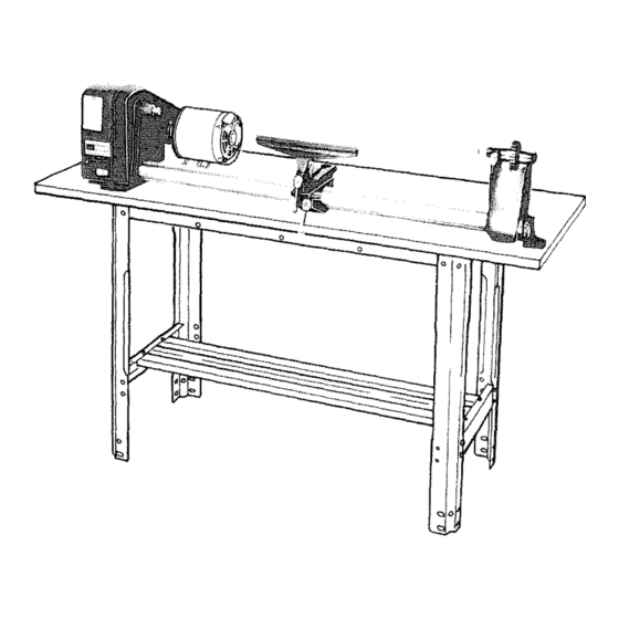
LATHE WITH MOTOR
[serial
! Number
Model and serial
number
may be found
under
belt guard.
You should
record
both
model and serial number
in a safe place for
future use.
CAUTION.
O
Read
GENERAL
and
ADDITIONAL
SAFETY
INSTRUCTIONS
cerefully
!2-INCH
WOOO-TURNING
[A THE
* assembly
, operating
®repair
parts
Sold
by
SEARS,
ROEBUCK
AND
CO.,
Chicago,
IL.
60684
U.S.A.
t No.
SP4938
_e_
,'<_
Advertisement
Table of Contents

Related Manuals for Craftsman 113.228162


Summary of Contents for Craftsman 113.228162
- Page 1 Save This Manual For Future Reference MODEL 313.228362 LATHE WITH MOTOR [serial ! Number Model and serial number may be found under belt guard. !2-INCH You should record both model and serial number WOOO-TURNING [A THE in a safe place for future use.
- Page 2 " FULL ONE YEAR WARRANTY ON CRAFTSMAN WOOD LATHE if within One year from the date of purchsse, this Craftsman Wood L_the fails due to a defect in material or workmanship. Sears will repair it, free of cha rge. WARRANTY...
- Page 3 Never operate Lathe with protective cover Safety is a combination of operator common sense and the unused shaft end of the motor removed, alertness at all times when the Lathe is being used. WARNING: YOUR OWN SAFETY, Hang your turning tools on the wall toward...
-
Page 4: Motor Specifications
WARNING: DO NOT ALLOW FAMaUARITY (GAINED WARNING: THE FOUR STEP LATHE AND MOTOR FROM FREO_ENT USE OF YOUR MACHINE) TO BE- PULLEYS FURNISHED ARE DESIGNED TO RUN THE COME COMMONPLACE. ALWAYS REMEMBER THAT LATHEATTHECORRECTSPEEDSWHENUSEDWnTH ACARELESSFRACTIONOFASECOND ISSUFFICIENT A 1725 R.PoM. MOTOR. DO NOT USE A 3450 R.P.M. - Page 5 permanent ground suchasto a property g rounded outlet mine the minimum wire size (A,W.G.} extension cord, box. only 3 wire extension cords which have 3-prong grounding Atemporary adapter type plugs and 3-pole receptacles which accept the tools as illustrated is available for connecting plug, plugs to 2 -pro ng receptecles, The temporary adapter shou Id Extension...
- Page 6 assembly 1. UnpaCk all the part_ of your wood lathe and lay them 6. Set large tool rest in tool rest holder and install locking handle as shown. 0ut in your work area so they can be recognized easily. Checkall partswith the parts table and be careful not to...
- Page 7 6 1t8' ----+--, 3'_ MOUNTING YOUR LATHE AND MOTOR A WORKBENCH HOLES FOR MOTOR 4f7/8 '" SPECIAL NOTE: For best results when mounting your lathe and motor to a workbench, lay them both on your bench in the position which will best suit your needs. Be sure the motor and lathe are in a parallel position andthen mark the mounting hole positions.
- Page 8 With the end of the la{he spindle: Tighten the pulley screw against the flat:of theshaft 12, P|ace the motor pulley on the motor shaft so that the small diameter is approximately 1/16 away from the motor. Tighten the setscrew with a 5/32" setscrew wrench securety against the flat spot on the motor shaft.
-
Page 9: Spur And Cup/Center Installation
SPUR AND CUP/CENTER 1NSTALLATIOt_ 1, Find a 3/4-16 hex nut among the loose parts and scr(_w onto head stock spindle until finger tight, 3/4 16 HEX NUT 2. Find points and a spur ahd cup ct.m_er amo_g loose parts. insert poir_t ir_to cer_ters, _)Jace cente_... - Page 10 assemblly WARNING: OONT CONNECT POWER COROTO ON-OFF SWITCH The On-Off Switch has a locking feature. THIS FEATURE IS INTENDED PREVENT UNAUTHORIZED POSSIBLE =HAZARDOUS CHILDREN OTHERS. 1, Insert key into switch. NOTE: Key is made of yellow _lastic. K E Y (YELtOW _AST It1 2.
-
Page 11: Tool Rest Lock
ROTATION CHECK SPINDLE ROTATION TERMINAL coVER Lathe spindle must rotate counterclockwise when viewed from the spindle end, NOTE: Make sure the spur center is removed from spindle. 1. Plug the Lathe power ,cord into a properly grounded outlet (See page 5) 2. - Page 12 :gethng to know your wood mafhe 1|. SPUR CENTER AND CUP CENTER_.. are usea for sPi ndle turn ing and should a iway s be in alignment. ALIGNING CENTERS If the centers are not in line as shown, make the follow ing adjustments.
-
Page 13: Speed Chart
13. SPEED CHART , . . indicates general recommended SPINDLE SPEED speeds for various sizes of workpieces. MOTOR SP|NDLE -- {: ..J WARNING: Always use lowest speed when starting a new workpiece, using faeeplate, or turning between centers to avoid possible injury. - Page 14 basic lathe operations If you have never done any amount of wood turn ng, we suggest that you practice using the various wood turning tools. Start with=a small spindle turning. Be sure to study the "HOWTO" section of this manual, explains and illustrates thecorreet use ofthe turnings tools, the positioning of the tool rest and other information to help you gain experience.
-
Page 15: Changing Speeds
Look a tthespeed c hart. Notice t hata2"square t urning upto18"long should r unat875R.P.M. for"roughing". Move the V-belt o nthepulleys t otheslowest speed a s outlined under " 'Changing Speeds" section, WARNING: For your own safety rotate the wood by hand to make sure that the corners do not strike the tool rest or anything else before turning the Lathe "'ON",... - Page 16 • cratts an wood-Uathe INGCH|SELs AND HOW TO USE THEN PARTING TOOL ROUND NOSE SPEAR P0tNT FLAT NOSE USED CHISEL TYPES When You Can Cut, and When You Must Scrape iBe_ ch+s+iS ha_e bandies approximately l O-in. t+ongo to There are two different approaches...
- Page 17 STEADY (_ 0/F5 RCE Rest too No support _,0_ high- THRUST _,'_ ,_j, AGAINST _Bev_ e t KICKBACK CHATTER G /_ bevel' • pofnt _!_Rest HAedDS Jor.._ mmw_m 'digging chisel /// too high Chise! cutting Rest too low; properly. chisel too horizontal. HANDLE KICKED U_ Rest too distant -...
- Page 18 --..CUTTING EDGE " ANCEO WRONG CUTTING SCRAPING The tool is simply fed into the work at an angle (for cutting), When used for cutting, the gouge is always held with the or pointed at the workpiece center (for scraping). It can be convex side down°...
- Page 19 obtained by the tool-rest hand position illustrated. The wrist is dropped down sothat the heel of the hand below the tittle finger acts as a sliding guide against the rest. The handle hand controls chisel position. FINISH CUTTING Clear, glass-smooth finishes(especially on soft-woods) be obtained...
- Page 20 gouge, A SIZING CUT MAKING SIZING CUTS Sizing c_Jts are useful to establish approximate finish-size diameters at various points along a workpiece. The work can then be turned down to the diameters indicated -- and Start the first cut about 2-in, from tailstock end -- then run be ready for finishing.
- Page 21 First, When the heel is used, the skew is rotated down into the m ark position of the shoulder with a pencil held tothe revolving workpiece. Then make a sizing cut with the work, using the rest as a pivot. Otherwise, cutting position parting toolo placing...
- Page 22 wood-lathe SWING TOOL CUTTING BEADS CUTTING COVES ..From this start, depress point slightly to start cut, then continue to move point down in an arc toward the bottom center of cove - at the same time rolling chisel uniformly so that, at the end of the cut, it will be flat at bottom of the cove.
- Page 23 the various sizing cuts to be made. Each arm is of such a length that it will drop all of the way down past the back side of the workpiece when the wood under it has been cut out to the desired depth of the sizing cut. the roughed-off cylinder, you can quickly...
-
Page 24: Miscellaneous Operations
,e your craflsman wood-lathe + +! Position the backstick against a pre-turned Portion near the Center of the spindle, this port on being at least 1/8- n over finish size to alloW for ater rernovat of any marks made UpOn itl Operate lathe at a slower speed... - Page 25 FACEPLATE & CHUCK TURNINGS BORING TO DEPTH PLANNING THE WORK Now remove the buik of the waste (to rough-out the desired recess) by scraping w_ th the roundnose chisel or the gouge Make a layout first, to provide a visual pattern to follow Remove...
- Page 26 RECHUCKiNG Rechucking is the general term used to describe any additiona{ work mounting that is necessary to complete a turning project, The method of working cylinders, and the use of a plug chuck as already described, are typical examples. Another good example is the rechucking of a bowl, PREPARING A PLUG CHUCK...
- Page 27 If the ball is mounted as a faceplate turning, almost the entire surface can be turned before it becomes necessary to rechuck it. Rechucking can be accomplished in a deep cup chuck which wil! hold the finished portion of the bail in a tight press fit.
- Page 28 Bow or 8 pieces if desired. To make the 12-piece bowl, a board about 7/Bx3x30 in. is cut into pieces about 2-t !2-in, long, the saw blade being tiffed 15 ° and the board being turned alternately face up and face down to make the successive cuts.
- Page 29 When a number of identical pieces are to be produced, all POLISHING PLASTICS having a distinctive surface pattern, preformed tools will Start with sanding. First use 150-grit dry paper to remove speed the work and assure uniformity_ Patterns like those tool mar_s, then...
-
Page 30: Maintenance
The standard sanding drums are commonly made with • e ly rubber cylinders threaded hole to fit the grinding wheel arbor. To guard against loosening of the tapered shank while the drum is in urned on the lathe,... -
Page 31: Troubleshooting
Sears recommends the following accessories ITEM CAT. ITEM CAT, Work Bench .......... See Catalog Sanding Table ..........9-24922 Motor Pulley (Four Step) 1/2" Bore ..See Catalog Turning Tools ........See Catalog Motor Pulley (Four Step) 5/8" Bore ..See Catalog Draw Bolt with 1/4"-20 Threads .... - Page 32 REMEDY PROBABLE CAUSE 1. Motor. t. Have motor checked by qualified service technician. Repair serwce is available your,nearest Sears store. Do not use other appliances or motors on Motor fails to develop 1. Circuit overloaded with same circuit when using the lathe. fu(_l power.
- Page 33 CRAFTSMAN "_ 2-iNCH WOOD LATHE, MODEL 113,228162 NOTE: ATTEMPT TO REPAIR THIS MOTOR CREATE A HAZARD UNLESS REPAIR IS DONE BY QUAUFIED SERVICE TECHNICIAN. REPAIR SERVICE IS AVAILABLE AT YOUR NEAREST SEARS STORE. Figure I MOTOR PART NO. 70055...
- Page 35 >. © o_o_oo o_o_ _oo_ _OOO_O_ OOOOOO_ oo_O >'0 .£ 2. g < "u :_ "r © >. •...