Table of Contents
Advertisement
Save Thls Manual _'X
or Future Reference
• SF RS
owner's
manual
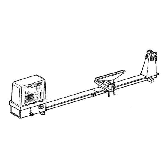
MODEL NO.
113.228360
WOOD LATHE
it
i liiii
,ii
lul
Serial
Number
Model and serial number
may be found on back of
headstock assembly.
You shouldrecordboth
model and serial n umber in
a safeplace forfuture use.
FOR YOUR
SAFETY'.
READ ALL
INSTRUCTIONS
CAREFULLY
CRAFTSMAN
12-INCH
WOOD LATHE
• assembly
• operating
• repair parts
J
Sears, Roebuck and Co., Hoffman Estates, IL 60179 U.S.A.
Part No, SP5110
Printed in U.S,A. 5195
Advertisement
Table of Contents

Related Manuals for Craftsman 113.228360


Summary of Contents for Craftsman 113.228360
- Page 1 113.228360 WOOD LATHE i liiii Serial Number Model and serial number may be found on back of headstock assembly. CRAFTSMAN You shouldrecordboth model and serial n umber in a safeplace forfuture use. 12-INCH WOOD LATHE FOR YOUR • assembly SAFETY'.
-
Page 2: General Safety Instructions For Power Tools
WOOD LATHE If within one year from the date of purchase, this Craftsman Wood Lathe fails due to a defect in material or workmanship, Sears will repair it, free of charge. WARRANTY SERVICE IS AVAILABLE BY SIMPLY CONTACTING THE NEAREST SEARS SERV- ICE CENTER/DEPARTMENT THROUGHOUT THE UNITED STATES. -
Page 3: Additional Safety Instructions For Wood Lathe
additional safety instructions for wood turning lathes Safety is a combination of common sense, staying alert WHEN INSTALLING MOVING and knowing how your lathe works. LATHE: BEFORE USING THE LATHE: 1. To avoid injury from unexpected lathe movement: Bolt the lathe to a stand or workbench that has WARNING: To avoid mistakes that could result in a rigid, flat surface for stability. -
Page 4: Whenever Lathe Is Running
1) Use both hands spaced apart and keep a 3) Make sure centers are aligned when firm hold of the turning toot. tailstock and ram are locked. 2) Always support the turning tool directly on 4) Make sure the spur center and cup center the tool rest. -
Page 5: Table Of Contents
glossary of terms Headstock Spur Center (Live Center) It is stationary at the left end of the bed.., contains Installed in the spindle of the headstock.., supports a spindle that the spur center fits into.,, provides the the workpiece on center at the headstock.., transfers power to rotate the workpiece. -
Page 6: Motor Specifications And Electrical Requirements
motor specifications and electrical requirements POWER SUPPLY WARNING: To maintain proper tool grounding whenever the outlet you are planning to use for this Motor Specifications power tool is of the two prong type, do not remove This wood lathe is designed to use the type motor or alter the grounding prong in any manner. -
Page 7: Unpacking And Checking Contents
unpacking and checking contents TABLE OF LOOSE PARTS WARNING: To avoid injury from unexpected start- Ing or electrical shock, do not plug the power ITEM DESCRIPTION QTY. cord into a source of power. This cord must Bed Machined ...... remain unplugged whenever you are working on Tool Rest 12 In ...... - Page 8 List of Loose Parts in Bag #507743 O Screw Soc. Hex 1/4-20 x 3/8 ..p Leckwasher 1/4 ..... Q Nut Hex 1/4-20 ..... R Screw Soc Cap 10o32 x 1 ..... S Bolt Hex HD 1/4-20 x 1 ....T Bolt Hex HD 114-20 x 1-1/2 ..
-
Page 9: Location And Function Of Controls
location and function of controls 1. ON-OFF SWITCH ..Turns lathe on and off and 13. TOOL REST HOLDER LOCK ..Locks the tool locks lathe in off position. rest holder to the tool rest slide. ,z_ -,_ 2. TOOL REST SLIDE ..Allows the tool rest to 14. -
Page 10: Assembly
assembly J ,,,, WARNING:To avoid Injury from unexpected lathe 118"HEX%? WRENCH movement and to provide necessary stability, 7t16" SOCKET 5f32" HEX "It' WRENCH mountthe lathe to a stationary work bench with a top at least i Inch thick. The lathe should be positioned on workbench approxi- 7t16"WRENCH SOCKET EXTENSION mately 6-1/2"... - Page 11 Place lathe bed near front of workbench in the posi- tion you want it to be permanently attached. The front of lathe bed should be positioned a minimum of 61/2 " from front edge of workbench and the work- bench must extend past both ends of lathe. PtJsh the two lathe bed sections tightly together where they meet.
- Page 12 9. From theloose parts bag locate a 114"x 1 -1/2" h ex head bolt,1/4"fiatwasher, 1/4"Iockwasher, and 114" hexnut,Place bolt t hrough c enter b edmount- ingbracket anddown through d rilled holein the workbench. Place fiat washer,Iockwasher, and hex nut onto bolt from underside of table and tighten. LOCK WASHER HEX NUT ILLUSTRATION SHOWS...
- Page 13 STRAIGHT EDGE 12. Hold straight edge tightly against bed sections. Lift up on bed sections until air gap between straight edge and bed sections disappears. The edge of straight edge will now be touching bed section along full length of straight edge. (See illustration.) If bolts that hold bed sections together have been STRAIGHT ADJUSTMENT...
-
Page 14: Mounting And Assembly Tool Rest
iHl,, TOOL REST SLIDE TOOL REST SLIDE LOCK MOUNTING AND ASSEMBLING TOOL REST ASSEMBLY 1. From the loose parts find the tool rest slide and tool rest slide lock. The shape and appearance of toot rest slide lock is as shown in illustration, Slide the tool rest slide onto right end of lathe bed. -
Page 15: Mounting And Assembling Tailstock
TOOL REST LOCK TOOL BEST TOOL From the loose parts locate the tool rest and tool rest lock. See illustration for appearance of tool rest LOCK lock. Set tool rest in tool rest holder and install tool rest lock as shown. REST LOCK ii ill... - Page 16 HANDWHEEL 3, From the loose parts locate the handwheel and GROOVE IN SPINDLE tailstock spindle. Place handwheel into tailstock as illustrated. SPINDLE GROOVE IN SPINDLE 4, Slide spindle through opening on right side of SPINDLE tailstockand thread spindle through handwheel as LOCK HOLE shown.
-
Page 17: Mounting And Assembling Headstock
HANDWHEEL 10/32" SOCKET HEAD SCREW 6, From the loose parts bag locate a 10/32 x 1" socket head screw, Screw the screw into the back side of the tailstock as shown, Failure to install this bolt will allow tailstock to slide off end of bed. Should it slide off accidentally and fall to the floor, damage to tailstock and cup center could result. - Page 18 3, Place a 5/32 °' hex wrench through round opening near power cord on backside of headstock. Insert hex wrench into set screw located 1-1/2" inside round opening. Tighten set screw securely using pliers on the end of the hex wrench. Check to see that headstock is securely attached to lathe bed by rocking the headstock assembly from left to right, and also up and down.
- Page 19 6. Placestraight e dge against s pindle pulley soone endofstraight edge is justabove thelarge section on motorpulley. W ithstraight e dgetouching full faceof spindle pulley, s lidespindlepulleyleftor rightuntilthe straight e dgeis in linewiththe left sideof motorpulley, (Seeillustration,) Keepboth STRAIG HT pulleysaligned with straight e dge,Usinga 118"...
-
Page 20: Installation Of Cup And Spur Centers
11.From theloosepartslocatea #6 x3/8phillips head screw(see illustration). U singa #2 phillips head MOTOR screwdriver install this motor cover stop screw, it is MOTOR COVER located on backside of headstock as shown in illust- COVER STOP SCREW ration. WARNING: the motor cover stop screw is for your protection, it prevents the motor cover from slid- ing back too far when moving belt for speed... - Page 21 3. Check and be sure that inside of headstock and tailstock spindles are clean. Insert spur center into headstock spindle and cup center into taitstock spindle. 1/4" DOWEL NOTE" Do not drive or hammer spur center and oup center into spindles as removal may be difficult. Use a soft hammer or block of wood and give them a gentle tap.
- Page 22 Lock the tailstock to the lathe bed by turning WARNING: Before using the iathe, test to make tailstock lock clockwise until tight. Scribe a line on sure headstock ls properly secured to lathe bed. the bed at right edge of headstock. Failure to properly secure headstock to lathe bed Rotate top of handwheel toward operator.
-
Page 23: Installation And Use Of On-Off Switch Key
INSTALLATION AND USE OF ON-OFF SWITCH KEY WARNING: Don't connect power cord to an elec- trical outlet until your lathe is mounted in its upright position. Failure to observe this warning may cause motor relay to burn out. ON-OFF SWITCH The On-Off Switch has a locking feature. -
Page 24: Basic Lathe Operation
basic lathe operation WARNING: To avoid Injury from unexpected start- ing, for your own safety, turn switch "off" and remove plug from power source outlet before making any adjustments or setups. CHANGING SPEEDS The belt is shown positioned on smallest motor pulley and largest spindle pulley. -
Page 25: Belt Tension Adustment
BELT TENSION ADJUSTMENT SLOT 1. Place belt tension adjustment lever in middle of long slot, BELT TENSION ADJUSTMENT LEVER" 2. Notice which lever support notch is immediately below belt tension adjustment lever. Place lever in this notch by pushing down and sideways on the lever, The lever is spring loaded so if belt slips during operation, place lever in next lower notch. -
Page 26: Mounting Wood For Spindle Turning
basic lathe operations MOUNTING WOOD FOR SPINDLE TURNING WARNING:To avoid Injury from unexpected start- Ing, turn switch "off" and remove switch key DIAGONAL before mounting workpieoe in lathe. LINES We recommended that spindle turnings larger than four Inches in diameter not be attempted. SPUR CENTER If you have not done a lot of wood turning, we suggest you start by mounting a small spindle turning. -
Page 27: Faceplate Turning
12. Adjust the tool rest approximately 1/8" away from the corners of the wood and 1/8" above the center line. Note the angled position of the tool rest base. WARNING: For your own safety, after adjusting • tool rest be sure and lock the tool rest holder, e tool rest slide and the tool rest. -
Page 28: Turning Tools
turning tools ROUND NOSE SKEW PARTINGTOOL SPEAR POINT FLAT NOSE GOUGE THE SiX COMMONLY USED CHISEL TYPES inches long to provide plenty of grip and leverage. Sharp A book entitled "Power Tool Know How Table Saw" is tools are essential for clean, safe work.., buy tools available at your nearest Sears Retail Store or Catalog that will take and hold clear edges. - Page 29 If you are removing wood from the diameter of a work- piece (as when turning the face of a faceplate turning) you must use a scraping action only.This is true because you are removing wood across the grain. Wood does not peel easily across the grain, and attempts to use a cutting action will result in damage to the workpiece and throwing of the chisel by the workpiece,...
-
Page 30: Maintenance
HOLDING THE WOODWORKING CHISEL WORK PIECE In handling alt turning tools, the handle hand takes a TOOL natural position, being nearer or farther from the end REST of the handle depending on the amount of leverage required. The position of the tool rest hand should be as illuslrated with turning tool held firmly against the tool rest and fingers and thumb wrapped around the turning tool on the opposite side of the tool rest, away... -
Page 31: Recommended Accessories
Sears recommends the following accessories ITEM CAT. NO ITEM CAT. NO. Work Bench ...... See Catalog Turning Tools ..... See Catalog Drill Chuck 1/2" Capacity with Draw Bolt with I/4"-20 Threads ..See Catalog No, 1 M,T, Shank ....See Catalog Power Tool Know-How Handbook .. - Page 32 trouble shooting TROUBLE SHOOTING -- MOTOR NOTE: Motors used on wood-working tools are particularly susceptible to the accumulation of sawdust and wood chips and should be blown out or "vacuumed" frequently to prevent interference with normal motor ventilation and proper operation of the centrifugally-operated starting switch.
- Page 33 NOTES...
- Page 35 _A,_J,5 LlSl _HAF /tAN lz"Wuuu LAIHE MODEL NO_13.228360 Always order by Part Number--Not by Key Number "I} Part Description Description Cover-Motor w/Labels 507816 941492O Washer 17/64 x 5/8 x 1/16 "o 816757 STD522525 * Screw-Hex HD. Housing-Fan Wheel-Turbine 816775 1/4-20x 2-1/2 816751 oMotor STD510803...
-
Page 36: Repairparts
_A/RS 12-1NCH owner's manual WOOD LATHE SERVICE Now that you have purchased your 12-inch Wood Lathe should a need ever exist for repair pads or service, simply contact any Sears Service Center and most Sears, Roebuck and Co. stores. Be sure to provide al! pertinent facts when you call or visit.