Hitachi L200 Series Service Manual
Hide thumbs
Also See for L200 Series:
- Instruction manual (281 pages) ,
- Quick reference manual (27 pages) ,
- Application note (2 pages)

Related Manuals for Hitachi L200 Series


Summary of Contents for Hitachi L200 Series
- Page 1 HITACHI INVERTER SERVICE MANUAL (ADJUSTMENT AND MAINTENANCE) After reading this manual, keep it at hand for future reference...
- Page 2 Appearance and name of each parts SJ200-002 - 007LFR SJ200-015 - 037LFR SJ200-004 - 037HFR potentiometer potentiometer digital operator digital operator front cover front cover top cover top cover housing housing cooling fin rear cover cooling fin rear cover ground ground The front cover can be removed without any instruments.
- Page 3 SJ200-055~075LFR SJ200-055~075HFR volume digital operator front cover top cover housing rear cover case cooling fin The front cover can be removed without any instruments When you remove the front cover, you can set the mode switch and set wire at the control-terminal, the main-terminal and the intelligent relay output terminal.
- Page 4 knob of potentiometer Note:The knob can be taken. digital operator communication connector for operator and RS-485 connector of digital operator POWER light ALARM light RUN light control-terminal A control-terminal B intelligent relay output terminal input logic switch main-terminal turning switch RS-485/Operator turning switch of frequency source and run command source...
- Page 5 L200-002~007LFR L200-015~037LFR connector cover connector cover L200-004~037HFR volume volume digital operator front cover digital operator front cover top cover top cover housing housing rear cover cooling fin rear cover cooling fin ground ground The front cover can be removed without any instruments. When you remove the front cover, you can set the mode switch and set wire at the control-terminal, the main-terminal and the intelligent relay、output terminal.
- Page 6 L200-055~075LFR L200-055~075HFR volume digital operator front cover top cover housing rear cover case cooling fin The front cover can be removed without any instruments. When you remove the front cover, you can set the mode switch and set wire at the control-terminal, the main-terminal and the intelligent relay output terminal.
- Page 7 (L200) The way to open the connector cover Removing the volume volume The volume can be removed communication connector L200-002~007LFR type L200-002~007LFR type Items inside frontcover L200-002~007LFR type mode switch control-terminal intelligent relay output terminal input logic switch main terminal turning switch RS-485/ Operator turning switch frequency source/...
- Page 8 Appearance The appearance of SJ200 follows below. OPE is a control unit. Formally OPE is attached to SJ200. But another OPE can be used optionally. This part is a logic circuit. It has a microcomputer, which does calculation of the I/O PCB (PCB3) intelligent input, output, communication task and so on...
-
Page 9: Inverter Specifications Label
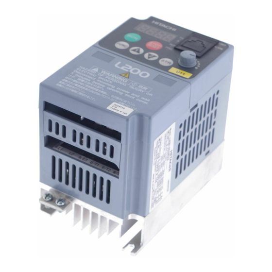
Introduction Inverter Specifications Label The Hitachi SJ200 inverters have product labels located on the right side of the housing, as pictured below. Be sure to verify that the specifications on the labels match your power source, motor, and application safety requirements. -
Page 10: Orientation To Inverter Features
2–2 Orientation to Inverter Features Orientation to Inverter Features Unpacking and Inspection Please take a few moments to unpack your new SJ200 inverter and perform these steps: 1. Look for any damage that may have occurred during shipping. 2. Verify the contents of the box include: a. -
Page 11: Inverter Keypad
2–3 SJ200 Inverter Inverter Keypad Keypad Removal - The SJ200 has a removable keypad. To remove the keypad, locate the retention latch as shown to the right. Press downward on the latch, while gently pulling toward you. The keypad will tilt forward, as two retaining tabs at the bottom edge of the keypad also hold it in place. - Page 12 2–4 Orientation to Inverter Features Front Housing Cover Housing Cover Removal - The front housing cover is held in place by two pairs of tabs. Since these are hidden from view, it is good to become familiar with their locations before attempting to remove the cover.
- Page 13 Removing the Cover (Slide type) 1. Press downward on the cover at the two areas indicated to release the retaining tabs. 2. Slide the cover forward and away from the keypad until the top edge of the cover reaches the notch in the inverter chassis.
- Page 14 2–5 SJ200 Inverter Logic Connector Locations - After removing the front housing cover, take a moment to become familiar with the connectors, as shown below. Relay output Logic inputs contacts Analog input/ output and logic outputs Logic Connector Removal/Replacement - The two 8-position main logic connectors are removable from the circuit board to make testing or service more convenient.
- Page 15 2–6 Orientation to Inverter Features Power Wiring Access - First, ensure no power source of any kind is connected to the inverter. If power has been connected, wait five minutes after powerdown and verify the Power LED is OFF to proceed. After removing the front housing cover, the housing partition that covers the power wiring exit will be able to slide upward as shown to the right.
- Page 16 B–4 Connecting the Inverter to ModBus OPE / 485 DIP Switch - The difference between OPE-S and OPE-Smini is the short-circuit inside the connector. If you set 485-side OPE-S,SRW says "----"(communication error) But OPE-Smini works properly.
-
Page 17: Parameter Settings For Keypad Entry
C–2 Introduction Introduction This section lists the user-programmable parameters for the SJ200 series inverters and the default values for European and U.S. product types. The right-most column of the tables is blank, so you can record values you have changed from the default. This involves just a few parameters for most applications. -
Page 18: Standard Functions
C–3 SJ200 Inverter Standard Functions “A” Group Parameters Default Setting User Func. -FEF Setting Name Code (EU) (USA) A001 Frequency source setting A002 Run command source setting A003 Base frequency setting 50.0 60.0 A203 Base frequency setting, 2nd 50.0 60.0 motor A004 Maximum frequency setting... - Page 19 C–4 Parameter Settings for Keypad Entry “A” Group Parameters Default Setting User Func. -FEF Setting Name Code (EU) (USA) A032 Multi-speed 12 setting A033 Multi-speed 13 setting A034 Multi-speed 14 setting A035 Multi-speed 15 setting A038 Jog frequency setting 1.00 1.00 A039 Jog stop mode...
- Page 20 C–5 SJ200 Inverter “A” Group Parameters Default Setting User Func. -FEF Setting Name Code (EU) (USA) A062 Frequency lower limit setting A262 Frequency lower limit setting, 2nd motor A063, Jump (center) frequency setting A065, A067 A064, Jump (hysteresis) frequency A066, width setting A068 A071...
- Page 21 C–6 Parameter Settings for Keypad Entry “A” Group Parameters Default Setting User Func. -FEF Setting Name Code (EU) (USA) A296 Dec1 to Dec2 frequency transi- tion point, 2nd motor A097 Acceleration curve selection A098 Deceleration curve selection A101 [OI]–[L] input active range start frequency A102 [OI]–[L] input active range end...
-
Page 22: Fine Tuning Functions
C–7 SJ200 Inverter Fine Tuning Functions “B” Group Parameters Default Setting User Func. -FEF Setting Name (EU) Code (USA) B001 Selection of automatic restart mode B002 Allowable under-voltage power failure time B003 Retry wait time before motor restart B004 Instantaneous power failure / under-voltage trip alarm enable B005 Number of restarts on power... - Page 23 C–8 Parameter Settings for Keypad Entry “B” Group Parameters Default Setting User Func. -FEF Setting Name (EU) Code (USA) B087 STOP key enable B088 Restart mode after FRS B090 Dynamic braking usage ratio B091 Stop mode selection B092 Cooling fan control B095 Dynamic braking control B096...
-
Page 24: Intelligent Terminal Functions
C–9 SJ200 Inverter Intelligent Terminal Functions “C” Group Parameters Default Setting User Func. -FEF Setting Name (EU) Code (USA) C001 Terminal [1] function C002 Terminal [2] function C003 Terminal [3] function C004 Terminal [4] function C005 Terminal [5] function C006 Terminal [6] function C011 Terminal [1] active state... - Page 25 C–10 Parameter Settings for Keypad Entry “C” Group Parameters Default Setting User Func. -FEF Setting Name (EU) Code (USA) C075 Communication stop bit selection C076 Communication error select C077 Communication erorr time-out 0.00 0.00 C078 Communication wait time C081 O input span calibration 100.0 100.0 C082...
-
Page 26: Motor Constants Functions
C–11 SJ200 Inverter Motor Constants Functions “H” Group Parameters Default Setting User Func. -FEF Setting Name Code (EU) (USA) H003 Motor capacity Specified Specified by the by the inverter inverter capacity capacity H203 Motor capacity, 2nd setting Specified Specified by the by the inverter inverter... -
Page 27: Troubleshooting
6–2 Troubleshooting Troubleshooting Safety Messages Please read the following safety messages before troubleshooting or performing mainte- nance on the inverter and motor system. WARNING: Wait at least five (5) minutes after turning OFF the input power supply before performing maintenance or an inspection. Otherwise, there is the danger of electric shock. -
Page 28: Troubleshooting Tips
6–3 SJ200 Inverter Troubleshooting Tips The table below lists typical symptoms and the corresponding solution(s). Symptom/condition Probable Cause Solution • • Is the frequency command source Make sure the parameter A001 parameter setting correct? setting A001 is correct. • • Is the Run command source A002 Make sure the parameter parameter setting correct? - Page 29 6–4 Troubleshooting Symptom/condition Probable Cause Solution • • If using the analog input, is the Check the wiring. current or voltage at [O] or [OI]? • Check the potentiometer or signal generating device. • • Is the load too heavy? Reduce the load.
-
Page 30: Monitoring Trip Events, History, & Conditions
6–5 SJ200 Inverter Monitoring Trip Events, History, & Conditions Fault Detection and Clearing The microprocessor in the inverter detects a variety STOP of fault conditions and captures the event, record- RESET Stop ing it in a history table. The inverter output turns OFF, or “trips”... - Page 31 6–6 Monitoring Trip Events, History, & Conditions Error Name Cause(s) Code E 1 1 CPU error A malfunction in the built-in CPU has occurred, so the inverter trips and turns OFF its output to the E 2 2 motor. E 1 2 External trip A signal on an intelligent input terminal configured as EXT has occurred.
-
Page 32: Trip History And Inverter Status
6–7 SJ200 Inverter Trip History and Inverter Status We recommend that you first find the cause of the fault before clearing it. When a fault occurs, the inverter stores important performance data at the moment of the fault. To access the data, use the monitor functions (Dxxx) and select D081 for details about the present fault (E ). -
Page 33: Restoring Factory Default Settings
6–8 Restoring Factory Default Settings Restoring Factory Default Settings You can restore all inverter parameters to the original factory (default) settings for the intended country of use. After initializing the inverter, use the powerup test in Chapter 2 to get the motor running again. To initialize the inverter, follow the steps below. Action Display Func./Parameter... - Page 34 EEPROM Compulsory Initialization All of EEPROM data are stored default setting -method- 1. After setting C091=01, store ‘**FF’ at EEPROM address 11d4(C092 setting). 2. Then press and hold the FUNC, UP, and DOWN key. POWER HITACHI ALARM STOP RESET FUNC 3.
- Page 35 ERROR Check error description No display DC bus charged IO board connection & cable connection OPE connection short bar P1- PD Cooling FAN failure Connection between IO board & OPE(L200) E08/E11 EEPROM recovery(initilalization display 11d4=ff) IO board connection & cable connection(communication error between ISPM &...
-
Page 36: Debug Mode
Debug Mode If you set debug mode enable (C091 =01), the function below will be available. When debugging, you can use only standard OPE (cannot use SRW) Make sure of returning C091=00 after debugging. There are some monitor or function-code for testing and maintenance which is not released for users. -
Page 37: Maintenance And Inspection
6–9 SJ200 Inverter Maintenance and Inspection Monthly and Yearly Inspection Chart Inspection Cycle Inspection Item Inspected Check for... Criteria Method Month Year ✔ Ambient Extreme Thermometer, Ambient temperature environment temperatures hygrometer between -10 to 40°C, & humidity non-condensing ✔ Major devices Abnormal Visual and aural Stable environment for... -
Page 38: Megger Test
6–10 Maintenance and Inspection Megger Test The megger is a piece of test equipment that uses a high voltage to determine if an insulation degradation has occurred. For inverters, it is important that the power termi- nals be isolated from the Earth GND terminal via the proper amount of insulation. The circuit diagram below shows the inverter wiring for performing the megger test. -
Page 39: Spare Parts
6–11 SJ200 Inverter Spare parts We recommend that you stock spare parts to reduce down time, including these parts: Quantity Part description Symbol Notes Used Spare Cooling fan 015NF, 022NF, 030LF, 015HF to 075HF Case • Front case • Key cover •... -
Page 40: General Inverter Electrical Measurements
6–12 Maintenance and Inspection General Inverter Electrical Measurements The following table specifies how to measure key system electrical parameters. The diagrams on the next page show inverter-motor systems and the location of measurement points for these parameters. Circuit location Measuring Parameter Notes Reference Value... - Page 41 6–13 SJ200 Inverter The figures below show measurement locations for voltage, current, and power measure- ments listed in the table on the previous page. The voltage to be measured is the funda- mental wave effective voltage. The power to be measured is the total effective power. Single-phase Measurement Diagram Inverter Motor...
-
Page 42: Inverter Output Voltage Measurement Techniques
6–14 Maintenance and Inspection Inverter Output Voltage Measurement Techniques Taking voltage measurements around drives equipment requires the right equipment and a safe approach. You are working with high voltages and high-frequency switching waveforms that are not pure sinusoids. Digital voltmeters will not usually produce reliable readings for these waveforms. -
Page 43: Igbt Test Method
6–15 SJ200 Inverter IGBT Test Method The following procedure will check the inverter transistors (IGBTs) and diodes: 1. Disconnect input power to terminals [R, S, and T] and motor terminals [U, V, and W]. 2. Disconnect any wires from terminals [+] and [RB] for regenerative braking. 3. - Page 44 The following series inverter is equipped a cooling fan. (200V class): 1,5kW, 2.2kW, 3.7kW (400V class): 1,5kW, 2.2kW, 3.7kW A way to replace the fan follows below. By the way, primary released product is different from not primary (secondly -) one about the way to remove the fan.
- Page 45 There are several ways which depend on the scale of the housing cover. scale (small) : (200V class ) 0.2kW, 0.4kW, 0.75kW scale (middle): (200V class ) 1.5kW, 2.2kW, 3.7kW (400V class ) 0.4kW – 3.7kW Scale (small) 1.Remo ve the mon itor cover, front cover and rear cover. When remov in g the mon itor cover, p lease remove the co mmun ication cab le from t he front cover s ide.
- Page 46 1.Remo ve the mon itor cover, front cover and rear cover. When remov in g the mon itor cover, p lease remove the co mmun ication cab le from t he front cover s ide. fr o n t c ove r mo ni tor c o v e r r e a r c ov e r ho us i n g...
- Page 47 3.Insert the minus screw driver between the cooling fin and the housing, and unlock the tabs (4 points at the left and right side. ta b1 ta b3 ta b2 ta b4 4. Remove the housing.
- Page 48 Scale (large) ① Remove the monitor cover, front cover and rear cover. When removing the monitor cover, please remove the communication cable from the front cover side. f r o n t c o v e r m o n i t o r c o v e r r e a r c o v e r ②...
- Page 49 ③ Remove the housing h o u s i n g 4-15...
- Page 54 5.1.構造図(5/11)
- Page 55 5.1.構造図(6/11)
- Page 56 5.1.構造図(7/11)
- Page 57 5.1.構造図(8/11)
- Page 58 5.1.構造図(9/11)
- Page 59 5.1.構造図(10/11) 5-10...
- Page 60 5.1.構造図(11/11) 5-11...