Table of Contents
Advertisement
Advertisement
Table of Contents

Related Manuals for Panasonic WV-CP504


Summary of Contents for Panasonic WV-CP504
-
Page 1: Installation Guide
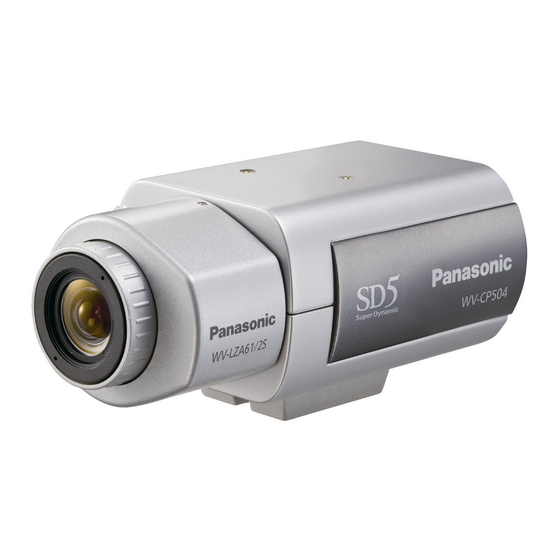
Installation Guide Color CCTV Camera WV-CP500 Model Nos. WV-CP504 This illustration represents WV-CP500. Lens: Option Before attempting to connect or operate this product, please read these instructions carefully and save this manual for future use. No model number suffix is shown in this manual. - Page 2 WARNING: • This apparatus must be earthed. • Apparatus shall be connected to a mains sock- et outlet with a protective earthing connection. • The mains plug or an appliance coupler shall remain readily operable. • To prevent fire or electric shock hazard, do not expose this apparatus to rain or moisture.
-
Page 3: Important Safety Instructions
Important safety instructions 1) Read these instructions. 2) Keep these instructions. 3) Heed all warnings. 4) Follow all instructions. 5) Do not use this apparatus near water. 6) Clean only with dry cloth. 7) Do not block any ventilation openings. Install in accordance with the manufacturer's instructions. -
Page 4: Limitation Of Liability
Disclaimer of warranty (5) ANY PROBLEM, CONSEQUENTIAL IN NO EVENT SHALL Panasonic Corporation B E L I A B L E T O A N Y PA R T Y O R A N Y INCONVENIENCE, OR LOSS OR DAM-... -
Page 5: Preface
This product is a 1/3-inch type {1/3"} CCD color CCTV camera. Connection of this product to a video monitor allows users to use this product as a monitoring camera. • WV-CP500: 120 V AC power supply • WV-CP504: 24 V AC, 12 V DC power supply Introduction of SUPER-D5 (super dynamic function) Integration of SUPER-D5 into the CCD and signal processing circuit has achieved approximate- ly 128 times higher dynamic range as compared with conventional camera. -
Page 6: About The User Manuals
About the user manuals The operating instructions of the camera consist of 2 sets: this book and operating instructions (PDF). This book explains how to install the camera. Refer to the "Operating Instructions (PDF)" on the provided CD-ROM for descriptions of how to ®... -
Page 7: Table Of Contents
Contents Important safety instructions....................... 3 Limitation of liability ........................4 Disclaimer of warranty ........................ 4 Preface ............................5 About the user manuals......................6 Trademarks and registered trademarks ..................6 Precautions..........................8 Major operating controls and their functions................9 Precautions for installation ......................12 Installation and connection ...................... -
Page 8: Precautions
Power is supplied from an external 12 V DC/ cleaning this product. When the dirt is hard 24 V AC (WV-CP504) or 120 V AC (WV- to remove, use a mild detergent and wipe CP500) power-supply device. Refer to ser- gently. -
Page 9: Major Operating Controls And Their Functions
* The following names are assigned to (DOWN) each button in this book: : Up button (UP) : Down button (DOWN) : Left button (LEFT), NEAR : Right button (RIGHT), FAR : Setting button (SET), BF/MENU Side view (WV-CP504) ALC lens connector Tripod mount base... - Page 10 Rear view (WV-CP500) External terminal Power indicator ALARM OUT POWER ALARM IN Video output connector VIDEO OUT 120V ~ 60Hz Power connector Rear view (WV-CP504) External terminal ALARM OUT Power indicator VIDEO OUT POWER ALARM IN (UP) Operation buttons* NEAR...
- Page 11 Tripod mount base AC/DC power terminal This socket is used to mount the camera (only for WV-CP504) mount bracket (option). The tripod socket The power supply of 24 V AC or 12 V DC is can be mounted on either top or bottom of connected to this terminal.
-
Page 12: Precautions For Installation
Installation near an air conditioner, an air humidity below 90 %.The input power source cleaner, a vending machine, or the like is 12 V DC/24 V AC (WV-CP504) or 120 V AC causes noise. (WV-CP500). Avoid connections during a lightning Installing place storm. - Page 13 Power cord (only for WV-CP500) Connect the power cord securely. Run the power cord so that no load is applied to the cord when panning or tilting the camera. (Failure to observe this may disconnect the power cord, and accordingly no image is dis- played.)
-
Page 14: Installation And Connection
Installation and connection Cautions: • ONLY CONNECT WV-CP504 TO 24 V AC OR 12 V DC CLASS 2 POWER SUPPLY. • Be sure to connect the grounding lead to the GND terminal. Rotate the lens (option) clockwise slowly to mount the lens. Important: • For use of C-mount lens, use the C-mount adaptor (option). • For prevention of damage to the camera body, use a lens with protrusion of 5.5 mm {7/32"} or less from the flange surface. Protrusion from flange: 5.5 mm {7/32"} or less Optional dedicated lens Lens type Model Nos. - Page 15 Connect the lens cable to the ALC lens connector of the camera. ALC lens connector Pin No. Brake @ Brake ! Drive ! Drive @ Secure the camera mount bracket <Installation sample on a ceiling> (option) to an installation position, and mount the camera on the camera mount Camera mount bracket (option)
- Page 16 • The mounting conditions of the camera mount bracket are described as follows: Applicable mount Recommended Number of Minimum pull-out Installation place bracket screw screw strength (per 1 pc.) On ceiling WV-7011 4 pcs. 196 N {44.06 lbf} WV-7010 3 pcs. 196 N {44.06 lbf} WV-7012 3 pcs. 196 N {44.06 lbf} On wall WV-831 4 pcs.
- Page 17 The video output cable is connected to this video output connector. Important: • Be sure to turn off the power of each device before connection. • Be sure to secure the coaxial cable connectors. Connect a coaxial cable to the video output connector. Coaxial cables ALARM OUT POWER ALARM IN To video input VIDEO OUT 120V ~ 60Hz WV-CP500 Use a cable tie (locally procured) to attach the coaxial cable to the camera mount bracket.
-
Page 18: External Synchronization Switch
(3 to 5 V DC, internally The external terminal is the same between pulled up) WV-CP500 and WV-CP504. Off: Open or 3 to 5 V DC On: Make contact with GND (required drive current: 0.2 mA or more) - Page 19 Connect between the power connector on the rear side of the camera and a plug socket with the supplied power cord. ALARM OUT POWER ALARM IN Power cord (accessory) VIDEO OUT 120 V AC 60 Hz 120V ~ 60Hz WV-CP504 ALARM OUT VIDEO OUT POWER ALARM IN Important: (UP) NEAR BF/MENU • The power supply of 24 V AC/12 V DC shall...
- Page 20 Adjust the camera angle by loosening the screw of the camera mount bracket while viewing the video monitor. Be sure to loosen the screw of the camera mount bracket when the camera angle is adjust- ed. If the camera angle is changed when the screw is tight, excessive force is applied to the camera mount bracket and camera, and accordingly they may be damaged.
- Page 21 (The variation in illuminance is not followed after focus adjust- ment.). • When a non-Panasonic lens that has an extended range for lens focusing is used, adjust the back focus after setting the focus to a position at a short distance from the FAR end. If adjustment is performed in the extended range, appropriate adjustment...
-
Page 22: Setup Menu
Setup menu Performing each setting item in the setup menu should be completed in advance to use this unit. Perform the settings for each item in accordance with the conditions of the camera shoot- ing area. Refer to the operating instructions (PDF) for further information. List of setup menu Setup item Description... - Page 23 Setup item Description SPECIAL CHROMA GAIN Adjusts the chroma level. AP GAIN Adjusts the aperture level. PEDESTAL Adjusts the pedestal (brightness) level. Adjusts the chroma phase (hue). PIX OFF Corrects image defects such as flaws. COMMUNICATION Performs the communication setting of the system with a receiver into which this unit is integrated.
-
Page 24: Basic Operation
Basic operation The description below explains how to operate the setup menu basically. The operations in the setup menu are performed with the operation buttons (☞ pages 9 and 10) after calling up the setup menu on the connected video monitor. The operations in the setup menu can also be performed through the system controller (option). - Page 25 Screenshot 3 The selected setup screen in the setup menu Step 4 appears on the screen. Perform the settings for each item. • Selection of setting item: **CAMERA SETUP** Press the up button or down button to SCENE1 ALC/ELC move the cursor. SHUTTER • Change of settings: ON(HIGH) SENS UP...
-
Page 26: Screen Transition Diagram
Screen transition diagram Top screen "CAMERA ID" screen MODEL WV-CP500 SERIES **CAMERA ID** CAMERA ID 0123456789 CAMERA ABCDEFGHIJKLM SYSTEM NOPQRSTUVWXYZ BACK-FOCUS ().,'":;&#!?= SPECIAL +-*/%$ LANGUAGE SPACE POSI RET TOP END RESET ....SETUP ENABLE "CAMERA SETUP" screen **CAMERA SETUP** SCENE1 ALC/ELC SHUTTER ON(HIGH) -
Page 27: Troubleshooting
Troubleshooting Before asking for repairs, check the symptoms with the following table. Contact your dealer if a problem cannot be solved even after checking and trying the solution in the table or a problem is not described below. Reference Symptom Cause/solution pages •... - Page 28 Inspect the power cord, power plug and power connectors periodically. Reference Symptom Cause/solution pages Damaged power cord sheathing • The power cord, power connector, or power plug is damaged. Heated portion of power Use of the damaged cord, connector, line consisting of power cord, connector, and or plug may cause electric shock or –...
-
Page 29: Specifications
WV-CP504: 24 V AC 60 Hz, 12 V DC Power consumption: WV-CP500: 3.2 W WV-CP504: 24 V AC: 3.6 W, 12 V DC: 310 mA Ambient operating temperature: –10 °C to +50 °C {14 °F to 122 °F} Ambient operating humidity: Less than 90 % (non condensing) VBS: 1.0 V [p-p]/75 Ω, NTSC, BNC connector... -
Page 30: Standard Accessories
Operating Instructions (this book) ....1 pc. Warranty card ..........1 pc. *The CD-ROM contains the operating instructions (PDF). The following parts are used during installation procedures. Power connector (only for WV-CP500) ... 1 pc. Power cord plug (only for WV-CP504) ... 1 pc. - Page 32 Panasonic System Solutions Company, Unit Company of Panasonic Corporation of North America www.panasonic.com/business/ For customer support, call 1.800.528.6747 Three Panasonic Way 2H-2, Secaucus, New Jersey 07094 Panasonic Canada Inc. 5770 Ambler Drive, Mississauga, Ontario, L4W 2T3 Canada (905)624-5010 http://www.panasonic.ca Panasonic Sales Company Panasonic Puerto Rico, Inc.