Panasonic WV-CP500 Operating Instructions Manual
Color cctv camera
Hide thumbs
Also See for PANASONIC WV-CP500:
- Installation manual (32 pages) ,
- Specification (2 pages) ,
- Product catalog (125 pages)
Table of Contents
Advertisement
Operating Instructions
Color CCTV Camera
WV-CP500
Model No.
WV-CP504
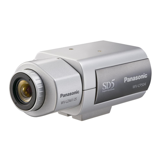
This illustration represents WV-CP500.
Lens: Option
Before attempting to connect or operate this product,
please read these instructions carefully and save this manual for future use.
No model number suffix is shown in this manual.
Advertisement
Table of Contents

Related Manuals for Panasonic PANASONIC WV-CP500


Summary of Contents for Panasonic PANASONIC WV-CP500
-
Page 1: Operating Instructions
Operating Instructions Color CCTV Camera WV-CP500 Model No. WV-CP504 This illustration represents WV-CP500. Lens: Option Before attempting to connect or operate this product, please read these instructions carefully and save this manual for future use. No model number suffix is shown in this manual. -
Page 2: Preface
Preface About the user manuals The operating instructions of the camera consist of 2 sets: these operating instructions (PDF) and Installation Guide. This document explains how to configure the settings of the camera. Refer to the installation guide for further information about how to install the camera. ®... -
Page 3: Table Of Contents
Preface ... 2 About the user manuals ... 2 Trademarks and registered trademarks ... 2 About the setup menus... 4 Setup menu list ... 4 Basic operation ... 5 Screen transition diagram ... 6 Camera title setting [CAMERA ID] ... 7 Camera operation setting [CAMERA SETUP] ... -
Page 4: About The Setup Menus
About the setup menus Performing each setting item in the setup menu should be completed in advance to use this unit. Perform the settings for each item in accordance with the conditions of the camera shooting area. The following is an example of setup procedure when LANGUAGE is set to ENGLISH. Setup menu list Setup item This item specifies the camera title. -
Page 5: Basic Operation
Basic operation The description below explains how to operate the setup menu basically. The operations in the setup menu are performed with the operation buttons after calling up the setup menu on the connected video monitor. Refer to the installation guide for further information about the operation buttons. The operations in the setup menu can also be performed through the system controller (option). -
Page 6: Screen Transition Diagram
Screen transition diagram Top screen MODEL WV-CP500 SERIES CAMERA ID CAMERA SYSTEM BACK-FOCUS SPECIAL LANGUAGE SETUP ENABLE "CAMERA ID" screen **CAMERA ID** 0123456789 ABCDEFGHIJKLM NOPQRSTUVWXYZ ().,'":;&#!?= +-*/%$ SPACE POSI RET TOP END RESET "CAMERA SETUP" screen **CAMERA SETUP** SCENE1 ALC/ELC SHUTTER ON(HIGH) SENS UP... -
Page 7: Camera Title Setting [Camera Id]
Camera title setting [CAMERA ID] This item specifies the camera title. The camera title that indicates the camera location and other information about the camera is created with alphanumerics and symbols, and is displayed on the screen. The camera title is named with up to 16 characters. Follow the procedure below to specify the camera title. -
Page 8: Camera Operation Setting [Camera Setup]
Camera operation setting [CAMERA SETUP] The following describes the camera operation settings. The following settings can be configured on the "CAMERA SETUP" screen displayed from the top screen. Refer to page 5 for how to call up the screen. The settings configured on the "CAMERA SETUP" screen will be saved as a scene file. 1. -
Page 9: Light Quantity Control Method Selection [Alc/Elc]
Step 5 Move the cursor to "SCENE1" and press the right or left button to select "SCENE1" to resume normal operation. Important: • When "SCENE2" is set for "ALARM IN", the "SCENE X (EXT)" indication will be displayed and it is impossible to change the scene file. * X indicates "1" or "2". 2. Light quantity control method selection [ALC/ELC] The method of controlling the quantity of light is selected from the following in accordance with the lens to be used. ALC (default): The iris of the lens is automatically adjusted in accordance with the brightness of a subject. Select "ALC" when using the SUPER-D5 function or when using an ALC lens. Refer to the following when configuring the SUPER-D5 settings. ALC+: Controls the quantity of light with a combination of the electronic shutter and auto iris. This selection is suitable at shoot- ing a bright subject such as an outdoor subject with auto iris lens. Be aware that flicker may occur when a subject is under fluorescent lighting. - Page 10 Step 2 Move the cursor to "SUPER-D5" and select the item from the following: ON (default): Activates the SUPER-D5 function all the time. (+ See below) ON (i-VMD): Activates the SUPER-D5 function all the time. (+ See below) In addition to the SUPER-D5 function, the motion detection function also works. OFF: Deactivates the SUPER-D5 function.
-
Page 11: Electronic Shutter Setting [Shutter]
When not using the SUPER-D5 function Follow the procedure below. Step 1 When the SUPER-D5 function is set to "OFF", bright areas of an image are masked to facilitate the visibility of dark areas. Move the cursor to "MASK SET" and press the setting button. → The mask setting screen appears. "ALC CONT" screen **ALC CONT**(1) BACK LIGHT COMP SUPER-D5 MASK SET ... | ... 0 LEVEL MANUAL ABS RET TOP END Step 2 Mask bright areas. Use the up, down, right, and left buttons to select an area to be masked and press the setting button. When the selected area is masked, the masked area will start blinking (between stripes and white screen). When selecting another area after masking, the masked area will be edisplayed in white. Repeat the above procedure to mask other areas as necessary. Note: • To cancel the masking, select the masked area to be canceled, and then press the setting button. -
Page 12: Gain Control Setting [Agc]
When the SUPER-D5 function is set to "OFF": OFF (1/60) (default), 1/100, 1/250, 1/500, 1/1 000, 1/2 000, 1/4 000, and 1/10 000 When the SUPER-D5 function is set to "ON" or "ON(i-VMD)": OFF (1/60) (default), 1/100 Note: • When "ALC/ELC" is set to "ELC" or "ALC+" (+ page 9), "---" appears and the electronic shutter function cannot be activated. • If the controller, WV-CU254 or WV-CU204 is used, SW LED and the status of "SHUTTER" are not correctly displayed. - Page 13 Note: If the situation meets one of the following or other, color may not be accurately reproduced. • The subject is mostly highly-colored. • The photographic atmosphere is under the bright blue sky or at nightfall. • The illumination of the light illuminating the subject is insufficient. ATW2: Activates the sodium lamp automatic color temperature tracking mode. The camera automatically achieves an optimal white balance under the sodium lamp. The adjustment of the color temperature ranges from approx. 2 000 K to 6 000 K. AWC: Activates the automatic white balance control mode.
-
Page 14: Manual Fine Adjustment Of White Balance
Manual fine adjustment of white balance The white balance is manually fine adjusted after white balance automatically adjustment in the automatic color temperature tracking mode (ATW1, ATW2) or automatic white balance control mode (AWC). Follow the procedure below. "CAMERA SETUP" screen **CAMERA SETUP** SCENE1 ALC/ELC... - Page 15 Step 1 Move the cursor to "BW MODE" and select the black-and-white control from the following: AUTO1 (default): Automatically toggles between color and black-and-white images in accordance with the screen brightness (illuminance). The black-and-white mode is selected for dark images, and the color mode is selected for bright images. AUTO2: Uses a near-infrared light source at nighttime.
-
Page 16: I-Vmd Setting [I-Vmd]
9. i-VMD setting [i-VMD] The intelligent motion detection function allows the camera to detect motion and appearance/disappearance of an object or scene change with the camera. Detection of motion and appearance/disappearance of an object or scene change with the camera can be announced by issuing an alarm signal or displaying a frame on the screen. Important: • The following circumstances may result in detection failure or false detection: Adjusting the detection area and sensitivity may cause detection failure. - Page 17 Detect motion of objects Move the cursor to "MOTION" and select from the following. ON: Provides an alarm signal when motion is detected. OFF (default): Does not detect motion. Detect objects that move continuously within a specified period Move the cursor to "LOITERING" and select the duration from the following: When a continuously moving object is detected within a specified period, an alarm signal is issued.
-
Page 18: Perform The Settings Relating To The Detection Of Appearance/Disappearance Of Stationary Objects
Perform the settings relating to the detection of appearance/disappearance of stationary objects Perform the settings relating to the detection of appearance/disappearance of stationary objects as follows. Up to 4 appearanc- es/disappearances of stationary objects can be simultaneously detected. However, use of the scene change detection function decreases the maximum simultaneous detectable appearances/disappearances of stationary objects to 3. -
Page 19: Set The Detection Areas
Set the detection areas Set the detection areas for motion detection and the detection of appearance/disappearance of stationary objects. Up to 2 detection areas can be set. Follow the procedure below. "MOTION DET" screen **MOTION DET**(1) MOTION LOITERING DIRECTION AREA SETUP SENSITIVITY RET TOP END... -
Page 20: Setting Of Scene Change Detection
Setting of scene change detection This function detects a change in the subject state that occurs by covering the camera with a cloth, a cap, or others, or by changing the camera direction largely. Follow the procedure below. "CAMERA SETUP" screen **CAMERA SETUP** SCENE1 ALC/ELC... -
Page 21: Configure Alarm Notification
Configure alarm notification Follow the procedure below. "CAMERA SETUP" screen **CAMERA SETUP** SCENE1 ALC/ELC SHUTTER ON(HIGH) SENS UP WHITE BAL ATW1 HIGH BW MODE AUTO1 i-VMD RET TOP END Step 1 Move the cursor to "i-VMD" and press the setting button. →... -
Page 22: Camera System Setting [System Setup]
Camera system setting [SYSTEM SETUP] Performs the settings relating to the camera system such as synchronization, alarm input/output terminal, and privacy zone. The following settings can be configured on the "SYSTEM SETUP" screen displayed from the top screen. Refer to page 5 for how to call up the screen. -
Page 23: Alarm Input/Output Terminal Setting [Alarm In/Out]
Step 1 Set "SYNC" to "LL" and press the setting button. → The "SYNC" screen appears. Step 2 Connect the video output signal and external synchronizing input signal of the camera to a 2-input oscilloscope, and move the cursor to "COARSE". Step 3 Adjust the oscilloscope to the vertical rate, and extend the vertical synchronizing part of the oscilloscope. -
Page 24: Configure The Settings Relating To The Alarm Output Terminal
Configure the settings relating to the alarm output terminal Select the alarm output operation. Follow the procedure below. "SYSTEM SETUP" screen **SYSTEM SETUP** SYNC ALARM IN/OUT PRIVACY ZONE STABILIZER EL-ZOOM RET TOP END Step 1 Move the cursor to "ALARM IN/OUT" and press the setting button. →... -
Page 25: Image Stabilizer Setting [Stabilizer]
Step 2 Move the cursor to the number at the right of the title and select the zone number using the right or left button. Step 3 Move the cursor to "POSITION" and press the setting button. Step 4 Use the up, down, right, and left buttons to determine the left upper position of the zone to be set and press the setting button. Step 5 Use the up, down, right, and left buttons to determine the lower right position of the zone to be set and press the setting button. -
Page 26: Electronic Zoom Setting [El-Zoom]
14. Electronic zoom setting [EL-ZOOM] Select "On" or "Off" to determine whether or not to use the electronic zoom. When "ON" is selected, the zoom factor and the panning/tilting settings can be configured. ON: Uses the electronic zoom. OFF (default): Does not use the electronic zoom. Follow the procedure below. -
Page 27: Back Focus Setting [Back-Focus Setup]
Back focus setting [BACK-FOCUS SETUP] Selects the back focus setting type and performs fine adjustment. The following setting can be configured on the "BACK- FOCUS SETUP" screen displayed from the top screen. Refer to page 5 for how to call up the screen. The lens adjustment (☞... - Page 28 Step 3 Move the cursor to "C/L ← → B/W" and select the back focus adjustment type from the following: AUTO (default): Adjusts the back focus function automatically and corrects out of focus when switching between color and black-and-white images. PRESET: Performs the preset movement to each specified back focus position when switching between color and black-and- white images.
-
Page 29: Special Menu Setting [Special Setup]
Special menu setting [SPECIAL SETUP] The special menu setup is performed including the setting of the camera image quality and the communication configuration when a receiver is used. The following settings are to be configured on the "SPECIAL SETUP" screen displayed from the top screen. -
Page 30: Flaw Compensation [Pix Off]
Flaw compensation [PIX OFF] Flaws in the displayed camera image are corrected. Up to 16 points can be corrected. Follow the procedure below. "SPECIAL SETUP" screen **SPECIAL SETUP** ...128 CHROMA GAIN ... 32 AP GAIN ... 32 PEDESTAL PIX OFF COMMUNICATION COAX CAMERA RESET PUSH SW... -
Page 31: Communication Setting [Communication]
Communication setting [COMMUNICATION] The required communication configuration is performed to use this unit integrated into the system with a receiver. COAX (RCV): Select COAX (RCV) when using our receiver (e.g. WV-RC100 or WV-RC150). COAX (default): Does not use any receiver. Default resetting [CAMERA RESET] The settings in the setup menu are restored to the default settings. -
Page 32: Language Selection [Language Setup]
Language selection [LANGUAGE SETUP] A language for the setup menu is selected from the following: The language selection can be made on the "LANGUAGE SETUP" screen displayed from the top screen. Refer to page 5 for how to call up the screen. JAPANESE/ENGLISH (default)/FRANÇAIS/ESPAÑOL/DEUTSCH/ITALIANO/РУССКИЙ... -
Page 33: Shortcut Operation
Shortcut operation Use of a system controller with the "camera function" button allows users to perform the shortcut settings with use of the numeric keypad and camera function button. The available shortcut operations with this unit are shown as follows: System controller operation [8] + [3] + [Camera function] [8] + [4] + [Camera function]... - Page 34 System controller operation [2] + [1] + [1] + [Camera function] [2] + [1] + [2] + [Camera function] [2] + [1] + [3] + [Camera function] [2] + [1] + [4] + [Camera function] [2] + [1] + [5] + [Camera function] [2] + [1] + [6] + [Camera function] Setting contents Scene change ON Scene change OFF Scene file 1 Scene file 2 Gain (AGC), 1 step up Gain (AGC), 1 step down...
- Page 35 Panasonic System Solutions Company, Unit Company of Panasonic Corporation of North America www.panasonic.com/business/ For customer support, call 1.800.528.6747 Three Panasonic Way 2H-2, Secaucus, New Jersey 07094 Panasonic Canada Inc. 5770 Ambler Drive, Mississauga, Ontario, L4W 2T3 Canada (905)624-5010 http://www.panasonic.ca © Panasonic Corporation 2009 Panasonic Sales Company Panasonic Puerto Rico, Inc.