Table of Contents
Advertisement
Advertisement
Table of Contents

Related Manuals for Cisco SR520-FE-K9


Summary of Contents for Cisco SR520-FE-K9
- Page 1 ADMINISTRATION GUIDE Cisco SRP500 Series Services Ready Platforms (SRP520 Models)
-
Page 2: Wps Method
Cisco and the Cisco Logo are trademarks of Cisco Systems, Inc. and/or its affiliates in the U.S. and other countries. A listing of Cisco's trademarks can be found at www.cisco.com/go/trademarks. Third party trademarks mentioned are the property of their respective owners. The use of the word partner does not imply a partnership relationship between Cisco and any other company. -
Page 3: Table Of Contents
Configuration Utility Icons Chapter 3: The Quick Setup Menu Basic Configuration Setup WAN Setup (Ethernet) WAN Setup (ADSL) LAN Setup Wireless Setup Remote Provisioning Advanced Configuration Setup Voice Mobile Network Setup Cisco SRP500 Series Services Ready Platforms Administration Guide (SRP520 Models) - Page 4 Wireless Protected Setup WPS Method 1 WPS Method 2 WPS Method 3 Wireless MAC Filter Advanced Wireless Settings WMM Setting Using the Management Interface Chapter 5: Configuring the Network Routing Static Routes Cisco SRP500 Series Services Ready Platforms Administration Guide (SRP520 Models)
- Page 5 Supported Codecs SIP Proxy Redundancy Other SRP Voice Features Registering to the Service Provider Managing Caller ID Services Optimizing Fax Completion Rates Fax Troubleshooting Silence Suppression and Comfort Noise Generation Cisco SRP500 Series Services Ready Platforms Administration Guide (SRP520 Models)
- Page 6 Line Status System Page System Configuration Miscellaneous Settings SIP Page SIP Parameters SIP Timer Values Response Status Code Handling RTP Parameters SDP Payload Types NAT Support Parameters Provisioning Page Configuration Profile Cisco SRP500 Series Services Ready Platforms Administration Guide (SRP520 Models)
- Page 7 FXS Port Polarity Configuration User Pages (1–2) Call Forward Settings Selective Call Forward Settings Speed Dial Settings Supplementary Service Settings Distinctive RIng Settings Ring Settings Chapter 7: Configuring VPN IKE Policy IPSec Policy Cisco SRP500 Series Services Ready Platforms Administration Guide (SRP520 Models)
- Page 8 Factory Defaults Firmware Upgrade Backup & Restore Backup Configuration Restore Configuration Reboot Status Switch Setting Chapter 9: Using Services Ready Platform Diagnostics Ping Test Traceroute Test Detect Active LAN Clients Cisco SRP500 Series Services Ready Platforms Administration Guide (SRP520 Models)
- Page 9 Mobile Network Status DHCP Server Information QoS Status Routing Table ARP Table RIP Status IGMP Status VPN Status CDP Neighbor Information Appendix A: Specifications Appendix B: Where to Go From Here Cisco SRP500 Series Services Ready Platforms Administration Guide (SRP520 Models)
-
Page 10: Chapter 1: Introducing The Srp500 Series Services Ready Platform
• Product Overview For information about how to physically install the SRP and how to use the Setup Wizard to initially configure it, see the Cisco SRP500 Series Services Ready Platforms Quick Start Guide (SRP520 Models) at www.cisco.com/go/srp500resources. Feature Overview Thank you for choosing the Cisco Services Ready Platform SRP 500 Series (SRP520 Models). -
Page 11: Product Overview
4 LAN (10/100) ports, 1 USB 2.0 port, 802. 1 1n, and WiFi Protected Setup (WPS) Front Panel SRP521W Front Panel Cisco Small Business Pro SRP 521W POWER/SYS WLAN PHONE WLAN Cisco SRP500 Series Services Ready Platforms Administration Guide (SRP520 Models) -
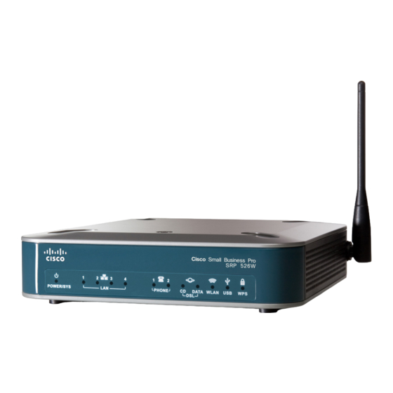
Page 12: Srp526W / Srp527W Front Panel
Flashes if there is a device failure or unsupported device. WPS button Lights when WiFi Protected Setup (WPS) is operational. A slow green flash indicates that the setup is in progress. A fast green flash indicates a setup error. Cisco SRP500 Series Services Ready Platforms Administration Guide (SRP520 Models) -
Page 13: Back Panel
(FXS) Ports power Ports SRP526W / SRP527W Back Panel Line (FXO) On/Off Port Switch PHONE (FXS) LINE (FXO) LAN/WAN LAN (10/100) Phone 12 V DC Port (FXS) power Ports Ports Cisco SRP500 Series Services Ready Platforms Administration Guide (SRP520 Models) -
Page 14: Back Panel Descriptions
LAN (10/100) ports (1–4) Connects to a wired computer and other network devices. On/Off Switch Powers the SRP on or off. 12 V DC power Connects to the provided power adapter. Cisco SRP500 Series Services Ready Platforms Administration Guide (SRP520 Models) -
Page 15: Side View
To press the button, insert a paper clip or similar object into the opening USB port Connects to a compatible USB Modem. For information about connecting the SRP to a USB see Mobile Network, page Antenna The WiFi antenna. Cisco SRP500 Series Services Ready Platforms Administration Guide (SRP520 Models) -
Page 16: Top View
WiFi Protected Setup (WPS). To configure WPS, press and hold this button until the WPS light flashes. Make sure that the device is located near the SRP during setup. Cisco SRP500 Series Services Ready Platforms Administration Guide (SRP520 Models) -
Page 17: Default Settings
Admin Password admin DHCP Range 192. 1 68. 1 5. 1 00 to 149 Data VLAN VLAN 1 Voice VLAN VLAN 100, published to the Cisco VOIP phones via CDP Cisco SRP500 Series Services Ready Platforms Administration Guide (SRP520 Models) -
Page 18: Chapter 2: Getting Started With The Configuration Utility
The default password is admin. Passwords are case sensitive. NOTE If you log in as cisco (with password of cisco), the Setup Wizard will automatically NOTE begin. if you log in as admin, you can start the Setup Wizard by clicking Administration >... -
Page 19: Overview Of The Configuration Utility
This section describes the Main menu bar areas and icons that the Configuration Utility uses. Number Component Description Menu Bar Contains the major function categories. Click a menu item to change to another category. Cisco SRP500 Series Services Ready Platforms Administration Guide (SRP520 Models) -
Page 20: Configuration Utility Icons
The Increment and Decrement icons let you change Decrement numeric values. Click the “+” icon to increment a value; Icons click the “-” icon to decrement a value. Click the Submit button to save your changes. Cisco SRP500 Series Services Ready Platforms Administration Guide (SRP520 Models) -
Page 21: Chapter 3: The Quick Setup Menu
STEP 1 Enter your Internet connection type as required by your Internet Service Provider STEP 2 (ISP). Specify the Connection Type Settings as described in Adding a Subinterface, STEP 3 page Cisco SRP500 Series Services Ready Platforms Administration Guide (SRP520 Models) -
Page 22: Wan Setup (Adsl)
Click Quick Setup > Wireless Setup. The Wireless Setup window opens. STEP 1 Specify the wireless network settings as described in Basic Wireless Settings, STEP 2 page Click Submit to save your settings. STEP 3 Cisco SRP500 Series Services Ready Platforms Administration Guide (SRP520 Models) -
Page 23: Remote Provisioning
Use the Voice option to administer and view voice service and settings. For more details, see Mobile Network, on page Firewall The Firewall option lets you administer the firewall filter settings. For more details, refer to Firewall, on page Cisco SRP500 Series Services Ready Platforms Administration Guide (SRP520 Models) -
Page 24: Nat
The Quick Setup Menu Advanced Configuration Setup Use the NAT option to administer the NAT (Network Address Translation) settings. For more details, see NAT, on page Cisco SRP500 Series Services Ready Platforms Administration Guide (SRP520 Models) -
Page 25: Chapter 4: Setting Up The Interfaces Of The Services Ready Platforms
This section describes how to configure the WAN interface settings for the SRP including: • Internet Setup • Encapsulation Settings • Mobile Network • Failover and Recovery To access these pages click Interface Setup > WAN from the Configuration Utility. Cisco SRP500 Series Services Ready Platforms Administration Guide (SRP520 Models) -
Page 26: Internet Setup
Depending on the encapsulation type that you choose, the available options may change the other options that appear on this page. For more information, Encapsulation Settings, page c. Click Submit to save your changes. Cisco SRP500 Series Services Ready Platforms Administration Guide (SRP520 Models) - Page 27 Enter the settings as described in Adding a Subinterface, page Select the default route for the interface you are configuring. The default route for STEP 6 voice is Default Voice Route. Cisco SRP500 Series Services Ready Platforms Administration Guide (SRP520 Models)
- Page 28 Encapsulation traffic, allowing some Service Providers to control quality of service based on associated IEEE 802. 1 p priority values. VLAN ID VLAN ID used if VLAN Encapsulation is enabled. Cisco SRP500 Series Services Ready Platforms Administration Guide (SRP520 Models)
-
Page 29: Adding A Subinterface
PPPoE connections, the standard size is 1492 bytes. Click Submit to save your changes. STEP 4 The new connection is added to the WAN Interface List on the Internet Setup page. Cisco SRP500 Series Services Ready Platforms Administration Guide (SRP520 Models) - Page 30 Choose this option if your ISP provides you with a static (permanent) IP address and does not assign it dynamically. Enter the assigned IP Address, Subnet Mask, and Default Gateway IP address. Cisco SRP500 Series Services Ready Platforms Administration Guide (SRP520 Models)
- Page 31 If your service provider does not dynamically assign an IP address, disable DHCP and enter the address, mask and gateway details provided for your account. Select either the Connect on Demand or Keep Alive option. Cisco SRP500 Series Services Ready Platforms Administration Guide (SRP520 Models)
-
Page 32: Encapsulation Settings
Enter the required information as provided by your ISP: Internet IP Address, Subnet Mask, and Default Gateway IP address. Optionally, you can enter the IP addresses of the primary and secondary DNS servers. Cisco SRP500 Series Services Ready Platforms Administration Guide (SRP520 Models) -
Page 33: Pppoe Settings
You can also adjust the maximum idle time; the default setting is 20 minutes. The alternative to Connect on Demand is Keep Alive (see next). In most cases you can choose either option without consulting your ISP. Cisco SRP500 Series Services Ready Platforms Administration Guide (SRP520 Models) -
Page 34: Pppoa Settings
Maintains the connection to your ISP all the time. If the link goes down for a given number of seconds (“redial period”), the gateway automatically tries to re-establish it. The default redial period is 20 seconds. Cisco SRP500 Series Services Ready Platforms Administration Guide (SRP520 Models) -
Page 35: Internet Options
Field Description Host Name Hostname provided by your ISP. Domain Name Domain name provided by your ISP. Static DNS 1–3 Enter the IP addresses for up to three DNS servers. Cisco SRP500 Series Services Ready Platforms Administration Guide (SRP520 Models) -
Page 36: Mobile Network
STEP 6 area. You must click the Manual option in the Configure Mode field to manually setup your NOTE mobile network card. Click Submit to save your settings STEP 7 Cisco SRP500 Series Services Ready Platforms Administration Guide (SRP520 Models) - Page 37 You must also provide the server IP address, user name, and password. • Follow Ethernet WAN configure. Select this option to make the Tunnel Protocol follow the configuration of the Ethernet WAN. Cisco SRP500 Series Services Ready Platforms Administration Guide (SRP520 Models)
- Page 38 Unsupported cards are reported as unrecognized. Access Point Name Internet network to which the mobile device is (APN) connecting to. Enter the access point name provided by your mobile network service provider. Cisco SRP500 Series Services Ready Platforms Administration Guide (SRP520 Models)
- Page 39 The first selection always searches for HSPDA/3G/UMTS service or switches to GPRS automatically only when it is available. Cisco SRP500 Series Services Ready Platforms Administration Guide (SRP520 Models)
-
Page 40: Failover And Recovery
Either use the next hop gateway or enter the IP address for a custom site. Change the priority of the WAN interfaces by clicking the Up or Down buttons. STEP 5 Click Submit to save your settings. STEP 6 Cisco SRP500 Series Services Ready Platforms Administration Guide (SRP520 Models) - Page 41 Up or Down. Note that the interface priority setting is configurable only when Ethernet Connection Recovery is disabled. aces by clicking the Up or Down buttons. STEP 7 Click Submit to save your settings. STEP 8 Cisco SRP500 Series Services Ready Platforms Administration Guide (SRP520 Models)
-
Page 42: Setting Up The Vlan Interfaces And Lan Ports
Under Router IP, enter the DHCP Name and Local IP Address/Subnet Mask. STEP 5 Configure the DHCP Server Settings as defined in the DHCP Server Settings STEP 6 table. Click Submit to save your settings. STEP 7 Cisco SRP500 Series Services Ready Platforms Administration Guide (SRP520 Models) - Page 43 IP address or a fully qualified hostname, the SRP will also accept and offer a full URL including protocol, path and filename to meet the requirements of specific clients. Cisco SRP500 Series Services Ready Platforms Administration Guide (SRP520 Models)
- Page 44 Window Internet Manages the window’s host name to address resolution. Naming Service If you use a WINS server, enter the IP address of the (WINS) server. Otherwise, leave this field blank. Cisco SRP500 Series Services Ready Platforms Administration Guide (SRP520 Models)
-
Page 45: Vlan Settings
STEP 6 Click Add Entry to open the VLAN Add page. From this page you can add a VLAN STEP 7 entry. Click Submit to save your settings. STEP 8 Cisco SRP500 Series Services Ready Platforms Administration Guide (SRP520 Models) - Page 46 To remove an interface from this list, click the interface and then click the left arrow button (<). To remove all of the interfaces at once, click the double left-arrow button (<<). Cisco SRP500 Series Services Ready Platforms Administration Guide (SRP520 Models)
-
Page 47: Port Settings
IP Phone + Desktop mode: The port is configured with a data VLAN for native access and a voice VLAN for use with an attached IP Phone. CDP is used to communicate voice VLAN information to the phone. Cisco SRP500 Series Services Ready Platforms Administration Guide (SRP520 Models) -
Page 48: Setting Up The Wireless Lan
Basic Wireless Settings • Wireless Protected Setup • Wireless MAC Filter • Advanced Wireless Settings • WMM Setting To access these pages click Interface Setup > Wi-Fi Settings from the Configuration Utility. Cisco SRP500 Series Services Ready Platforms Administration Guide (SRP520 Models) -
Page 49: Basic Wireless Settings
(authentication type, encryption, passphrase, and so on). Enter the security settings as defined in the Basic Wireless Settings table and click Submit to save your settings. You are returned to the Basic Wireless page. Cisco SRP500 Series Services Ready Platforms Administration Guide (SRP520 Models) - Page 50 Wireless-N channel. Select any channel from the drop-down list. If radio band is selected automatically, the wide channel is also chosen automatically. Cisco SRP500 Series Services Ready Platforms Administration Guide (SRP520 Models)
- Page 51 (use any of the characters on the keyboard). The second default wireless network has the default name “cisco-voice” and is bridged to the voice VLAN. To create a second wireless network, enter a unique Wireless Network Name in the SSID2 setting. To activate this network, select Enabled Network.
- Page 52 Shared Key authentication requires that the client provides the key that you specify on this page. Cisco SRP500 Series Services Ready Platforms Administration Guide (SRP520 Models)
- Page 53 The default Group Key Renewal period is 3600 seconds, which is 1 hour. WPA2 Personal Mode Settings WPA2 Personal Provides strong wireless security with advanced encryption (AES or TKIP + AES). Cisco SRP500 Series Services Ready Platforms Administration Guide (SRP520 Models)
- Page 54 RADIUS Port: Enter the port number of the RADIUS server. • Shared Secret: Enter the key shared between the SRP and the server. The key can include 8 to 63 ASCII characters or 64 hexadecimal characters. Cisco SRP500 Series Services Ready Platforms Administration Guide (SRP520 Models)
-
Page 55: Wireless Protected Setup
To enable WPS for an individual SSID, choose the name of the wireless network STEP 2 that you want configure from the drop-down list. The default data SSID is cisco- data. The default voice SSID is cisco-voice. WPS is enabled by default. Select Disabled if you don’t want to use this feature for STEP 3 the selected VLAN. -
Page 56: Wps Method 3
From the Select a SSID drop-down list, choose the MAC filter settings to apply to STEP 2 the SSID. The default data is SSID is cisco-data, and the default voice SSID is cisco-voice. To filter wireless users by MAC Address, either permitting or blocking access, STEP 3 select Enable. - Page 57 Wireless MAC Filter Select a SSID Choose the name of the wireless network that you want to configure. The default data SSID is cisco-data and the default voice SSID is cisco-voice. Enabled/Disabled To filter wireless users by MAC Address, either permitting or blocking access, select Enabled.
-
Page 58: Advanced Wireless Settings
2347, is recommended. If a network packet is smaller than the preset RTS threshold size, the RTS/CTS mechanism will not be enabled. The RTS Threshold value should remain at its default value of 2347. Cisco SRP500 Series Services Ready Platforms Administration Guide (SRP520 Models) - Page 59 Auto-Fallback feature. Auto-Fallback negotiates the best possible connection speed between the SRP and a wireless client. The default is Auto. Cisco SRP500 Series Services Ready Platforms Administration Guide (SRP520 Models)
- Page 60 The default value is 100. Power Control Choose high, middle, or low to specify the range of the wireless network. The default is high, which is a normal power level. Cisco SRP500 Series Services Ready Platforms Administration Guide (SRP520 Models)
-
Page 61: Wmm Setting
SRP. The IP Address used for the loopback interface assumes a subnet mask of NOTE 255.255.255.255. Click Submit to save your settings. STEP 4 Cisco SRP500 Series Services Ready Platforms Administration Guide (SRP520 Models) -
Page 62: Chapter 5: Configuring The Network
Port Range Triggering • Firewall • PPPoE Relay • DDNS • IGMP • UPnP • CDP Setting To access these pages click the Network Setup Tab from the Configuration Utility menu bar. Cisco SRP500 Series Services Ready Platforms Administration Guide (SRP520 Models) -
Page 63: Routing
Enter the IP address of the gateway that allows for contact between the SRP and STEP 5 the specified network or host. Choose the interface for this route. STEP 6 Click Submit to save your changes. STEP 7 Cisco SRP500 Series Services Ready Platforms Administration Guide (SRP520 Models) -
Page 64: Rip
The SRP allows you to define which networks will participate in the routing protocol either by interface or IP address subnet. Click Submit to save your settings. STEP 4 Cisco SRP500 Series Services Ready Platforms Administration Guide (SRP520 Models) - Page 65 Select whether you want to enable RIP by interface or by IP Subnet. RIP List Displays the RIP settings all SRP interfaces. To edit the settings, click the Edit (pencil) icon. Cisco SRP500 Series Services Ready Platforms Administration Guide (SRP520 Models)
-
Page 66: Intervlan Routing
Click Network Setup > NAT> NAT Setting. The NAT Setting window opens. STEP 1 To enable NAT, select Enabled. This is the default setting. To disable NAT, click STEP 2 Disabled. All ALGs are disabled by default. Cisco SRP500 Series Services Ready Platforms Administration Guide (SRP520 Models) -
Page 67: Port Forwarding
STEP 2 The Manually Adding Port Forwarding window opens. Enter the port forwarding settings as defined in Port Forwarding Settings table. STEP 3 Click Submit to save your settings. STEP 4 Cisco SRP500 Series Services Ready Platforms Administration Guide (SRP520 Models) - Page 68 Protocol Select the protocol(s) to be forwarded: TCP, UDP or Both. Cisco SRP500 Series Services Ready Platforms Administration Guide (SRP520 Models)
-
Page 69: Port Range Triggering
The Port Range Triggering window opens. Enter the settings for port range triggering as defined in the Port Range STEP 4 Triggering Settings table. Click Submit to save your settings. STEP 5 Cisco SRP500 Series Services Ready Platforms Administration Guide (SRP520 Models) - Page 70 Protocol Choose a protocol type from the down list (TCP, UDP, or both). Enable Click Enable to enable the applications that you have defined. The default is disabled. Cisco SRP500 Series Services Ready Platforms Administration Guide (SRP520 Models)
-
Page 71: Qos
The Bandwidth Shaping Control window opens. Specify the bandwidth shaping control values as defined in the Bandwidth STEP 4 Shaping Control Settings table. Click Submit to save your settings. STEP 5 Cisco SRP500 Series Services Ready Platforms Administration Guide (SRP520 Models) -
Page 72: Qos Policy
Click Network Setup > QoS > QoS Policy. The QoS Policy window opens. STEP 1 To edit an existing rule, click the Edit (pencil) icon. STEP 2 To add a new policy, click Add Entry. STEP 3 Cisco SRP500 Series Services Ready Platforms Administration Guide (SRP520 Models) - Page 73 Enter the MAC address of the originating device in the following format: xx:xx:xx:xx:xx:xx Ethernet Port Category Name Enter a name of the Ethernet port. For example: Ethernet port1. Choose the source LAN. Ethernet Choose the source Ethernet port. Cisco SRP500 Series Services Ready Platforms Administration Guide (SRP520 Models)
-
Page 74: Cos To Queue
Choose a priority level from the drop-down list. STEP 3 The priority defines the traffic forwarding queue to which traffic the given CoS is mapped. Click Submit to save your settings. Cisco SRP500 Series Services Ready Platforms Administration Guide (SRP520 Models) -
Page 75: Dscp To Queue
Select Enabled to enable SPI firewall protection. The firewall is enabled by STEP 2 default. Specify the Internet and Web Filter Options as specified in the Firewall Filter STEP 3 Settings table. Cisco SRP500 Series Services Ready Platforms Administration Guide (SRP520 Models) - Page 76 Use of WAN proxy servers can compromise your network security. Enabling the proxy filter blocks access to any WAN proxy servers. To enable proxy filtering, check the box. This filter is disabled by default. Cisco SRP500 Series Services Ready Platforms Administration Guide (SRP520 Models)
-
Page 77: Internet Access Control
Under the Schedule area, select the days and times when you want this policy to STEP 6 be enforced. Select other blocking options as necessary. STEP 7 Cisco SRP500 Series Services Ready Platforms Administration Guide (SRP520 Models) - Page 78 Blocking by URL Check this box to prevent users from accessing and Keyword specified URLs or URLs that contain specified keywords. Enter up to four URLs and up to six keywords. Cisco SRP500 Series Services Ready Platforms Administration Guide (SRP520 Models)
-
Page 79: Pppoe Relay
To add a PPPoE Relay, click Add Entry. The PPPoE Relay Add window opens. STEP 2 To enable PPPoE Relay for the Internet side, click Enabled. STEP 3 Select the WAN and LAN interfaces for this rule. STEP 4 Cisco SRP500 Series Services Ready Platforms Administration Guide (SRP520 Models) -
Page 80: Ddns
STEP 2 DynDNS.org or TZO.com. The window for the DDNS Service opens. Enter the information for the service that you chose as specified in the DDNS STEP 3 Service Settings table. Cisco SRP500 Series Services Ready Platforms Administration Guide (SRP520 Models) - Page 81 To enable wildcards, select Enabled. If you have not subscribed to this service, or are unsure, select Disabled (default). Internet IP Address Displays your current IP address. Status Displays your DDNS status. Cisco SRP500 Series Services Ready Platforms Administration Guide (SRP520 Models)
-
Page 82: Dmz
DMZ. To allow DMZ hosting, use the default setting, Enabled. Otherwise, select STEP 2 Disabled. Specify the source IP address and the destination IP address or MAC address. STEP 3 Cisco SRP500 Series Services Ready Platforms Administration Guide (SRP520 Models) -
Page 83: Igmp
Protocol (IGMP) protocol. IGMP is a signaling protocol that supports IP multicasting for IPTV. For example, use IGMP if you have Internet Protocol Television (IPTV) with multiple setup boxes on the same local network that have different video streams running simultaneously. Cisco SRP500 Series Services Ready Platforms Administration Guide (SRP520 Models) -
Page 84: Upnp
To use UPnP, use the default setting, Enabled. STEP 2 Configure how UPnP can be used with the features described in the UPnP STEP 3 Settings table. Click Submit to save your settings. STEP 4 Cisco SRP500 Series Services Ready Platforms Administration Guide (SRP520 Models) -
Page 85: Cdp Setting
Click Network Setup > CDP Setting.The CDP Setting window opens. STEP 1 You can enable CDP on some, all or none of the SRP Ethernet interfaces. Cisco recommends the default setting, Per Port that enables CDP on LAN ports only. - Page 86 SRP Ethernet interfaces Enter a value between 10 to 255 seconds. The default value is 80 seconds. Interface List Check the enable box to select which interfaces will run CDP. Cisco SRP500 Series Services Ready Platforms Administration Guide (SRP520 Models)
-
Page 87: Chapter 6: Configuring Voice
Note: The SRP520 line port is a passive interface that connects the PSTN line with FXS port 1 during failure conditions. Calls cannot be routed dynamically to this interface under normal operating conditions. Cisco SRP500 Series Services Ready Platforms Administration Guide (SRP520 Models) -
Page 88: Srp Voice Features
5 ms voice frames per packet. These codecs provide the highest narrow-band voice quality and uses the most bandwidth of any of the available codecs. Cisco SRP500 Series Services Ready Platforms Administration Guide (SRP520 Models) -
Page 89: Sip Proxy Redundancy
SIP Proxy Redundancy is configured in the Line pages (1–4) in the Services Ready Platform Configuration Utility. See Line Pages (1–2), page 156. Cisco SRP500 Series Services Ready Platforms Administration Guide (SRP520 Models) -
Page 90: Other Srp Voice Features
If Comfort Noise Generation is not used, the caller may think the call has been disconnected because of the “dead silence” periods created by the VAD and Silence Suppression feature. Cisco SRP500 Series Services Ready Platforms Administration Guide (SRP520 Models) - Page 91 A user (if enabled by service provider or administrator) has the option to make an outbound call secure in the sense that the audio packets in both directions are encrypted. Cisco SRP500 Series Services Ready Platforms Administration Guide (SRP520 Models)
- Page 92 Comfort Noise Generator (CNG) so that any residual echo is not noticeable. Echo Cancellation is configured from the Line pages. See Line Pages (1–2), page 156. Cisco SRP500 Series Services Ready Platforms Administration Guide (SRP520 Models)
- Page 93 Short timeout (S)—Used between digits; that is after a digit is pressed a short timeout prevents the digit from being recognized a second time. Configuring Dial Plans, page 102 for more information. Cisco SRP500 Series Services Ready Platforms Administration Guide (SRP520 Models)
- Page 94 Syslog and Debug Server allow the information captured to be sent to a Syslog Server. Syslog and Debug Server Records are configured from the System page. See System Page, page 119. Cisco SRP500 Series Services Ready Platforms Administration Guide (SRP520 Models)
-
Page 95: Registering To The Service Provider
Under the Voice menu, click the Line (Line 1-2) to choose the line interface that you STEP 2 want to modify. In the Proxy and Registration section, enter the Proxy. STEP 3 In the Subscriber Information section, enter the User ID and Password. STEP 4 Cisco SRP500 Series Services Ready Platforms Administration Guide (SRP520 Models) - Page 96 If the line is not registered, you may need to refresh the browser several times because it can take a few seconds for the registration to complete. Also verify that DNS is configured properly. Cisco SRP500 Series Services Ready Platforms Administration Guide (SRP520 Models)
-
Page 97: Managing Caller Id Services
Caller ID FSK Standard The SRP supports bell 202 and v.23 standards for caller ID generation. Select the FSK standard you want to use, bell 202 or v.23. The default is bell 202. Cisco SRP500 Series Services Ready Platforms Administration Guide (SRP520 Models) - Page 98 ETSI Onhook Pre-Ring FSK/DTMF Polarity DTMF/ First Reversal (DTAS) Ring d) Bellcore Onhook FSK w/o Ring e) ETSI Onhook FSK w/o Ring Polarity Reversal (DTAS) f) Bellcore/ETSI Offhook FSK Wait for (DTAS) Cisco SRP500 Series Services Ready Platforms Administration Guide (SRP520 Models)
-
Page 99: Optimizing Fax Completion Rates
Preferred Codec: G.711 • Use pref. codec only: yes If you are using a Cisco media gateway for PSTN termination, disable T.38 (fax relay) and enable fax using modem passthrough. For example: modem passthrough nse payload-type 110 codec g711ulaw fax rate disable fax protocol pass-through g711ulaw Enable T.38 fax on the SRP by configuring the following parameter on the Line tab... -
Page 100: Fax Troubleshooting
Configuring Voice Managing Caller ID Services Make sure the Cisco gateway is correctly configured for T.38 with the SPA dialpeer. For example: fax protocol T38 fax rate voice fax-relay ecm disable fax nsf 000000 no vad Fax Troubleshooting If you have problems sending or receiving faxes, complete the following steps: Verify that your fax machine is set to a speed between 7200 and 14400. -
Page 101: Silence Suppression And Comfort Noise Generation
If you are an end user of VoIP products, contact the reseller or Internet telephony service provider (ITSP) that supplied the equipment. • If you are an authorized Cisco partner, contact Cisco technical support at: www.cisco.com/support. Silence Suppression and Comfort Noise Generation... -
Page 102: Configuring Dial Plans
White space is ignored, but may be used for readability. NOTE Cisco SRP500 Series Services Ready Platforms Administration Guide (SRP520 Models) - Page 103 In this example, no digits are replaced. When the user enters a 10-digit string of numbers, the number 1 is added at the beginning of the sequence. If the user dials 9725550112, the system transmits 19725550112. Cisco SRP500 Series Services Ready Platforms Administration Guide (SRP520 Models)
-
Page 104: Digit Sequence Examples
[1-8]xx Allows a user dial any three-digit number that starts with the digits 1 through 8. If your system uses four-digit extensions, you would instead enter the following string: [1-8]xxx Cisco SRP500 Series Services Ready Platforms Administration Guide (SRP520 Models) - Page 105 EXAMPLE: ( [1-8]xx | 9, xxxxxxx | 9, <:1>[2-9]xxxxxxxxx | 9, 1 900 xxxxxxx ! 8, <:1212>xxxxxxx | 9, 1 [2-9] xxxxxxxxx | 9, 011xxxxxx. | 0 | [49]11 ) Cisco SRP500 Series Services Ready Platforms Administration Guide (SRP520 Models)
-
Page 106: Acceptance And Transmission The Dialed Digits
The user hears the reorder (fast busy) tone if the dialed sequence is invalid. The following table explains how terminating events are processed. Terminating Event Processing The dialed digits do not The number is rejected. match any sequence in the dial plan. Cisco SRP500 Series Services Ready Platforms Administration Guide (SRP520 Models) -
Page 107: Dial Plan Timer (Off-Hook Timer)
(optional): The number to transmit automatically when the timer expires; you can enter a valid number. No wildcard characters are allowed because the number will be transmitted as shown. If you omit the number Cisco SRP500 Series Services Ready Platforms Administration Guide (SRP520 Models) -
Page 108: Examples For The Dial Plan Timer
This section explains how to edit a timer as part of a dial plan. Alternatively, you can NOTE modify the Control Timer that controls the default interdigit timers for all calls. See Resetting the Control Timers, page 110. Cisco SRP500 Series Services Ready Platforms Administration Guide (SRP520 Models) -
Page 109: Syntax For The Interdigit Long Timer
While entering a number with the phone off hook, a user can pause for S:6, up to 15 seconds between digits before the Interdigit Short Timer expires. . • Set an instant timer for a particular sequence within the dial plan. Cisco SRP500 Series Services Ready Platforms Administration Guide (SRP520 Models) -
Page 110: Editing Dial Plans
Log in to the Configuration Utility. If prompted, enter the administrative logon STEP 1 provided by the Service Provider. The default username and password are both admin. Under the Voice menu, click Regional. STEP 2 Cisco SRP500 Series Services Ready Platforms Administration Guide (SRP520 Models) -
Page 111: Secure Call Implementation
Mini-Certificate received from the remote party. The Name field of the CID will be prepended with a ‘$’ symbol. Both parties can verify the name and number to ensure the identity of the remote party. Cisco SRP500 Series Services Ready Platforms Administration Guide (SRP520 Models) -
Page 112: Secure Call Details
The caller sends the “Caller Final” message to the called party with the following STEP 2 information: • Message ID (4B) • Encrypted Master Key (16B or 128b) Cisco SRP500 Series Services Ready Platforms Administration Guide (SRP520 Models) -
Page 113: Using A Mini-Certificate
SIP INFO requests/responses, the service provider must ensure that the network infrastructure allows the SIP INFO messages to pass through with the message body unmodified. Cisco SRP500 Series Services Ready Platforms Administration Guide (SRP520 Models) -
Page 114: Generating A Mini Certificate
Configuring Voice Configuring Dial Plans Generating a Mini Certificate Cisco provides a Mini Certificate Generator for the generation of mini certificates and private keys. Contact your Cisco representative to access this tool. The Mini Certificate Generator uses the following syntax:... -
Page 115: Configuring Voice Settings
• System Status • Line Status Product Information Voice > Info > Product Information Product Name Model number/name. Software Version Software version number. Voice Module version number. Voice Module Version Cisco SRP500 Series Services Ready Platforms Administration Guide (SRP520 Models) -
Page 116: System Status
Total number of RTP bytes received. SIP Bytes Sent Total number of bytes of SIP messages sent (including retransmissions). SIP Bytes Recv Total number of bytes of SIP messages received (including retransmissions) Cisco SRP500 Series Services Ready Platforms Administration Guide (SRP520 Models) -
Page 117: Line Status
Type of tone used by the call. Call 1 and 2 Encoder Codec used for encoding. Call 1 and 2 Decoder Codec used for decoding. Call 1 and 2 FAX Status of the fax pass-through mode. Cisco SRP500 Series Services Ready Platforms Administration Guide (SRP520 Models) - Page 118 Call 1 and 2 Jitter Number of milliseconds for receiver jitter Call 1 and 2 Round Trip Number of milliseconds for delay. Delay Call 1 and 2 Packets Lost Number of packets lost. Cisco SRP500 Series Services Ready Platforms Administration Guide (SRP520 Models)
-
Page 119: System Page
Enter the IP address of the syslog server, to which system messages will be sent. Debug Server Enter the IP address of the syslog server, to which system messages will be sent. Cisco SRP500 Series Services Ready Platforms Administration Guide (SRP520 Models) -
Page 120: Sip Page
Number of times an invite can be redirected to avoid an infinite loop. The default is 5. Max Auth Maximum number of times (from 0 to 255) a request may be challenged. The default is 2. Cisco SRP500 Series Services Ready Platforms Administration Guide (SRP520 Models) - Page 121 Remove Last Reg Lets you remove the last registration before registering a new one if the value is different. Select yes or no from the drop-down list. The default is no. Cisco SRP500 Series Services Ready Platforms Administration Guide (SRP520 Models)
- Page 122 If set to yes, all AVT tone packets (encoded for redundancy) have the marker bit set. If set to no, only the first packet has the marker bit set for each DTMF event. The default is yes. Cisco SRP500 Series Services Ready Platforms Administration Guide (SRP520 Models)
-
Page 123: Sip Timer Values
Non-INVITE time-out value, which can range from 0 to 64 seconds. The default is 32. SIP Timer H H INVITE final response, time-out value, which can range from 0 to 64 seconds. The default is 32. Cisco SRP500 Series Services Ready Platforms Administration Guide (SRP520 Models) - Page 124 If this interval is 0, the SRP stops trying. This value should be much larger than the Reg Retry Intvl value, which should not be 0. The default is 1200 Cisco SRP500 Series Services Ready Platforms Administration Guide (SRP520 Models)
-
Page 125: Response Status Code Handling
4 even number ports, such as 100 –106. The default is 16384. RTP Port Max Maximum port number for RTP transmission and reception. The default is 16482. Cisco SRP500 Series Services Ready Platforms Administration Guide (SRP520 Models) - Page 126 The default is 0. No UDP Checksum Select yes if you want the SRP to calculate the UDP header checksum for SIP messages. Otherwise, select no. The default is no. Cisco SRP500 Series Services Ready Platforms Administration Guide (SRP520 Models)
-
Page 127: Sdp Payload Types
G.729b dynamic payload type. The valid range is 96- Payload 127. The default is 99. EncapRTP Dynamic EncapRTP Dynamic Payload type. Payload The default is 112. RTP-Start-Loopback RTP-Start-Loopback Dynamic Payload type. Dynamic Payload The default is 113. Cisco SRP500 Series Services Ready Platforms Administration Guide (SRP520 Models) -
Page 128: Nat Support Parameters
If you select no, the parameter is ignored. Select yes or no from the drop-down menu. The default is no. Cisco SRP500 Series Services Ready Platforms Administration Guide (SRP520 Models) - Page 129 Warning header in all subsequent REGISTER requests. If the SRP detects symmetric NAT or a symmetric firewall, NAT mapping is disabled. The default is no. Cisco SRP500 Series Services Ready Platforms Administration Guide (SRP520 Models)
- Page 130 SIP messages is substituted for the corresponding port value in the external RTP port range. There is no default value. NAT Keep Alive Intvl Interval between NAT-mapping keep alive messages. The default is 15. Cisco SRP500 Series Services Ready Platforms Administration Guide (SRP520 Models)
-
Page 131: Provisioning Page
This feature can be used to prevent an overload of the provisioning server when a large number of devices power-on simultaneously. The default is 2 (40 seconds). Cisco SRP500 Series Services Ready Platforms Administration Guide (SRP520 Models) - Page 132 Enables a resync to be triggered via a SIP NOTIFY message. The default is Yes. Resync After Triggers a resync after every firmware upgrade attempt. Upgrade Attempt The default is Yes. Cisco SRP500 Series Services Ready Platforms Administration Guide (SRP520 Models)
- Page 133 This parameter contains the message that is sent to the Request Msg Syslog server at the start of a resync attempt. The default is $PN $MAC – Requesting resync $SCHEME://$SERVIP:$PORT$PATH. Cisco SRP500 Series Services Ready Platforms Administration Guide (SRP520 Models)
-
Page 134: Firmware Upgrade
The timer is initialized with the value in this parameter. The next firmware upgrade attempt occurs when this timer counts down to zero. The default is 3600 seconds. Cisco SRP500 Series Services Ready Platforms Administration Guide (SRP520 Models) -
Page 135: General Purpose Parameters
They are referenced by prepending the variable name with a ‘$’ character, such as $GPP_A. The default is (empty). Cisco SRP500 Series Services Ready Platforms Administration Guide (SRP520 Models) -
Page 136: Regional Page
Example 1: 60(2/4) Number of Cadence Sections = 1 Cadence Section 1: Section Length = 60 s Number of Segments = 1 Cisco SRP500 Series Services Ready Platforms Administration Guide (SRP520 Models) - Page 137 < 6 indicates which of the frequency components given in the FreqScript are used in that segment; if more than one frequency component is used in a segment, the components are summed together. Cisco SRP500 Series Services Ready Platforms Administration Guide (SRP520 Models)
-
Page 138: Call Progress Tones
Alternative to the Dial Tone. It prompts the user to enter an external phone number, as opposed to an internal extension. It is triggered by a, (comma) character encountered in the dial plan. The default is 420@-19;10(*/0/1). Cisco SRP500 Series Services Ready Platforms Administration Guide (SRP520 Models) - Page 139 Alternative to the Reorder Tone played when an error occurs as a caller makes an outbound call. The RSC to trigger this tone is configurable on the SIP screen. The default is 985@-16,1428@-16,1777@ 16;20(.380/0/ 1,.380/0/2,.380/0/3,0/4/0). Cisco SRP500 Series Services Ready Platforms Administration Guide (SRP520 Models)
- Page 140 (less than 30 seconds) and at a reduced level (less than -19 dBm) so it does not interfere with the conversation. The default is 397@-19,507@-19;15(0/2/0,.2/. 1 /1,. 1 /2. 1 /2). Cisco SRP500 Series Services Ready Platforms Administration Guide (SRP520 Models)
-
Page 141: Distinctive Ring Patterns
The default is 60(0.25/9.75). Distinctive Call Waiting Tone Patterns Voice > Regional > Distinctive Call Waiting Tone Patterns CWT1 Cadence Cadence script for distinctive CWT 1. The default is 30(.3/9.7). Cisco SRP500 Series Services Ready Platforms Administration Guide (SRP520 Models) -
Page 142: Distinctive Ring/Cwt Pattern Names
2 for the inbound call. The default is Bellcore-r2. Ring3 Name Name in an INVITE’s Alert-Info Header to pick distinctive ring/CWT 3 for the inbound call. The default is Bellcore-r3. Cisco SRP500 Series Services Ready Platforms Administration Guide (SRP520 Models) - Page 143 7 for the inbound call. The default is Bellcore-r7. Ring8 Name Name in an INVITE’s Alert-Info Header to pick distinctive ring/CWT 8 for the inbound call. The default is Bellcore-r8. Cisco SRP500 Series Services Ready Platforms Administration Guide (SRP520 Models)
-
Page 144: Ring And Call Waiting Tone Spec
Hook Flash Timer Minimum on-hook time before off-hook qualifies as hookflash. Less than this the on-hook event is ignored. Range: 0. 1 –0.4 seconds. The default is 0. 1 . Cisco SRP500 Series Services Ready Platforms Administration Guide (SRP520 Models) - Page 145 The Interdigit_Long_Timer is used after any one digit, if all valid matching sequences in the dial plan are incomplete as dialed. Range: 0–64 seconds. The default is 10. Cisco SRP500 Series Services Ready Platforms Administration Guide (SRP520 Models)
- Page 146 CPC is disabled if this value is set to 0. Range: 0 to 1.000 second. Resolution is 0.001 second. The default is 0 (CPC disabled). Cisco SRP500 Series Services Ready Platforms Administration Guide (SRP520 Models)
-
Page 147: Vertical Service Activation Codes
Cfwd Busy Act Code Forwards busy calls to the extension specified after the activation code. The default is *90. Cfwd Busy Deact Cancels call forwarding of busy calls. Code The default is *91. Cisco SRP500 Series Services Ready Platforms Administration Guide (SRP520 Models) - Page 148 The default is *56. CW Deact Code Disables call waiting on all calls. The default is *57. CW Per Call Act Enables call waiting for the next call. Code The default is *71. Cisco SRP500 Series Services Ready Platforms Administration Guide (SRP520 Models)
- Page 149 Enables caller ID generation. The default is *65. CID Deact Code Disables caller ID generation. The default is *85. CWCID Act Code Enables call waiting, caller ID generation. The default is *25. Cisco SRP500 Series Services Ready Platforms Administration Guide (SRP520 Models)
- Page 150 Enter the code for a call transfer. Modem Line Toggle Toggles the line to a modem. The default is *99. Modem Code pass-through mode can be triggered only by pre-dialing this code. Cisco SRP500 Series Services Ready Platforms Administration Guide (SRP520 Models)
- Page 151 The *codes should not conflict with any of the other vertical service codes internally processed by the SRP. You can empty the corresponding *code that you do not want the SRP to process. Cisco SRP500 Series Services Ready Platforms Administration Guide (SRP520 Models)
- Page 152 *73 to cancel call forwarding, do not include it in this parameter. In that case, simply add that *code in the dial plan and the SRP send INVITE *73@..as usual when user dials *73. Cisco SRP500 Series Services Ready Platforms Administration Guide (SRP520 Models)
-
Page 153: Vertical Service Announcement Codes
Dial prefix to make G.726r32 the preferred codec for the Code call. The default is *0172632. Force G726r32 Code Dial prefix to make G.726r32 the only codec that can be used for the call. The default is *0272632. Cisco SRP500 Series Services Ready Platforms Administration Guide (SRP520 Models) -
Page 154: Miscellaneous
FXS Port Output Gain parameter. The default is -3. DTMF Playback Local DTMF playback level in dBm, up to one decimal Level place. The default is -16.0. Cisco SRP500 Series Services Ready Platforms Administration Guide (SRP520 Models) - Page 155 Waits for ACK from CPE after DTAS for CIDCW. Polarity reversal is applied only if equipment is on hook. The default is Bellcore(N.Amer, China). FXS Port Power Limit The choices are from 1 to 8. The default is 3. Cisco SRP500 Series Services Ready Platforms Administration Guide (SRP520 Models)
-
Page 156: Line
FXS Port Polarity Configuration In a configuration profile, the Line parameters must be appended with the appropriate numeral (for example, [1] or [2]) to identify the line to which the setting applies. Cisco SRP500 Series Services Ready Platforms Administration Guide (SRP520 Models) -
Page 157: Line Enable
SRP ends this call with a SIP BYE message. The range is 0 to 255 seconds (0 means that the session refresh is disabled). The default is 30. Cisco SRP500 Series Services Ready Platforms Administration Guide (SRP520 Models) -
Page 158: Nat Settings
RTP ports in SIP messages, select yes. Otherwise, select no. The default is no. NAT Keep Alive Enable To send the configured NAT keep alive message periodically, select yes. Otherwise, select no. The default is no. Cisco SRP500 Series Services Ready Platforms Administration Guide (SRP520 Models) -
Page 159: Network Settings
RTP ToS/DiffServ Value ToS/DiffServ field value in UDP IP packets carrying RTP data. The default is 0xb8. RTP CoS Value [0- 7] CoS value for RTP data. The default is 6. Cisco SRP500 Series Services Ready Platforms Administration Guide (SRP520 Models) -
Page 160: Sip Settings
Internet browsing or e-commerce. Options are: UDP, TCP, TLS. The default is UDP. SIP Port Port number of the SIP message listening and transmission port. The default is 5060. Cisco SRP500 Series Services Ready Platforms Administration Guide (SRP520 Models) - Page 161 This feature was requested by Bell Canada (Nortel) to limit the registration of SIP accounts. The default is no. Cisco SRP500 Series Services Ready Platforms Administration Guide (SRP520 Models)
- Page 162 OPT|NTFY|REG—Logs all SIP messages in full text except for OPTIONS, NOTIFY, and REGISTER requests/responses. The default is none. RTP Log Intvl The interval for the RTP log. The default is 0. Cisco SRP500 Series Services Ready Platforms Administration Guide (SRP520 Models)
- Page 163 If this feature is enabled, the SRP ignores further 180 SIP responses after receiving the first 183 SIP response for an outbound INVITE. To enable this feature, select yes. Otherwise, select no. The default is no. Cisco SRP500 Series Services Ready Platforms Administration Guide (SRP520 Models)
-
Page 164: Call Feature Settings
Xfer When Hangup Conf Makes the SRP perform a transfer when a conference call has ended. Select yes or no from the drop-down menu. The default is yes. Cisco SRP500 Series Services Ready Platforms Administration Guide (SRP520 Models) - Page 165 (which uses the Proxy value as the domain). Conference Bridge Ports Select the maximum number of conference call participants. The range is 3 to 10. The default is 3. Cisco SRP500 Series Services Ready Platforms Administration Guide (SRP520 Models)
-
Page 166: Proxy And Registration
Range: – 1) sec. 0 – (2 The default is 3600. Ans Call Without Reg Allow answering inbound calls without successful (dynamic) registration by the unit. The default is no. Cisco SRP500 Series Services Ready Platforms Administration Guide (SRP520 Models) - Page 167 The default is Normal. Voice Mail Server Enter the URL or IP address of the server. Mailbox Subscribe Sets subscription interval for voicemail message Expires waiting indication. Cisco SRP500 Series Services Ready Platforms Administration Guide (SRP520 Models)
-
Page 168: Subscriber Information
CA signing the MC of all subscribers in the group. The default is empty. SRTP Private Key Base64 encoded of the 512-bit private key per subscriber for establishment of a secure call. The default is empty. Cisco SRP500 Series Services Ready Platforms Administration Guide (SRP520 Models) -
Page 169: Supplementary Service Subscription
Enable Call Forward Selective Service The default is yes. Cfwd Last Serv Enable Forward Last Call Service The default is yes. Block Last Serv Enable Block Last Call Service The default is yes. Cisco SRP500 Series Services Ready Platforms Administration Guide (SRP520 Models) - Page 170 Enable Unattended (Blind) Call Transfer Service. The default is yes. MWI Serv Enable MWI Service. MWI is available only if a Voice Mail Service is set-up in the deployment. The default is yes. Cisco SRP500 Series Services Ready Platforms Administration Guide (SRP520 Models)
-
Page 171: Audio Configuration
Codec codec used in a call still depends on the outcome of the codec negotiation protocol.) Select one of the following:.Unspecified, G711u, G711a, G726-32, or G729a. The default is Unspecified. Cisco SRP500 Series Services Ready Platforms Administration Guide (SRP520 Models) - Page 172 To enable the use of the echo suppressor, select yes. Otherwise, select no. The default is yes. FAX V21 Detect Enable To enable detection of V21 fax tones, select yes. Otherwise, select no. The default is yes. Cisco SRP500 Series Services Ready Platforms Administration Guide (SRP520 Models)
- Page 173 AVT sends DTMF as AVT events. INFO uses the SIP INFO method. Auto uses InBand or AVT based on the outcome of codec negotiation. The default is Auto. Cisco SRP500 Series Services Ready Platforms Administration Guide (SRP520 Models)
- Page 174 Otherwise, select no. The default is yes. FAX Enable T38 To enable the use of ITU-T T.38 standard for FAX Relay, select yes. Otherwise select no. The default is yes. Cisco SRP500 Series Services Ready Platforms Administration Guide (SRP520 Models)
- Page 175 The SRP will detect FAX tone only if it is the caller • callee only: The SRP will detect FAX tone only if it is the callee The default is caller or callee. Cisco SRP500 Series Services Ready Platforms Administration Guide (SRP520 Models)
-
Page 176: Dial Plan
Example 2: *1xxxxxxxxxx<:@fwd.pulver.com;nat;uid=jsmith;pwd=x Example 3: [39]11<:@gw0> PSTN Fallback Dial Dial plan script for routing calls to the FXO port when Plan the IP service is unavailable. The default script is (S0<:@gw0>). Cisco SRP500 Series Services Ready Platforms Administration Guide (SRP520 Models) -
Page 177: Fxs Port Polarity Configuration
Polarity after an outbound call is connected: Forward or Reverse. The default is Forward. Callee Conn Polarity Polarity after an inbound call is connected: Forward or Reverse. The default is Forward. Cisco SRP500 Series Services Ready Platforms Administration Guide (SRP520 Models) -
Page 178: User
Cfwd No Ans Dest Forward number for Call Forward No Answer Service. The default is blank. Cfwd No Ans Delay Delay in sec before Call Forward No Answer triggers. The default is 20. Cisco SRP500 Series Services Ready Platforms Administration Guide (SRP520 Models) -
Page 179: Selective Call Forward Settings
Voice > User 1–2 > Speed Dial Settings Speed Dial 2-9 Target phone number (or URL) assigned to speed dial 2, 3, 4, 5, 6, 7, 8, or 9. The default is blank. Cisco SRP500 Series Services Ready Platforms Administration Guide (SRP520 Models) -
Page 180: Supplementary Service Settings
The default is yes. Dist Ring Setting Distinctive Ring on or off. The default is yes. Secure Call Setting If yes, all outbound calls are secure calls by default. The default is no. Cisco SRP500 Series Services Ready Platforms Administration Guide (SRP520 Models) - Page 181 Note that if the SRP answers the call, then the loopback type is determined by the caller (the SRP always picks the first loopback type in the offer if it contains multiple type). Cisco SRP500 Series Services Ready Platforms Administration Guide (SRP520 Models)
-
Page 182: Distinctive Ring Settings
Ring pattern for reminder of a holding call when the phone is on-hook. The default is 8. Call Back Ring Ring pattern for call back notification. The default is 7. Cisco SRP500 Series Services Ready Platforms Administration Guide (SRP520 Models) -
Page 183: Chapter 7: Configuring Vpn
Main or Aggressive mode. Select Main mode if you want higher security, but with a slower connection. Select Aggressive this mode if you want a faster connection, but with lowered security. Cisco SRP500 Series Services Ready Platforms Administration Guide (SRP520 Models) - Page 184 Enter an alpha-numeric key to be shared with the IKE peer. Diffie-Hellman (DH) Choose a DH group to set the strength of the algorithm Group in bits. Select from Group 1 (768 bits) and Group 2 (1024bits). Cisco SRP500 Series Services Ready Platforms Administration Guide (SRP520 Models)
-
Page 185: Ipsec Policy
To enable the new policy, select Enable. STEP 3 Choose a policy identification number from the drop-down list. STEP 4 In the Policy Name field, enter a unique name for the IPSec policy. STEP 5 Cisco SRP500 Series Services Ready Platforms Administration Guide (SRP520 Models) - Page 186 Algorithm characters), 3DES (24 characters), AES-128 (16 characters) AES192 (24 characters) and AES256 (32 characters). Integrity Algorithm Choose an integrity algorithm. Select from MD5 (16 characters) or SHA-1 (20 characters). Cisco SRP500 Series Services Ready Platforms Administration Guide (SRP520 Models)
- Page 187 Select either a single IP Address, or a subnet (IP Address and Subnet Mask). Select IKE Policy Choose an IKE Policy to associate with this IPSec Policy. To view all the IKE policies, Click View IKE Table. Cisco SRP500 Series Services Ready Platforms Administration Guide (SRP520 Models)
-
Page 188: Gre Tunnel
GRE Tunnel Use the GRE Tunnel page to configure Generic Routing Encapsulation (GRE). GRE is a tunneling protocol developed by Cisco that can encapsulate a wide variety of network layer protocol packet types inside IP tunnels, creating a virtual point-to- point link to the SRP at remote points over an IP internetwork. - Page 189 To define a host or network that is reachable via the Address/Subnet tunnel, enter the address and subnet mask, then click Mask Add. To remove an address, select it in the Remote IP Address list and click Delete. Cisco SRP500 Series Services Ready Platforms Administration Guide (SRP520 Models)
-
Page 190: Vpn Passthrough
Layer 2 Tunneling Protocol is the method used to enable Point-to-Point sessions via the Internet on the Layer 2 level. L2TP Passthrough is enabled by default. To disable L2TP Passthrough, select Disabled. Cisco SRP500 Series Services Ready Platforms Administration Guide (SRP520 Models) -
Page 191: Cisco Vpn Server
VPN Server, site-to-site VPN is disabled. Configuring Groups- Use the group page to configure the settings that control the Cisco VPN server and the IPSec policies for communication with remote users. Click VPN > Cisco VPN Server > Group. The Group window opens. - Page 192 VPN tunnels that were defined. Identity Group Name Enter the Cisco VPN Group Name that will be used as an identifier for the VPN server. This name must match the group name specified in the VPN Client profile. The length can contain up to 32 characters and is case sensitive.
- Page 193 Secondary WINS server to be used by remote clients Banner Message displayed to the remote user after they log on. The banner allows up to 500 printable ASCII characters on 1 line. Cisco SRP500 Series Services Ready Platforms Administration Guide (SRP520 Models)
-
Page 194: Configuring Users
The Users page contains a list of usernames that can be used to log in to the SRP VPN Server. Up to 15 unique users can be defined. Click VPN > Cisco VPN Server > Users. The Users window opens. STEP 1 From this page you can add, edit, or delete a user account. -
Page 195: Chapter 8: Administration Settings
Logging • Factory Defaults • Firmware Upgrade • Backup & Restore • Reboot • Status • Switch Setting To access these pages click Administration from the Configuration Utility menu bar. Cisco SRP500 Series Services Ready Platforms Administration Guide (SRP520 Models) -
Page 196: Web Access Management
Web Utility Access Select HTTP or HTTPS. For secure Internet access, select HTTPS. For HTTPS, enter https://xxx.xxx.xxx.xxx (the x's represent the Gateway's Internet IP address) in your web browser's address field. Cisco SRP500 Series Services Ready Platforms Administration Guide (SRP520 Models) -
Page 197: Remote Management
Click Enabled to allow auto-configuration of the SRP from a central server. The STEP 2 default is Disabled. Specify the TR-069 settings as defined in the TR-069 Settings table. STEP 3 Cisco SRP500 Series Services Ready Platforms Administration Guide (SRP520 Models) - Page 198 ACS. The default value is 86400 seconds (24 hours). Periodic Inform Select Enabled to allow the router to periodically initiate Enable connections to the ACS. Otherwise, select Disabled. Cisco SRP500 Series Services Ready Platforms Administration Guide (SRP520 Models)
-
Page 199: Snmp
Choose Any to allow access from any IP address (not recommended), or enter the IP address and subnet mask of a single SNMP manager or trap agent that can access the SRP through SNMP. Cisco SRP500 Series Services Ready Platforms Administration Guide (SRP520 Models) -
Page 200: Snmp Port Descriptions
Wireless SSID1–4 SRP500 Internal Interfaces eth0 WAN Ethernet Interface eth1 Internal connection to LAN switch. eth1 Internal sub-interface connection to LAN VLANs. (Where is the VLAN number 1 - 4079.) Cisco SRP500 Series Services Ready Platforms Administration Guide (SRP520 Models) -
Page 201: Local Tftp
Select Enabled to enable TFTP. The default is disabled. Get Remote File Settings Interface The interface used to get the remote file. Enter the URL where the remote file resides. For example: http://www.yoursite.com:port/path/filename ftp://username:password@yoursite:port/path/filename. Cisco SRP500 Series Services Ready Platforms Administration Guide (SRP520 Models) -
Page 202: Time Setup
Enter the date format as "Year/Month/Day" and the time format as: "Hour:Min:Sec." To automatically set the time, configure the time zone settings as defined in the STEP 4 Time Setup Settings table. Cisco SRP500 Series Services Ready Platforms Administration Guide (SRP520 Models) -
Page 203: Setup Wizard
SRP. To start the Setup Wizard, click Administration on the tab and then click Setup Wizard in the navigation pane. The Setup Wizard appears. Follow the instructions on the Setup Wizard to continue with the installation. Cisco SRP500 Series Services Ready Platforms Administration Guide (SRP520 Models) -
Page 204: User List
Use the User List page to manage the users who have access to the Configuration Utility. There are two default accounts, admin and cisco. The admin account has administrator-level access. The cisco account has guest-level access. Click Administration > User List. The User List window opens. -
Page 205: Logging
Click Disabled to disable this function. Log List The log type. To specify the log type, select Incoming Log, Outgoing Log, or DHCP Client Log. Cisco SRP500 Series Services Ready Platforms Administration Guide (SRP520 Models) -
Page 206: Factory Defaults
Before upgrading the firmware, download the firmware upgrade file for the SRP at: www.cisco.com/go/srp500. Click the Download Software link to download the latest software. -
Page 207: Backup & Restore
Click Administration > Backup & Restore > Restore Configuration. The Restore STEP 1 Configuration window opens. Click Browse, locate the backup file and then click Restore. STEP 2 Cisco SRP500 Series Services Ready Platforms Administration Guide (SRP520 Models) -
Page 208: Reboot
Select Disable to configure Ethernet port 4 as a WAN port. Select Enable to STEP 2 configure Ethernet port 4 as a LAN port. Choose a Jumbo packet size. STEP 3 Click Submit to save your settings. STEP 4 Cisco SRP500 Series Services Ready Platforms Administration Guide (SRP520 Models) - Page 209 LAN port. When the DSL port is disabled, Ethernet port 4 switches from a LAN port to a WAN port. Jumbo Mode The size of the jumbo packet. Choices are 1522 or 2048 bytes. Cisco SRP500 Series Services Ready Platforms Administration Guide (SRP520 Models)
-
Page 210: Chapter 9: Using Services Ready Platform Diagnostics
Click Start to Ping to start the test. After the test is complete, the test results STEP 5 appear on the page. Click Close to close the test results and display the form. STEP 6 Cisco SRP500 Series Services Ready Platforms Administration Guide (SRP520 Models) -
Page 211: Traceroute Test
Choose how long you want to perform this search (5, 10, or 15 seconds). STEP 3 Click Start to Search to start the test. A new window opens and displays the test STEP 4 results. Cisco SRP500 Series Services Ready Platforms Administration Guide (SRP520 Models) -
Page 212: Chapter 10: Viewing The Services Ready Platforms Status
Routing Table • ARP Table • RIP Status • IGMP Status • VPN Status • CDP Neighbor Information To access these pages click the Status from the Configuration Utility menu bar. Cisco SRP500 Series Services Ready Platforms Administration Guide (SRP520 Models) -
Page 213: Router Settings
MAC address of the WAN interface. Current Time Time that is set on the SRP. The WAN interface type and level. The LAN interface and level. Number of Wireless SSIDs that are enabled. Wireless Cisco SRP500 Series Services Ready Platforms Administration Guide (SRP520 Models) -
Page 214: Firewall Status
LAN host IP address to forward to. Packets Number of packets that were forwarded. Traffic (bytes) Traffic volume that was forwarded, in bytes. Statistics General traffic measurements through the firewall. Cisco SRP500 Series Services Ready Platforms Administration Guide (SRP520 Models) - Page 215 The volume of traffic, in bytes, processed by this firewall (bytes) path. Drop PKT The number of packets filtered/blocked by this firewall path. Drop Volume The volume of traffic, in bytes, filtered/blocked by this (bytes) firewall path. Cisco SRP500 Series Services Ready Platforms Administration Guide (SRP520 Models)
-
Page 216: Interface Information
Lists all currently configured LAN and WAN layer two (Ethernet, WiFi SSID, DSL PVC) interfaces. TX (pkts) Number of packets transmitted from this port. RX (pkts) Number of packets received by this port. Status Port connectivity status. Cisco SRP500 Series Services Ready Platforms Administration Guide (SRP520 Models) -
Page 217: Wireless Network Status
SSID Name: Configured SSID name. • Status: SSID enabled or disabled. • Broadcast: SSID broadcast enabled or disabled. • Security: Current security settings. • WPS: Indicates whether WPS is enabled for this SSID. Cisco SRP500 Series Services Ready Platforms Administration Guide (SRP520 Models) -
Page 218: Wireless Client Information
USB UMTS Card Settings Field Description IP Address IP address assigned to the USB modem. Connection Up Duration of current connection session. Time Current Session Receive and Transmit traffic volume. Usage Cisco SRP500 Series Services Ready Platforms Administration Guide (SRP520 Models) - Page 219 Model name of the connected USB modem. Card Firmware Firmware revision currently installed on the USB modem. ESN number of this USB modem. PRL Version PRL Version of this USB modem. Cisco SRP500 Series Services Ready Platforms Administration Guide (SRP520 Models)
-
Page 220: Dhcp Server Information
IP address leased to the client. MAC Address MAC address of the DHCP client. Expires Time Expiration time of the current DHCP lease. Interface Interface through which the client is connected. Cisco SRP500 Series Services Ready Platforms Administration Guide (SRP520 Models) -
Page 221: Qos Status
If a packet cannot be sent, it is put back into the original queue allowing another attempt. This event increases the Requeue counter. Current Rate (bps) Current throughput rate for this queue in bits per sec- ond. Cisco SRP500 Series Services Ready Platforms Administration Guide (SRP520 Models) -
Page 222: Routing Table
IP address of the device. HW Type Hardware type of the device. Flags Flag type of the device. HW Address MAC address of the device. Mask Mask of the device. Cisco SRP500 Series Services Ready Platforms Administration Guide (SRP520 Models) -
Page 223: Rip Status
RIP enabled interface, and RIP peer information. IGMP Status Use the IGMP Status page to view IGMP information. Status > IGMP Field Description IP Address IP address of the device. Port Port of the device. Cisco SRP500 Series Services Ready Platforms Administration Guide (SRP520 Models) -
Page 224: Vpn Status
The IPSec algorithm this tunnel is currently using. TX Bytes The number of transmitted bytes of this tunnel. RX Bytes The number of received bytes of this tunnel. Connect Status Only applies to the “AUTO” mode. Cisco SRP500 Series Services Ready Platforms Administration Guide (SRP520 Models) -
Page 225: Cdp Neighbor Information
The hold time before which CDP will throw away packets. Capability The class of the neighbor. Platform The neighbor’s hardware system. Port ID The port number of the neighbor. IP Address The IP address of the neighbor. Cisco SRP500 Series Services Ready Platforms Administration Guide (SRP520 Models) -
Page 226: Appendix A: Specifications
(W x D x H): 170mm (6.69 inches) x 170mm (6.69 inches) x 42mm (1.65 inches) Weight 400g Feature SRP526W ADSL2+ Annex B 4 Fast Ethernet Ports Wireless 802. 1 1b/g/n ° ° Operating Temperature C to 40 Cisco SRP500 Series Services Ready Platforms Administration Guide (SRP520 Models) - Page 227 Storage Humidity 5% to 90% Non-Condensing Voltage Range 100-240V 50/60Hz AC Dimensions (W x D x H): 170mm (6.69 inches) x 170mm (6.69 inches) x 42mm (1.65 inches) Weight 440g Cisco SRP500 Series Services Ready Platforms Administration Guide (SRP520 Models)
-
Page 228: Appendix B: Where To Go From Here
Where to Go From Here Cisco provides a wide range of resources to help you and your customer obtain the full benefits of the Services Ready Platforms. Product Resources Support Cisco Small Business Support www.cisco.com/go/smallbizsupport Community For information about the SRP, click Small Business Routers from the Community page. - Page 229 Where to Go From Here Cisco SRP500 Series Services Ready Platforms (SRP520 Models)