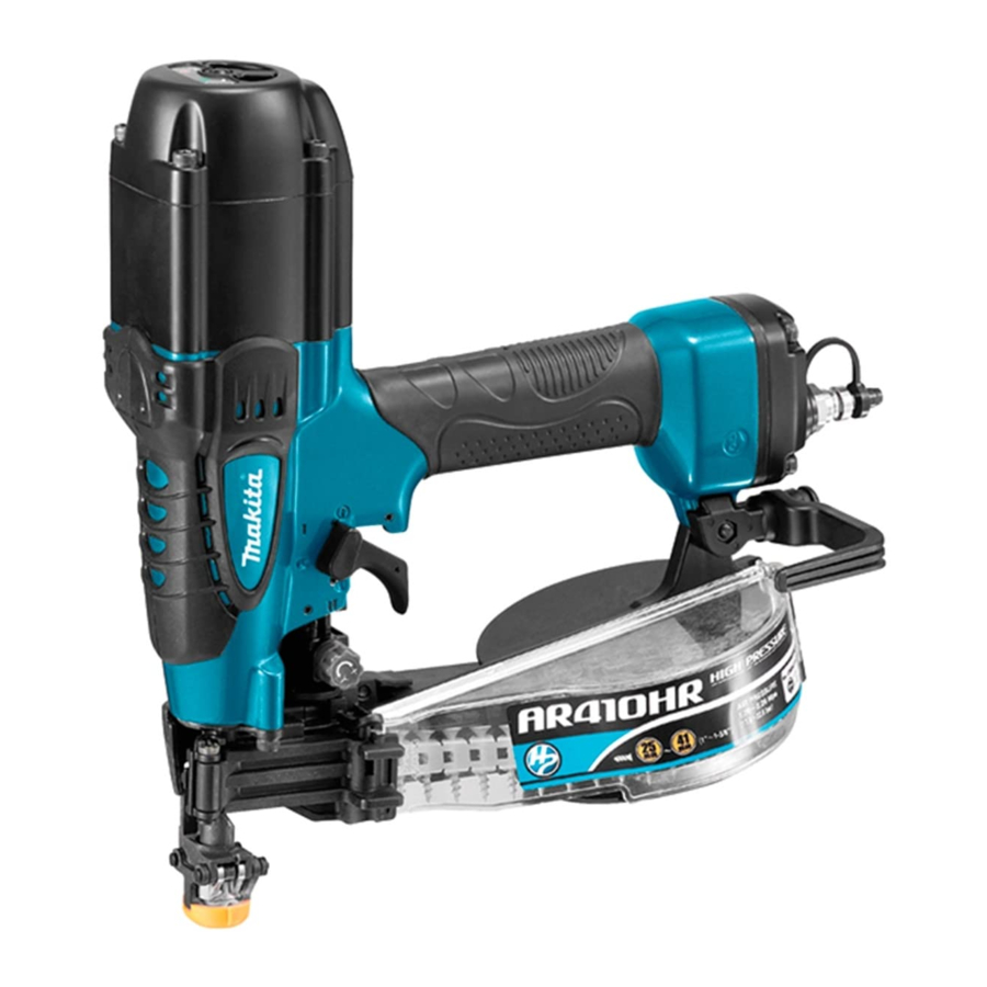
Makita AR410HR - Pneumatic Auto Feed Coil Screwdriver Manual
- Instruction manual (69 pages) ,
- Instruction manual (64 pages) ,
- Instruction manual (65 pages)
Advertisement
SPECIFICATIONS
| Model | AR410HR |
| Air pressure | 1.76 - 2.26 MPa (17.6 - 22.6 bar) |
| Screw length | Coil type 25 - 41 mm |
| Screw capacity | Sheet-collated - 100 pcs |
| Safety Device | Contact Arm System |
| Drive Adjustment | Dial Type (Adjustment Range: 6mm) |
| Screw Feed Mechanism | Feed Piston System |
| Min. hose diameter | 5.0 mm |
| Pneumatic tool oil | ISO VG32 or equivalent |
| Dimensions (L X H X W) | 296 mm X 116 mm X 305 mm |
| Net weight | 2.0 kg |
- Due to our continuing program of research and development, the specifications herein are subject to change without notice.
- Specifications may differ from country to country.
- Weight according to EPTA-Procedure 01/2003
Symbols
The following show the symbols used for the equipment. Be sure that you understand their meaning before use.
- Read instruction manual.
![]()
- Wear safety glasses.
![]()
- Do not use on scaffoldings, ladders.
![]()


Intended use
The tool is intended for the preliminary interior work such as fixing floor joists or common rafters and framing work in 2 "x 4" housing.
Noise
The typical A-weighted noise level determined according to EN792:
Sound pressure level (LpA): 81 dB(A)
Sound power level (LWA): 94 dB(A)
Uncertainty (K): 3 dB(A)
Wear ear protection
Vibration
The vibration total value determined according to EN792:
Vibration emission (ah): 2.5 m/s2 or less
Uncertainty (K): 1.5 m/s2
- The declared vibration emission value has been measured in accordance with the standard test method and may be used for comparing one tool with another.
- The declared vibration emission value may also be used in a preliminary assessment of exposure.

- The vibration emission during actual use of the power tool can differ from the declared emission value depending on the ways in which the tool is used.
- Be sure to identify safety measures to protect the operator that are based on an estimation of exposure in the actual conditions of use (taking account of all parts of the operating cycle such as the times when the tool is switched off and when it is running idle in addition to the trigger time).
Pneumatic nailer/stapler safety warnings
Read all safety warnings and all instructions. Failure to follow the warnings and instructions may result in serious injury, electric shock and/or fire.
Save all warnings and instructions for future reference.
For personal safety and proper operation and maintenance of the tool, read this instruction manual before using the tool.
General safety
- Do not permit those uninstructed to use the tool.
- No horseplay. Respect the tool as a working implement.
- Do not operate when under the influence of alcohol, drugs or the like.
- Never alter the tool.
Personal protective equipments
- Always wear safety glasses to protect your eyes from dust or fastener injury.
![]()
It is an employer's responsibility to enforce the use of safety eye protection equipment by the tool operators and by other persons in the immediate working area.
For Australia and New Zealand only
Always wear safety glasses and face shield to protect your eyes from dust or fastener injury. The safety glasses and the face shield should conform with the requirements of AS/NZS 1336.

- Wear hearing protection to protect your ears against exhaust noise and head protection. Also wear light but not loose clothing. Sleeves should be buttoned or rolled up. No necktie should be worn.

Work area safety
- Keep work area clean and well lit. Cluttered or dark areas invite accidents.
- Do not operate the tool in explosive atmospheres, such as in the presence of flammable liquids, gases or dust. Operating the tool can create sparks which may ignite the dust or fumes.
- Keep children and bystanders away while operating the tool. Distractions can cause you to lose control.
- Illuminate the work area sufficiently.
- There may be local regulations concerning noise which must be complied with by keeping noise levels within prescribed limits. In certain cases, shutters should be used to contain noise.
Safety devices
- Make sure all safety systems are in working order before operation. The tool must not operate if only the trigger is pulled or if only the contact arm is pressed against the wood. It must work only when both actions are performed. Test for possible faulty operation with fasteners unloaded and the pusher in fully pulled position.
- Do not play with the contact element: it prevents accidental discharge, so it must be kept on and not removed. Securing the trigger in the ON position is also very dangerous. Never attempt to fasten the trigger. Do not operate a tool if any portion of the tool operating controls is inoperable, disconnected, altered, or not working properly.
- Do not attempt to keep the contact element depressed with tape or wire. Death or serious injury may occur.
- Always check contact element as instructed in this manual. fasteners may be driven accidentally if the safety mechanism is not working correctly.
- When not operating the tool, always lock the trigger by turning the change lever to the LOCK position.
- Make sure that the trigger is locked when the change lever is set to the LOCK position.
Loading fasteners
- Do not load the tool with fasteners when any one of the operating controls is activated.
- Use only fasteners specified in this manual. The use of any other fasteners may cause malfunction of the tool.
Power source
- Never connect the tool to compressed air line where the air pressure can exceed the suitable air pressure range of the tool, specified in the "SPECIFICATIONS" table, by 10%. Make sure that the pressure supplied by the compressed air system does not exceed the suitable air pressure range of the tool. Set the air pressure initially to the lower value of the suitable air pressure range.
- Operate the tool at the lowest pressure required for the application, in order to prevent unnecessarily high noise levels, increased wear and resulting failures.
- Never use the tool with other than compressed air. If bottled gas (carbon dioxide, oxygen, nitrogen, hydrogen, air, etc.) or combustible gas (hydrogen, propane, acetylene, etc.) is used as a power source for this tool, the tool will explode and cause serious injury.
- Always disconnect the air hose and remove all of the fasteners:
- when unattended;
- before performing any maintenance or repair;
- before cleaning a jam;
- Before moving the tool to a new location.
- Use only pneumatic tool oil specified in this manual.
Operational safety
- Always check the tool for its overall condition and loose screws before operation. Tighten as required.
- Handle the tool carefully, as there is high pressure inside the tool that can be dangerous if a crack is caused by rough handling (dropping or striking). Do not attempt to carve or engrave on the tool.
- Stop the operation immediately if you notice something wrong or out of the ordinary with the tool. An improperly functioning tool must not be used.
- Do not point the ejection port at anyone in the vicinity. Keep hands and feet away from the ejection port area.
- Always assume that the tool contains fasteners.
- Never point the tool toward yourself or anyone whether it contains fasteners or not.
- Do not rush the job or force the tool. Handle the tool carefully.
- Do not activate the tool unless the tool is placed firmly against the workpiece.
- Never hold or carry the tool with a finger on the trigger or hand it to someone in this condition. Accidental firing can cause serious injury.
- Never use fastener driving tools marked with the symbol "Do not use on scaffoldings, ladders" for specific application for example:
- when changing one driving location to another involves the use of scaffoldings, stairs, ladders, or ladder alike constructions, e.g. roof laths;
- closing boxes or crates;
- fitting transportation safety systems e.g. on vehicles and wagons.
- Check walls, ceilings, floors, roofing and the like carefully to avoid possible electrical shock, gas leakage, explosions, etc. caused by striking live wires, conduits or gas pipes.
- Do not use the tool for fastening electrical cables. It is not designed for electric cable installation and may damage the insulation of electric cables thereby causing electric shock or fire hazards.
- Watch your footing and maintain your balance with the tool. Make sure there is no one below when working in high locations, and secure the air hose to prevent danger if there is sudden jerking or catching.
- On rooftops and other high locations, drive fasteners as you move forward. It is easy to lose your footing if you drive fasteners while inching backward. When driving fasteners against perpendicular surface, work from the top to the bottom. You can perform driving operations with less fatigue by doing so.
- A fastener will be bent or the tool can become jammed if you mistakenly drive fastener on top of another fastener or strike a knot in the wood. The fastener may be thrown and hit someone, or the tool itself can react dangerously. Place the fasteners with care.
- Do not leave the loaded tool or the air compressor under pressure for a long time out in the sun. Be sure that dust, sand, chips and foreign matter will not enter the tool in the place where you leave it setting.
- Never attempt to drive fasteners from both the inside and outside at the same time. Fasteners may rip through and/or fly off, presenting a grave danger.
Service
- Perform cleaning and maintenance right after finishing the job. Keep the tool in tip-top condition. Lubricate moving parts to prevent rusting and minimize friction-related wear. Wipe off all dust from the parts.
- Ask Makita authorized service center for periodical inspection of the tool.
- To maintain product SAFETY and RELIABILITY, maintenance and repairs should be performed by Makita Authorized Service Centers, always using Makita replacement parts.
SAVE THESE INSTRUCTIONS.
DO NOT let comfort or familiarity with product (gained from repeated use) replace strict adherence to safety rules for the subject product. MISUSE or failure to follow the safety rules stated in this instruction manual may cause serious personal injury.
INSTALLATION
Selecting air hose
Fig.1

Use a high pressure resistant air hose.
Use an air hose as large and as short as possible to assure continuous, efficient screw-driving operation.

- Low air output of the compressor, or a long or smaller diameter air hose in relation to the screwdriving frequency may cause a decrease in the driving capability of the tool.
Lubrication
Before and after use, oil the tool with pneumatic tool oil by placing two or three drops into the air fitting. For proper lubrication, the tool must be fired a couple of times after pneumatic tool oil is introduced.
Fig.2

FUNCTIONAL DESCRIPTION
- When adjusting driving depth, always lock the trigger and disconnect the air hose.
Adjuster (drive depth adjuster) Operating Method
Fig.3

- Deep
- Shallow
Fig.4

- Sunk too deeply (turn to raising side)
- Appropriate
- Raised too high (turn to sink side)
- When adjusting driving depth, always lock the trigger and disconnect the air hose.
This driver is equipped with an adjuster for adjusting screw driving depth.
Turn the adjuster to adjust driving depth. Driving adjustment range is 6mm. (one turn of adjuster adjusts depth by approximately 0.8mm.)
Hook
- When using the hook, or changing its position, always lock the trigger, and disconnect the air hose. Do not fasten hook onto waist belt, etc.
- If hook becomes unfastened and the driver drops, driver may operate by mistake, and lead to injury.
Fig.5

- Hook
- Screw
The hook is useful for hanging up the driver temporarily.
The mounting position of the hook on the driver can be changed.
Remove the hook mounting screw, change position of hook, and re-secure screw.
Switcher Mode Selection
Fig.6

- Knob
This driver is equipped with a switcher to enable selection of mode for optimum driving according to the material of the workpiece. Set to mode positions shown in "Switching Mode Chart" below for optimum use. Thoroughly turn the knob until it clicks to a halt properly at either position (1) or (2).If the driver is used with the switcher in a position between (1) and (2), driver components may become damaged, and/or normal performance not achieved.
| Steel sheet backing | Steel sheet thickness 0.8 mm | (2) | (2) | (2) | |
| Steel sheet thickness 0.6 mm | (1) | (1) | (1).(2) | ||
| Steel sheet thickness 0.6 mm | (1) | (1) | (1) | ||
| Wood backing | (1) | (1) | (1) | (1) | |
| Screw length | 25 mm | 28 mm | 32 mm | 41 mm | |
Suitable for use on general plasterboard with thicknesses of 9.5mm, 12.5mm and 15mm.
Steel sheet backing up to 0.8mm thick can be worked on (screws cannot be driven into layered steel sheet backing).
Always use Makita genuine linked screws.
We recommend that in normal situations the driver be used in Switching Mode (1), and set to Switching Mode (2) when screws cannot be driven for lack of power.
ASSEMBLY
Loading Screws
- Always disconnect air hose from main unit before loading screws.
- If the main unit is operated by mistake, it may lead to personal injury.
- Disconnect air hose.
- Press down lever while opening door.
Fig.7
![]()
- Lever
- Open magazine cap.
Fig.8
![]()
- Magazine cap
- Load screws into magazine.
- Pull out lead screw as far as driver guide and then close magazine cap.
- Completely load lead screw into screw channel. At this point, check to see that screw is completely set in feeding claw. At this time, if the screw cannot be set because the bit has come down as far as the driver guide, turn the main unit upside down (driver guide is on top), and return the bit to its designated position.
- Slowly close door until lever stops fully.
Fig.9
![]()
- Screw channel
- Lead screw
- Feeding claw


OPERATION
How to Drive Screws
- The utilized air pressure must be between 1.76 and 2.26MPa. Do not repeatedly drive screw(s) in on top of a screw that has been already driven in.
- This driver is not an impact gun, so it requires a reasonable amount of pressing.
- If the main unit is not pressed sufficiently, the screw may not drive in flush to workpiece, or come out.
- Always press the end of the discharge nose at a right angle onto the workpiece and then drive in screw. We recommend that you use the intermitent-drive action to ensure proper screw driving.
Fig.10, Fig.11

First, lightly press the end of the contact arm onto a workpiece.
Next, pull the trigger. Here, do not release the trigger until the motor stops running. Note that if the trigger is released too soon, the screw may not be driven in flush to workpiece, and/or the screw feed may be impaired.
Switching between intermitent drive and continuous drive
Intermitent Drive Method
Fig.12

- Lever
Fig.13

Intermitent drive is where the contact arm is pressed against a workpiece, and the trigger pulled to drive in one screw.
Set the switching lever to the ![]() position to set driver to "Intermitent Drive Mode".
position to set driver to "Intermitent Drive Mode".
- Press contact arm against workpiece.
- Pull trigger.
Continuous Drive Method
Fig.14

- Lever
Fig.15

Continuous drive is where the contact arm is repeatedly pressed onto different areas of workpiece while the trigger is held down to continuously drive in screws.
Set the switching lever to the ![]() position to set driver to "Continuous Drive Mode".
position to set driver to "Continuous Drive Mode".
- Pull trigger.
- With the trigger held down, each time the contact arm is pressed against the workpiece, a screw will be driven in continuously.
Trigger Locking Method
This driver has a trigger lock to prevent accidents due to mistaken operation when main unit is not being used. The trigger lock is a mechanism that locks the trigger, preventing discharge of screws.
Set the switching lever to the ![]() position to set driver to "Trigger Lock".
position to set driver to "Trigger Lock".
When drive screws, set lock lever to the ![]() position or
position or ![]() position. When not using the driver, always lock the trigger and disconnect the air hose.
position. When not using the driver, always lock the trigger and disconnect the air hose.
How to Cut linked Sheet
Fig.16

- When cutting linked sheet, always lock trigger, and disconnect air hose.
When using linked screws, the linked sheet protrudes from the driver guide. Tear away the protruding linked sheet in the direction of the arrow.
MAINTENANCE
- Always disconnect the air hose from the tool before attempting to perform inspection or maintenance.
- Never use gasoline, benzine, thinner, alcohol or the like. Discoloration, deformation or cracks may result.
How to Rectify Screw Jam
- When rectifying screw jam, always lock trigger, and disconnect air hose.
Fig.17

- Hammer
- Bar
Lock trigger and disconnect air hose.
Open door, and pull out linked screws.
Insert thin metal bar into discharge nose, and hit it with a hammer. In some cases, this metal bar will become stuck when hit. Note, that at such times, the bit must not be hit, as the bit end may be damaged, and lead to impaired screw driving.
Fig.18

- Screw
- Screwdriver
Remove screw(s) jammed inside driver guide using minus screwdriver or other such tool.
After removing screw(s), make sure bit is not protruding into screw channel (if it is, press it out of the way using the metal bar).
After removing the jammed screw(s), reload the driver with screws.
How to Replace Bit
- When replacing bit, always lock trigger, disconnect air hose, and remove all loaded screws.
Take care not to lose small components.
Replace bit in clean surroundings to prevent dust and dirt from getting onto internal components.
Removing Bit
Fig.19

- Hex bolt
- Hex wrench
- Top cap
- Top cap gasket
- Top cap spacer
- Disconnect hose and remove all loaded screws.
- Use hex wrench to loosen the four hex bolts, and then remove top cap.
- The top cap spacer is removable, but please leave it on the driver.
- If top cap gasket is removed with top cap, be careful not to misshapen it, and be sure to put it back when reassembling.
- Insert the hex wrench into the bit channel of the driver guide, and push out the piston assembly.
Fig.20
![]()
- Piston assembly
- Hex wrench
- Driver guide
- Use an eyeleteer, etc., to remove rubber ring (white) from unloaded piston assembly.
- As the new bit comes with a white rubber ring, the old one can be cut out with a cutter knife, etc. if it is difficult to remove.
- Fig.21
![]()
- Eyeleteer
- Rubber ring (white)
- Piston assembly
- Fig.22
![]()
- Cutter knife
- Rubber ring (white)
- Piston assembly
- Next, extract pin from piston assembly.
Fig.23
![]()
- Pin
- Piston assembly
- Lower the piston, and then remove the piston cap and driver bit.
Fig.24
![]()
- Piston cap
- Driver bit
- Piston


Mounting Bit
- Mount new driver bit onto piston.
Fig.25
![]()
- New driver bit
- Piston
- Next, mount piston cap onto piston assembly. At this point, make sure that piston assembly and piston cap holes are aligned.
Fig.26
![]()
- Hollowed side
- Piston cap
- Piston assembly
- Holes
- Mount piston cap with hollowed side up as per diagram.
- Pass pin through piston assembly.
Fig.27
![]()
- Pin
- Piston assembly
- Mount rubber ring onto piston assembly.
Fig.28
![]()
- Rubber ring
- Piston assembly
- Align the bit shape with the shape of driver's bit channel and then insert bit.
Fig.29
![]()
- Mount top cap onto driver and insert four hex bolts into holes.
Fig.30
![]()
- Hex bolt
- Top cap
- Firmly tighten hex bolts using hex wrench. At this point, tighten in order [(1) to (4)] shown by arrows.
Fig.31
![]()
- Hex bolt
- Hex wrench
- Prescribed tightening torque is between 7.5 and 8.5N•m


After completing bit replacement, fully check to see that there are no abnormalities, and then commence driving screws.
Drain tool
Remove the hose from the tool. Place the tool so that the air fitting faces down to the floor. Drain as much as possible.
Cleaning of tool
Iron dust that adhere to the magnet can be blown off by using an air duster.
Cap
When not in use, disconnect the hose. Then cap the air fitting with the cap.
Fig.32

Storage
When not in use, the tool should be stored in a warm and dry place.
Maintenance of compressor and air hose
Fig.33

- Drain cock
After operation, always drain the compressor tank. If moisture is allowed to enter the tool, It may result in poor performance and possible tool failure.
Keep the air hose away from heat (over 60°C, over 140°F), away from chemicals (thinner, strong acids or alkalis). Also, route the hose away from obstacles which it may become dangerously caught on during operation. Hoses must also be directed away from sharp edges and areas which may lead to damage or abrasion to the hose.

To maintain product SAFETY and RELIABILITY, repairs, any other maintenance or adjustment should be performed by Makita Authorized Service Centers, always using Makita replacement parts.
OPTIONAL ACCESSORIES
- These accessories or attachments are recommended for use with your Makita tool specified in this manual. The use of any other accessories or attachments might present a risk of injury to persons. Only use accessory or attachment for its stated purpose.
If you need any assistance for more details regarding these accessories, ask your local Makita Service Center.
- Air hoses
- Safety goggles
NOTE:
- Some items in the list may be included in the tool package as standard accessories. They may differ from country to country.

Documents / ResourcesDownload manual
Here you can download full pdf version of manual, it may contain additional safety instructions, warranty information, FCC rules, etc.
Download Makita AR410HR - Pneumatic Auto Feed Coil Screwdriver Manual
Advertisement
Thank you! Your question has been received!


Need Assistance?
Do you have a question about the AR410HR that isn't answered in the manual? Leave your question here.