Black & Decker BDL190S - BULLSEYE Auto Leveling Laser / Wood & Metal Stud / AC Wire Sensor Manual
- Instruction manual (6 pages) ,
- Instruction manual (6 pages) ,
- Instruction manual (2 pages)
Advertisement
Safety Instructions
- Do not operate the laser in explosive atmospheres, such as in the presence of flammable liquids, gases, or dust.
- Use the laser only with the specifically designated batteries. Use of any other batteries may create a risk of fire.
- Store idle laser out of reach of children and other untrained persons. Lasers are dangerous in the hands of untrained users.
- Use only accessories that are recommended by the manufacturer for your model. Accessories that may be suitable for one laser, may create a risk of injury when used on another laser.
- Do not use optical tools such as a telescope or transit to view the laser beam. Serious eye injury could result.
- Do not place the laser in a position which may cause anyone to intentionally or unintentionally stare into the laser beam. Serious eye injury could result
- Turn the laser off when it is not in use. Leaving the laser on increases the risk of staring into the laser beam.
- Repairs and servicing MUST be performed by a qualified repair facility. Repairs performed by unqualified personnel could result in serious injury.
![]()
DO NOT DISASSEMBLE THE LASER. There are no user serviceable parts inside. Disassembling the Laser will void all warranties on the product. Do not modify the product in any way. Modifying the tool may result in Hazardous Laser Radiation Exposure.- Do not operate the laser around children or allow children to operate the laser. Serious eye injury may result.
- Do not remove or deface warning labels. Removing labels increases the risk of exposure to radiation.
- Position the laser securely. Damage to the laser or serious injury could result if the laser falls.
![]()
Occasionally, pipes and electrical wiring may not be detected by this product. The sensor will not detect hot wires inside metal pipe or metal conduit, behind metallic wall covering, or behind some plywood or other dense materials.![]()
Material thickness, type of material, moisture content, and other variables can affect sensing results. The sensor may detect electric wiring or pipes in the same manner that studs are detected depending on their location to the wall surface. Use caution when drilling, nailing or cutting into walls, floors and ceilings which may contain electrical wiring or pipes. These items may be detected by the sensor in the same manner in which studs are detected. Because studs are normally spaced 16 inches (406 mm) or 24 inches (610 mm) apart and are usually 1-1/2 inches (38 mm) wide, beware of anything closer together or of a different width. Always turn off the power when working near electrical wires.![]()
Use of controls or adjustments or performance of procedures other than those specified in this manual may result in hazardous laser radiation exposure.- This product is intended for use in a temperature range of 50°F(10°C) - 104°F(40°C).

Liquid Crystal Display (First Aid Measures)
- If liquid crystal comes in contact with your skin:
Wash area off completely with plenty of water. Remove contaminated clothing. - If liquid crystal gets into your eye:
Flush the affected eye with clean water and then seek medical attention. - If liquid crystal is swallowed:
Flush your mouth thoroughly with water. Drink large quantities of water and induce vomiting. Then seek medical attention.
The label on your tool may include the following symbols.
| V | volts |
| nm | wavelength in nanometers |
 | AC Wire Warning |
| mW | milliwatts |
| llla | Class llla Laser |
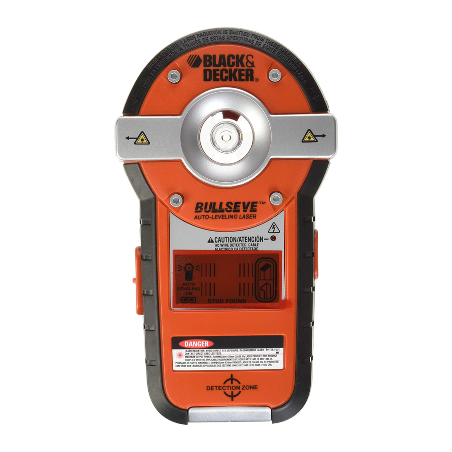
FEATURES

- Laser On/Off Button
- Detector On/Off Button
- AC Wire Indicator LED
- LCD Screen
- Wall Attachment - Hanging Cone (keyhole)
- Wall Attachment - Drywall Pin
- Self-Leveling Laser Lines
- Battery Compartment Cover (back side of unit)
For your convenience and safety, the following labels are on your laser.

Installing the Battery
Ensure laser on/off switch (A) is in the full off position by moving laser button to "O" position. Remove the battery compartment cover (H). Insert 2 fresh 1.5 volt AA alkaline batteries making sure to match (+) and (-) terminals correctly. Replace battery compartment cover.

Batteries can explode, or leak, and can cause injury or fire. To reduce this risk:
- Carefully follow all instructions and warnings on the battery label and package.
- Always insert batteries correctly with regard to polarity (+ and -), marked on the battery and the equipment.
- Do not short battery terminals.
- Do not charge batteries.
- Do not mix old and new batteries. Replace all of them at the same time with new batteries of the same brand and type.
- Remove dead batteries immediately and dispose of per local codes.
- Do not dispose of batteries in fire.
- Keep batteries out of reach of children.
- Remove batteries if the device will not be used for several months.
"Transporting batteries can possibly cause fires if the battery terminals inadvertently come in contact with conductive materials such as keys, coins, hand tools and the like. The US Department of Transportation Hazardous Material Regulations (HMR) actually prohibit transporting batteries in commerce or on airplanes (i.e. packed in suitcases and carryon luggage) UNLESS they are properly protected from short circuits. So when transporting individual batteries, make sure that the battery terminals are protected and well insulated from materials that could contact them and cause a short circuit."
LOW BATTERY INDICATOR
A battery energy level indicator is displayed in the lower left hand corner of the display screen.
Operating Instructions
NOTE: Detecting elements for wood and metal studs and AC Wires are located in the lower part of the unit.

STUD DETECTION
For stud detection through up to 3/4 inch (19mm) thick drywall.
- Hold unit straight up and down and place flat against wall as shown in Figure 1.
![]()
- Press in and hold the detector on/off button (B). LCD screen (D) will light and detector will run initialization process.
- READY message will appear on LCD screen and the unit will beep once to indicate it is calibrated and ready for detection.
- Slide unit slowly, Figure 2, horizontally across surface of wall without lifting or tilting. When the STUD FOUND message appears on the LCD screen, slow down and keep sliding until EDGE message appears and beep sounds as shown in Figure 3. This is the stud edge. Mark this spot (at arrow on lower part of unit).

- Keep moving past mark until EDGE and STUD FOUND disappear.
- Continue holding detector button and reverse direction.
- Find and mark other stud edge, following step 4.
- Center of the stud is between marks.


AC WIRE SENSING
Test on a known "live" AC wire before each use. For AC Detection up to 1-1/2 inches (38mm) from the surface. The sensor detects AC voltage and will identify only live wires. AC voltage detection feature works continuously when detecting studs. It assists in identifying when the sensor is near live AC wiring and detector button (B) is depressed. Once AC voltage has been detected AC wire indicator LED (C) will light.
If the unit is calibrated close to AC wire, it may decrease AC wiring sensor sensitivity. Static charge may spread detection 12 inches (30.4cm) on both sides of wire.
Occasionally, pipes and electrical wiring may not be detected by this product. Observe caution when cutting or drilling into areas that may contain concealed pipes or wiring. The sensor will not detect live wires inside metal pipe or metal conduit, behind metallic wall covering, or behind some plywood or other dense materials.
Use caution if area has plywood, thick wood backing behind drywall, or thicker than normal walls.

Always turn off the power when working near electrical wires, electric shock may result.
AUTO LEVELING LASER LINES
Operation of Laser: Place unit flat against wall as shown in Figure 1. Move laser on/off AUTO LEVELING LASER LINES button (A) to "I" position to actuate the auto leveling horizontal laser lines.
HANGING ON DRYWALL SURFACES ONLY
Hands Free Operation of Laser: To hang the unit on a wall, remove the orange protective cap from the drywall pin (F) and store it on the cone as shown in Figure 4. Push pin into drywall (Figure 5). When pressing pin into drywall, make sure it is straight and seated firmly. Hang the laser on the cone as shown in Figure 6 and check to make sure that the unit is secure on the wall. Figure 7 illustrates a typical application for the laser when it is wall mounted.


Pin is sharp and should be handled with care. The drywall pin should always be pushed in by hand and never driven by a hammer. Replace protective cap after each use.
NOTE: The pin is only for use on drywall NOT other surfaces including plaster.
HANGING ON OTHER SURFACES
Hands Free Operation of Laser: For surfaces other than drywall, the (key hole) hanging cone (E) can be used with a standard nail or screw in a predrilled hole. To use the keyhole hanging cone, place it over a nail or screw on a vertical surface with the narrow portion of the opening pointing upward. Push the laser onto the hanging cone until it snaps into place. To remove the laser, lift it slightly and pull it straight off. The unit can also be used with the hanging cone attached to the back and then hanging the unit on the nail or screw. Make sure it is straight and seated firmly on the cone and that the unit is secure on the wall.

Laser Radiation, avoid direct eye exposure.
Helpful Hints
- If the laser light becomes dim or is no longer visible when the switch is in the on position check or change the battery.
- The laser lines are only level on the wall against which the unit is held or hung. The short line visible on any adjacent wall is not level.
- The laser unit is a wall use tool only and only generates level lines when held against a vertical surface.
- The laser unit is equipped with a pendulum lock that stops pendulum motion when the laser on/off switch is moved to the off position.
- If the laser on/off switch is pushed part way to the on position, the laser lines may be on while the pendulum lock is still engaged.
- Hold stud sensor straight up and down.
Helpful Hints (Con't)
- Because studs are normally spaced 16 inches or 24 inches apart and are 1-1/2 inches wide, beware of anything closer together or of a different width. Doors and windows are constructed with studs and headers which are closer together.
- When using unit over a stucco wall, place a piece of cardboard over the surface to help provide a smooth motion across the wall.
- Avoid materials which have inconsistent density such as:
- Carpeting and padding
- Ceramic floor tile
- Wallpaper containing metallic foils or fibers. Generally, surfaces covered with regular wallpaper or fabric will scan with no difference in function.
- Walls that are freshly painted and are still damp.
- Excessively thick plaster and lath.
TROUBLESHOOTING
| Problem | Possible Cause | Solution |
|
|
|
|
|
|
|
|
|
|
|
|
|
| |
|
|
|
Always turn off the power when working near electrical wires.
Storage
Always store this product indoors and in its protective case.
Maintenance
Use only mild soap and damp cloth to clean the tool. Never let any liquid get inside the tool; never immerse any part of the tool into a liquid.

To assure product SAFETY and RELIABILITY, repairs, maintenance and adjustment (other than those listed in this manual) should be performed by authorized service centers or other qualified service organizations, always using identical replacement parts.
Accessories
Recommended accessories for use with your tool are available from your local dealer or authorized service center. If you need assistance regarding accessories, please call: 1-800-544-6986.
The use of any accessory not recommended for use with this tool could be hazardous.
SERVICE INFORMATION
All Black & Decker Service Centers are staffed with trained personnel to provide customers with efficient and reliable power tool service. Whether you need technical advice, repair, or genuine factory replacement parts, contact the Black & Decker location nearest you. To find your local service location, refer to the yellow page directory under "Tools—Electric" or call: 1- 800-544-6986 or visit www.blackanddecker.com
TECHNICAL SPECIFICATIONS OF LASER LEVEL:
| Laser Diode Wavelength: | 650 ± 5 nm (red color) |
| Laser Class: | Class IIIa |
| Working Range: | Up to 20 feet (depends on light conditions) |
| Leveling Accuracy: | ±1/8 inch (3 mm) @ 10 feet (3 m) |
| Auto Leveling Range: | ±4.5° |
| Auto Leveling Lines Settling Time: | <5 sec |
| Batteries: | 2 AA Alkaline (included) |
| Voltage: | 3 Volt |
| Operating Temperature: | 50°F (10°C)- 104°F (40°C) |
Imported by
Black & Decker (U.S.) Inc.,
701 E. Joppa Rd.
Towson, MD 21286 U.S.A.
BlackandDecker.com
1-800-544-6986
If you have a question or experience a problem with your Black & Decker purchase, go to
HTTP://WWW.BLACKANDDECKER.COM/INSTANTANSWERS for instant answers 24 hours a day.
If you can't find the answer or do not have access to the internet, call 1-800-544-6986 from 8 a.m. to 5 p.m. EST Mon. - Fri. to speak with an agent. Please have the catalog number available when you call.

Documents / Resources
References
Download manual
Here you can download full pdf version of manual, it may contain additional safety instructions, warranty information, FCC rules, etc.
Advertisement
Thank you! Your question has been received!


Need Assistance?
Do you have a question about the BDL190S that isn't answered in the manual? Leave your question here.