Table of Contents
Advertisement
Available languages
Available languages
Quick Links
Operator's Manual
210 AMP
MIG WELDER
Model No. 117.205710
CAUTION:
Before using welder, read this
manual and follow all its Safety
Rules and Operating Instructions.
Sears, Roebuck and Co., Hoffman Estates, IL 60179 U.S.A.
Visit the Craftsman web page: www.sears.com/craftsman
OM-194 199E
April 2001
w
Safety Rules
w
Installation
w
Operation
w
Maintenance
w
Parts
w
Español
Advertisement
Chapters
Table of Contents
Troubleshooting

Related Manuals for Craftsman 117.205710


Summary of Contents for Craftsman 117.205710
- Page 1 Model No. 117.205710 CAUTION: Before using welder, read this manual and follow all its Safety Rules and Operating Instructions. Sears, Roebuck and Co., Hoffman Estates, IL 60179 U.S.A. Visit the Craftsman web page: www.sears.com/craftsman OM-194 199E April 2001 Safety Rules Installation Operation...
- Page 2 Effective January 1, 2000 Full One Year Warranty for Craftsman Welding Gun or Cables. For one year from the date of purchase, when the welding gun or cables are operated and maintained according to the owner’s manual instructions, if the welding gun or cables fail due to a defect in material or workmanship, Sears will repair or replace the welding gun or cables free of charge.
-
Page 3: Table Of Contents
WARRANTY SECTION 1 – SAFETY PRECAUTIONS - READ BEFORE USING 1-1. Symbol Usage 1-2. Arc Welding Hazards The following terms are 1-3. Additional Symbols for Installation, Operation, and Maintenance used interchangeably 1-4. Principal Safety Standards throughout this manual: 1-5. EMF Information MIG = GMAW SECTION 2 –... -
Page 4: Section 1 – Safety Precautions - Read Before Using
SECTION 1 – SAFETY PRECAUTIONS - READ BEFORE USING 1-1. Symbol Usage Means Warning! Watch Out! There are possible hazards with this procedure! The possible hazards are shown in the adjoining symbols. Y Marks a special safety message. Means “Note”; not safety related. 1-2. - Page 5 D Do not use welder to thaw frozen pipes. D Remove stick electrode from holder or cut off welding wire at contact tip when not in use.
-
Page 6: Additional Symbols For Installation, Operation, And Maintenance
1-3. Additional Symbols For Installation, Operation, And Maintenance FIRE OR EXPLOSION hazard. D Do not install or place unit on, over, or near combustible surfaces. D Do not install unit near flammables. D Do not overload building wiring – be sure power supply system is properly sized, rated, and protected to handle this unit. -
Page 7: Emf Information
1-5. EMF Information Considerations About Welding And The Effects Of Low Frequency Electric And Magnetic Fields Welding current, as it flows through welding cables, will cause electro- magnetic fields. There has been and still is some concern about such fields. However, after examining more than 500 studies spanning 17 years of research, a special blue ribbon committee of the National Research Council concluded that: “The body of evidence, in the committee’... -
Page 8: Section 2 - Installation
SECTION 2 – INSTALLATION 2-1. Specifications Rated Welding Amperage Output Range 150 A @ 23 Volts 30 – 185 DC, 60% Duty Cycle Wire Type And Diameter Solid Steel / Stainless Flux Cored Aluminum Steel .030 – .045 in .030 – .035 in .023 –... -
Page 9: Welding Power Source Duty Cycle And Overheating
2-3. Welding Power Source Duty Cycle And Overheating 6 Minutes Welding Overheating 2-4. Welding Gun Duty Cycle And Overheating CAUTION WELDING LONGER THAN RATED DUTY CYCLE can damage gun and void warranty. Do not weld at rated load longer than shown below. Using gasless flux cored wire reduces gun duty cycle. -
Page 10: Installing Work Clamp
2-5. Installing Work Clamp 2-6. Installing Gas Supply Tools Needed: 5/8, 1-1/8 in OM-194 199 Page 7 Tools Needed: 1/2, 3/4 in Argon Gas Work Cable Boot Slide boot onto work cable. Route cable out front panel opening from inside. Negative (–) Output Terminal Connect cable to terminal and cover connection with boot. -
Page 11: Installing Welding Gun
2-7. Installing Welding Gun 2-8. Setting Gun Polarity Tools Needed: 3/4, 11/16 in Drive Assembly Gun Securing Knob Gun End Loosen securing knob. Insert gun end through opening until it bottoms against drive assembly. Tighten nut. Gun Trigger Plug Insert plug into receptacle, and tighten threaded collar. -
Page 12: Installing Wire Spool And Adjusting Hub Tension
2-9. Installing Wire Spool And Adjusting Hub Tension Tools Needed: 15/16 in 2-10. Changing Input Voltage Tools Needed: 3/8, 7/16 in OM-194 199 Page 9 Use compression spring with 8 in (200 mm) spools. When a slight force is needed to turn spool, tension is set. -
Page 13: Electrical Service Guide
2-11. Electrical Service Guide Input Voltage Input Amperes At Rated Output Max Recommended Standard Fuse Or Circuit Breaker Rating In Amperes Min Input Conductor Size In AWG/Kcmil Max Recommended Input Conductor Length In Feet (Meters) Min Grounding Conductor Size In AWG/Kcmil Reference: 1999 National Electrical Code (NEC) 1 Choose a circuit breaker with time-current curves comparable to a Time Delay Fuse. -
Page 14: Threading Welding Wire
2-13. Threading Welding Wire Open pressure assembly. Close and tighten pressure assembly, and let go of wire. Press gun trigger until wire comes out of gun. Reinstall contact tip and nozzle. OM-194 199 Page 11 Tools Needed: 6 in (150 mm) Pull and hold wire;... -
Page 15: Weld Parameter
2-14. Weld Parameter Wire Type, Wire Operator Shielding Gas, Diameter Controls And Flow Rate (inch) Voltage Tap .023 Wire Speed Voltage Tap E70S-6 .030 20 cfh+ Wire Speed Voltage Tap .035 Wire Speed Voltage Tap .023 Wire Speed E70S-6 Voltage Tap 75% Argon 75% Argon .030... -
Page 16: Aluminum Weld Parameter For Use With Optional Spool Gun
2-15. Aluminum Weld Parameter For Use With Optional Spool Gun Wire Type, Wire Type, Wire Wire Operator Shielding Gas, Diameter Controls And Flow Rate (inch) Voltage Tap .030 Wire Speed 4043 AL 4043 AL 100% Argon Voltage Tap .035 Wire Speed Voltage Tap .030 Wire Speed... -
Page 17: Section 3 - Operation
SECTION 3 – OPERATION 3-1. Front Panel Controls Controls For Standard Units Wire Speed Control Use control to select a wire feed speed. Scale around control is not actual wire feed speed, but is for reference only. Voltage Switch The higher the selected number, the thicker the material that can be welded (see Section 2-14). -
Page 18: Section 4 - Maintenance & Troubleshooting
SECTION 4 – MAINTENANCE & TROUBLESHOOTING 4-1. Routine Maintenance Replace Damaged Or Unreadable Labels Vacuum Inside 4-2. Circuit Breakers CB1 And CB2 4-3. Changing Drive Roll And Inlet Wire Guide Tools Needed: OM-194 199 Page 15 Y Disconnect power before maintaining. 3 Months 6 Months Blow Out Or... -
Page 19: Cleaning Or Replacing Gun Liner
4-4. Cleaning Or Replacing Gun Liner 3/8 in Lay gun cable out straight before installing new liner. Y Disconnect gun first. Head Tube Remove nozzle, contact tip, and adapter. Blow out gun casing. Tools Needed: 3/8 in Remove liner. To Reassemble Gun: Insert new liner. -
Page 20: Replacing Switch And/Or Head Tube
4-5. Replacing Switch And/Or Head Tube Remove handle locking nut. Secure head tube in vice. Install existing shock washer onto new head tube. Hand-tighten head tube into connector cable. Tools Needed: 3/4 in OM-194 199 Page 17 Y Disconnect gun first. Remove switch housing. -
Page 21: Replacing Gun Contact Tip
4-6. Replacing Gun Contact Tip Tools Needed: 4-7. Troubleshooting Welding Trouble No weld output; wire does not feed. Secure power cord plug in receptacle (see Section 2-12). Check and replace power switch if necessary. Check circuit breakers CB1 and/or CB2, and reset if necessary (see Section 4-2). Replace building line fuse or reset circuit breaker if open (see Section 2-12). -
Page 22: Section 5 - Electrical Diagram
SECTION 5 – ELECTRICAL DIAGRAM SB-186 065 Figure 5-1. Circuit Diagram OM-194 199 Page 19... -
Page 23: Section 6 - Mig Welding (Gmaw) Guidelines
SECTION 6 – MIG WELDING (GMAW) GUIDELINES 6-1. Typical MIG Process Connections Y Weld current can damage electronic parts in vehicles. Disconnect both battery cables before welding on a vehicle. Place work clamp as close to the weld as possible. Regulator/ Flowmeter Wire Feeder/... -
Page 24: Typical Mig Process Control Settings
6-2. Typical MIG Process Control Settings NOTE These settings are guidelines only. Material and wire type, joint design, fitup, position, shielding gas, etc. affect settings. Test welds to be sure they comply to specifications. Material thickness determines weld parameters. .035 in Wire Recommendation Size... -
Page 25: Holding And Positioning Welding Gun
6-3. Holding And Positioning Welding Gun NOTE Welding wire is energized when gun trigger is pressed. Before lowering helmet and pressing trigger, be sure wire is no more than 1/2 in (13 mm) past end of nozzle, and tip of wire is positioned correctly on seam. End View Of Work Angle End View Of Work Angle 0 -15... -
Page 26: Conditions That Affect Weld Bead Shape
6-4. Conditions That Affect Weld Bead Shape NOTE Weld bead shape depends on gun angle, direction of travel, electrode extension (stickout), travel speed, thickness of base metal, wire feed speed (weld current), and voltage. Short FILLET WELD ELECTRODE EXTENSIONS (STICKOUT) Slow OM-194 199 Page 23 Push... -
Page 27: Gun Movement During Welding
6-5. Gun Movement During Welding NOTE Normally, a single stringer bead is satisfactory for most narrow groove weld joints; however, for wide groove weld joints or bridging across gaps, a weave bead or multiple stringer beads works better. 6-6. Poor Weld Bead Characteristics 6-7. -
Page 28: Troubleshooting - Excessive Spatter
6-8. Troubleshooting – Excessive Spatter Possible Causes Wire feed speed too high. Voltage too high. Electrode extension (stickout) too long. Workpiece dirty. Insufficient shielding gas at welding arc. Dirty welding wire. 6-9. Troubleshooting – Porosity Possible Causes Insufficient shielding gas at welding arc. Wrong gas. -
Page 29: Troubleshooting - Lack Of Penetration
6-11. Troubleshooting – Lack Of Penetration Lack of Penetration Good Penetration Possible Causes Improper joint preparation. Improper weld technique. Insufficient heat input. 6-12. Troubleshooting – Incomplete Fusion Possible Causes Workpiece dirty. Insufficient heat input. Improper welding technique. 6-13. Troubleshooting – Burn-Through Possible Causes Excessive heat input. -
Page 30: Troubleshooting - Waviness Of Bead
6-14. Troubleshooting – Waviness Of Bead Possible Causes Welding wire extends too far out of nozzle. Unsteady hand. 6-15. Troubleshooting – Distortion Base metal moves in the direction of the weld bead. Possible Causes Excessive heat input. OM-194 199 Page 27 Waviness Of Bead –... -
Page 31: Common Mig Shielding Gases
6-16. Common MIG Shielding Gases This is a general chart for common gases and where they are used. Many different combinations (mixtures) of shielding gases have been developed over the years. The most commonly used shielding gases are listed in the following table. -
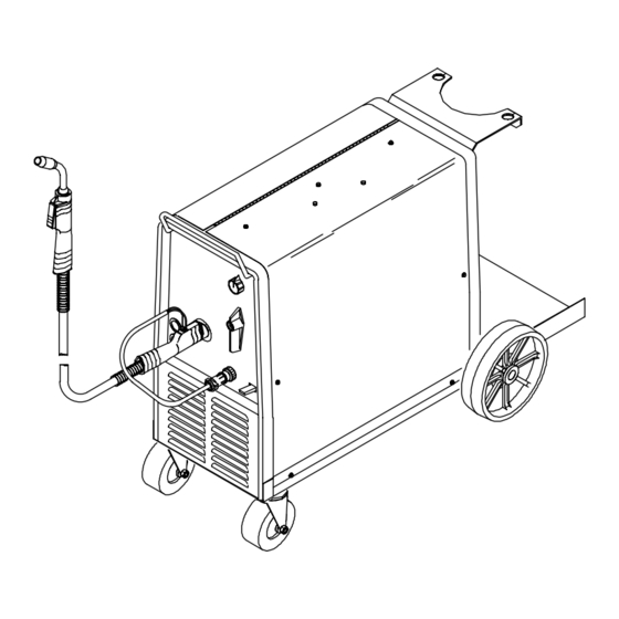
Page 32: Section 7 – Parts List
SECTION 7 – PARTS LIST–Welder Model No. 117.205710 * Standard hardware item – may be purchased locally. 801 572-C Figure 7-1. Main Assembly OM-194 199 Page 29... - Page 33 Parts List–Welder Model No. 117.205710 Item Dia. Part Mkgs....089 899 ....
- Page 34 Parts List–Welder Model No. 117.205710 * Standard hardware item – may be purchased locally. Fig.7–4 – 28 Item Dia. Part Mkgs....058 427 . . .
- Page 35 Parts List–Welder Model No. 117.205710 Item Dia. Part Mkgs. Figure 7-2. Baffle, Center w/Components (Continued) (Fig 7-1 Item 4) ....083 147 ..
- Page 36 Parts List–Welder Model No. 117.205710 To maintain the factory original performance of your equipment, use only Manufacturer’s Suggested Replacement Parts. Model number required when ordering parts from a Sears Parts /Repair Center. Item Part 169 589 Figure 7-3. M-15 Gun (Fig 7-1 Item 36) .
- Page 37 Parts List–Welder Model No. 117.205710 Item Part ....196 237 ....
- Page 38 Notes OM-194 199 Page 35...
- Page 39 Efectiva 1 enero, 2000 Garantía de un año para las antorchas o cables Craftsman. Por todo un año a partir de la fecha de compra, cuando se ha operado y se ha mantenido la antorcha y los cables de acuerdo a las instrucciones del manual del operador. Si la antorcha o los cables fallan debido a un defecto en material o mano de obra, Sears reparará...
- Page 40 GARANTIA SECCION 8 – PRECAUCIONES DE SEGURIDAD – LEA ANTES DE USAR 8-1. Uso de Símbolos ............. 8-2.
-
Page 41: Seccion 8 - Precauciones De Seguridad - Lea Antes De Usar
SECCION 8 – PRECAUCIONES DE SEGURIDAD – LEA ANTES DE USAR 8-1. Uso de Símbolos Significa ¡Precaución! ¡Cuidado! ¡Hay peligros posibles con este procedimiento! Los peligros posibles se mues- tra en los símbolos anexos. Y Anota un mensaje especial de seguridad. Significa NOTESE;... - Page 42 LOS RAYOS DEL ARCO pueden que- mar sus ojos y piel Los rayos del arco de un proceso de suelda produ- cen un calor intenso y rayos ultravioletas fuertes que pueden quemar los ojos y la piel. Las chispas se es- capan de la soldadura.
-
Page 43: Símbolos Adicionales Para Instalación, Operación Y Mantenimiento
8-3. Símbolos Adicionales para Instalación, Operación y Mantenimiento Peligro de FUEGO O EXPLOSION D No ponga la unidad encima de, sobre o cerca de superficies combustibles. D No instale la unidad cerca a objetos flamables. D No sobrecarga a los alambres de su edificio – asegure que su sistema de abastecimiento de potencia es adecuado en tamaño capacidad y protegido para cumplir con las necesidades de esta unidad. -
Page 44: Información Del Emf
8-5. Información del EMF Consideración acerca de Soldadura y los Efectos de Campos Eléctri- cos y Magnéticos de Baja Frecuencia La corriente de soldadura cuando fluye por los cables de soldadura causará campos electromagnéticos. Ha habido una precupación acer- ca de estos campos. Sin embargo, después de examinar más de 500 estudios sobre el transcurso de 17 años, un comité... -
Page 45: Seccion 9 - Instalacion
SECCION 9 – INSTALACION 9-1. Especificaciones Salida Nominal Gama de de Soldadura Amperaje 150 Amps @ 23 VDC, 60% Ciclo de 30 – 185 Trabajo Tipo de Alambre y Diámetro Sólido/ Tubular Inoxidable ,030 – ,045 pulg ,023 – ,035 pulg (0,8 –... -
Page 46: Ciclo De Trabajo De La Fuente De Poder De Soldadura Y El Sobrecalentamiento
9-3. Ciclo de trabajo de la Fuente de Poder de Soldadura y el sobrecalentamiento 6 Minutos Soldando Sobrecalentando 9-4. Ciclo de trabajo de la antorcha y el sobrecalentamiento EL SOLDAR EN EXCESO DEL CICLO DE TRABAJO puede averiar la antorcha y anular la garantía No Suelde al nivel de carga nominal por más tiempo del que se muestra abajo. -
Page 47: Instalando La Grampa De Trabajo
9-5. Instalando la Grampa de Trabajo 9-6. Instalando el Gas Protectivo Herramientas Necesarias: 5/8, 1-1/8 pulg Herramientas Necesarias: 1/2, 3/4 pulg Gas Argón Gas CO Cable de Trabajo Bota Resbale la bota sobre el cable de trabajo. Pase el cable hacia afuera del abertura del panel frontal desde adentro. -
Page 48: Instalando La Pistola
9-7. Instalando la Pistola 9-8. Fijando la Polaridad de la Pistola Mostrado como se embarca. Fijada para Electrodo Positivo (DCEP) para alambres de acero sólido, inoxidable, aluminio o tubular con gas. (Proceso GMAW). El ensamblaje de los alambres y el terminal de salida positivo (+) CONEXIONES PARA CAMBIO DE POLARIDAD... -
Page 49: Instalando El Carrete De Alambre Y Ajuste De La Tensión Del Eje
9-9. Instalando el Carrete de Alambre y Ajuste de la Tensión del Eje Herramientas Necesarias: 15/16 pulg 9-10. Cambiando el Voltaje de Entrada Herramientas Necesarias: 3/8, 7/16 pulg Use el resorte de compresión con carrete de 200 mm (8 pulg). Cuando se aplica fuerza liviana para dar vuelta al carrete, la tensión está... -
Page 50: Guía De Servicio Eléctrico
9-11. Guía de Servicio Eléctrico Voltaje de Entrada Amperios de Entrada a la Salida Nominal Fusible Estándar Máximo Recomendado o un Bréiquer de Circuito con capacidad en Amperios Tamaño Mínimo de Conductor de Entrada en AWG/Kcmil Largo Máximo Recomendado del Conductor de Entrada en Pies (Metros) Tamaño Mínimo de Conductor de Tierra en AWG/Kcmil Referencia: Código Nacional Eléctrico (NEC) de 1999 1 Escoja un disyuntor con curvas “tiempo–corriente”... -
Page 51: Enhilando El Alambre De Soldadura
9-13. Enhilando el Alambre de Soldadura Abra el ensamblaje de presión. Cierre y apriete el ensamblaje de presión, y suelte el alambre. Presione el gatillo de la pistola hasta que el alambre salga fuera de la pistola. Reinstale el tubo de contacto y la boquilla. -
Page 52: Parámetro De Soldadura
9-14. Parámetro de Soldadura Diámetro Diámetro Tipo de Alambre Gas Controles del Alambre Protectivo y Operador (en pulga- Flujo das) Posición de Voltaje ,023 Velocidad de Alimentación Posición de E70S-6 Voltaje ,030 Velocidad de 20 PC/H Alimentación Posición de Voltaje ,035 Velocidad de Alimentación... -
Page 53: Parámetros De Soldar Con Alumínio Para El Uso Opcional Del Spoolmate
9-15. Parámetros de Soldar con Alumínio para el Uso Opcional del Spoolmate 185 Tipo de Alambre Diámetro del Gas Protectivo y Alambre Flujo (en pulgadas) ,030 4043 AL 4043 AL 100% Argón ,035 ,030 5356 AL 5356 AL 100% Argón ,035 9,5 mm Controles del Operador... -
Page 54: Seccion 10 - Operacion
SECCION 10 – OPERACION 10-1. Controles del Panel Frontal OM-194 199 Página 51 Controles para las Unidades Es- tándar Control de Alimentación de Alambre Use este control para establecer la velocidad de alambre. La escala al- rededor del control no es la veloci- dad de alimentación, pero sola- mente se usa para referencia. -
Page 55: Seccion 11 - Mantenimiento Ycorreccion De Averias
SECCION 11 – MANTENIMIENTO Y CORRECCION DE AVERIAS 11-1. Mantención Rutinario Reemplace las Etiquetas Dañadas o Ilegibles Sople o Aspire Adentro. 11-2. Bréiquers CB1 y CB2 11-3. Instalando los Rodillo de Alimentación y Guía de Alambre Herramientas Necesarias: Y Disconecta la potencia antes de dar servicio. -
Page 56: Seccion 12 - Diagramas Electricos
SECCION 12 – DIAGRAMAS ELECTRICOS SB-186 065 Ilustración 12-1. Diagrama de Circuito OM-194 199 Página 53... -
Page 57: Seccion 13 - Directivas Para Soldadura Mig (Gmaw)
SECCION 13 – DIRECTIVAS PARA SOLDADURA MIG (GMAW) 13-1. Conexiones Típicas para el Proceso MIG Y La corriente de soldadura puede hacer daño a las partes electrónicas en vehículos. Desconecte ambos cables de la batería antes de soldar en un vehículo. Ponga la abra- zadera de tierra lo más cerca posible al punto donde se está... -
Page 58: Fijaciones De Control Para Un Proceso De Mig Típico
13-2. Fijaciones de Control para un Proceso de MIG Típico Notese Estas fijaciones son recomendaciones solamente. El material y el tipo de alambre, el diseño de la unión, cuan cerca está la una parte de la otra, la posición, el gas protectivo etc. -
Page 59: Como Sostener Y Posicionar La Pistola De Soldar
13-3. Como Sostener y Posicionar la Pistola de Soldar Notese El alambre de soldadura está energizado cuando se presiona el gatillo de la pistola. Antes de bajar la careta y presionar el gatillo, asegúrese que no haya más de 1/2 pulg. (13 mm.) de alambre afuera de la boquilla y que la punta del alambre esté... -
Page 60: Condiciones Que Afectan La Forma Del Cordón De Suelda
13-4. Condiciones que Afectan la Forma del Cordón de Suelda Notese La forma del cordón de suelda depende en el ángulo de la pistola, dirección de avance, extensión del electrodo (stickout), velocidad de avance, grosor del material base, velocidad de alimentación del alambre (corriente de suelda), y voltaje. -
Page 61: Movimiento De La Pistola Durante La Suelda
13-5. Movimiento de la Pistola durante la Suelda Notese Normalmente un cordón tipo cuenta es satisfactorio para las uniones estrechas de ranura. Sin embargo, para ranuras anchas o si hay que hacer un puente en un espacio más ancho, es mejor hacer un cordón de vaivén o varios pases. 13-6. -
Page 62: Soluciones A Problemas De Soldadura - Excesiva Salpicadura
13-8. Soluciones a Problemas de Soldadura – Excesiva Salpicadura Causas Posibles Velocidad de alimentación muy alta. Voltaje muy alto. Extensión del electrodo (stickout) muy largo. Use una extensión del electrodo (stickout) más corta. Piesa de trabajo sucia. No hay suficiente gas protectivo cerca del arco de suelda. -
Page 63: Soluciones A Problemas De Soldadura - Penetración Excesiva
13-10. Soluciones a Problemas de Soldadura – Penetración Excesiva Penetración Excesiva Buena Penetración Causas Posibles Aporte de calor excesivo. 13-11. Soluciones a Problemas de Soldadura – Falta de Penetración Falte de Penetración Buena Penetración Causas Posibles Preparación inapropiada de la unión. Tecnica de suelda inapropiada. -
Page 64: Soluciones A Problemas De Soldadura - Hacer Hueco
13-13. Soluciones a Problemas de Soldadura – Hacer Hueco Causas Posibles Aporte de calor excesivo. 13-14. Soluciones a Problemas de Soldadura – Cordón en forma de Olas Causas Posibles El alambre de suelda se extiende mucho más allá de la boquilla. Mal pulso. -
Page 65: Gases Más Comunes Para Protección De Soldadura Mig
13-16. Gases Más Comunes para Protección de Soldadura MIG Este es una tabla general de los gases comunes y donde se los usa. Muchas combinaciones diferentes (mezclas) de gases protectivos se han desarrollado a través de los años. Los gases protectivos que se usan más comúnmente, son los que están enlistados en la tabla que sigue. - Page 66 Apuntes OM-194 199 Página 63...
- Page 67 OM-194 199 Página 64...