Table of Contents
Advertisement
Quick Links
Advertisement
Table of Contents

Related Manuals for Makita DRT50ZX06


Summary of Contents for Makita DRT50ZX06
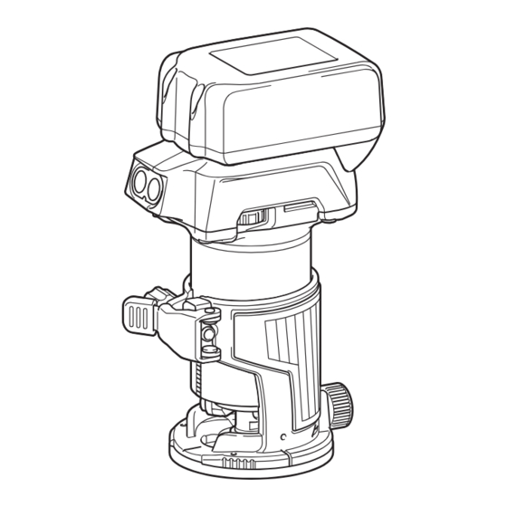
- Page 1 INSTRUCTION MANUAL Cordless Trimmer DRT50 Read before use.
-
Page 2: Specifications
SPECIFICATIONS Model: DRT50 Collet chuck capacity 6 mm, 8 mm, 1/4", or 3/8" No load speed 10,000 - 30,000 min Overall length 226 mm Rated voltage D.C. 18 V Standard battery cartridge BL1815N / BL1820 / BL1820B / BL1830 / BL1830B / BL1840 / BL1840B / BL1850 / BL1850B / BL1860B Net weight 1.8 - 2.1 kg... - Page 3 Use personal protective equipment. Always Disconnect the plug from the power source wear eye protection. Protective equipment such and/or remove the battery pack, if detachable, as a dust mask, non-skid safety shoes, hard hat or from the power tool before making any adjust- hearing protection used for appropriate conditions ments, changing accessories, or storing power will reduce personal injuries.
- Page 4 (gained from repeated use) replace causing fires, personal injury and damage. It will strict adherence to safety rules for the subject also void the Makita warranty for the Makita tool and product. MISUSE or failure to follow the safety charger. rules stated in this instruction manual may cause serious personal injury.
-
Page 5: Functional Description
Tips for maintaining maximum CAUTION: Always install the battery cartridge battery life fully until the red indicator cannot be seen. If not, it may accidentally fall out of the tool, causing injury to Charge the battery cartridge before completely you or someone around you. discharged. Always stop tool operation and charge the battery cartridge when you notice CAUTION: Do not install the battery cartridge... - Page 6 Overload protection Speed adjusting dial When the battery is operated in a manner that causes The rotation speed of the tool can be changed by turn- it to draw an abnormally high current, the tool automat- ing the speed adjusting dial. The table below shows ically stops without any indication. In this situation, turn the number on the dial and the corresponding rotation the tool off and stop the application that caused the tool speed.
-
Page 7: Adjusting Cutting Depth
Loosen the stopper pole fixing nut, then pull up the Adjusting cutting depth stopper pole while pressing the feed button. To adjust the cutting depth, open the lock lever, then move the tool base up or down by turning the adjusting screw. After the adjustment, close the lock lever firmly. ► 1 . Stopper pole 2. Fixing nut 3. Feed button Push down the tool until the tip of the trimmer bit touches the flat surface, and then turn the fixing lever to ► 1 . Lock lever 2. Adjusting screw secure the tool. - Page 8 Slide the depth pointer so that the pointer indi- Turn the head of the stopper pole to obtain the cates "0" on the scale. desired depth. To increase the depth, turn the head counterclockwise. To decrease the depth, turn the head clockwise.
- Page 9 ASSEMBLY CAUTION: Always be sure that the tool is switched off and the battery cartridge is removed before carrying out any work on the tool. Installing or removing trimmer bit NOTICE: Do not tighten the collet nut without inserting the bit. The collet cone may break. Insert the trimmer bit all the way into the collet cone.
- Page 10 To remove the base, follow the installation procedure NOTE: You can use the trimmer base (resin) as an in reverse. optional accessory as shown in the figure. When using the trimmer base (resin), loosen or tighten the CAUTION: When using the tool with the trim- thumb nut instead of opening or closing the lock lever. mer base, be sure to install the dust nozzle on the trimmer base.
- Page 11 Remove the collet nut and the collet cone. Open the lock lever of the offset base, then insert the tool into the offset base. ► 1 . Lock lever ► 1 . Collet nut 2. Collet cone Mount the belt to the pulley by rotating the belt Install the pulley on the tool by pressing the shaft manually.
- Page 12 Attach the base plate by tightening the screws. ► 1 . Pulley 2. Belt ► 1 . Base plate Installing or removing the plunge Insert the collet cone and the trimmer bit into the base offset base, and then tighten the collet nut. Optional accessory Open the lock lever of the plunge base, then insert the tool into the plunge base all the way aligning the...
-
Page 13: Operation
Installing or removing the parallel OPERATION ruler on the plunge base Optional accessory Using the tool with the trimmer base Insert the guide bars into the holes in the plunge base, and then tighten the wing bolts. To remove the ruler, Set the tool base on the workpiece without the trimmer follow the installation procedure in reverse. - Page 14 Using the straight guide Move the tool with the straight guide flush with the side of the workpiece. Optional accessory Assemble the straight guide with the bolt and the wing nut. If the distance (A) between the side of the workpiece and the cutting position is too wide for the straight guide, or if the side of the workpiece is not straight, the ► 1 .
- Page 15 For cutting circles between 121 mm and 221 mm in Place the templet guide on the base, and then radius. attach the base plate by tightening the screws. ► 1 . Center hole NOTE: Circles between 172 mm and 186 mm in radius cannot be cut using this guide.
- Page 16 Loosen the clamp screw and adjust the distance between the trimmer bit and the trimmer guide by turn- ing the adjusting screw (1 mm per turn). At the desired distance, tighten the clamp screw to secure the trimmer guide. ► 1 . Trimmer bit 2. Templet guide 3. Distance (X) 4. Outside diameter of templet guide Using the trimmer guide ► 1 . Adjusting screw 2.
- Page 17 Using the tilt base plate with the Using the trimmer base with the trimmer base offset base plate and grip To use the trimmer base with a square base plate, The offset base plate can also be used with a trimmer remove the base plate from the tilt base, and then base and a grip attachment (optional accessory) for attach it to the trimmer base.
- Page 18 Operate the tool in the same way as the straight guide for the trimmer base. ► 1 . Screw 2. Knob type grip Using the tool with the plunge base Using the templet guide Optional accessory Always hold the grips firmly with both hands during Loosen the screws on the base and remove them. operation.
-
Page 19: Maintenance
NOTICE: Never use gasoline, benzine, thinner, alcohol or the like. Discoloration, deformation or cracks may result. To maintain product SAFETY and RELIABILITY, repairs, any other maintenance or adjustment should be performed by Makita Authorized or Factory Service Centers, always using Makita replacement parts. 19 ENGLISH... -
Page 20: Optional Accessories
OPTIONAL ACCESSORIES Straight bit CAUTION: These accessories or attachments are recommended for use with your Makita tool specified in this manual. The use of any other accessories or attachments might present a risk of injury to persons. Only use accessory or attachment for its stated purpose. If you need any assistance for more details regard- ing these accessories, ask your local Makita Service Center. - Page 21 "V" Grooving bit Corner rounding bit θ θ 1/4" 90° Unit: mm 1/4" Drill point flush trimming bit 1/4" Unit: mm Chamfering bit θ 1/4" θ Unit: mm 30° Drill point double flush trimming bit 45° 60° Unit: mm 1/4" Unit: mm 21 ENGLISH...
- Page 22 Cove beading bit Ball bearing chamfering bit θ θ 45° 1/4" Unit: mm 60° Ball bearing flush trimming bit Unit: mm Ball bearing beading bit 1/4" Unit: mm Ball bearing corner rounding bit Unit: mm Ball bearing cove beading bit 1/4"...
- Page 23 Ball bearing roman ogee bit Unit: mm 23 ENGLISH...
- Page 24 Makita Corporation 885585E5 20180621 www.makita.com...