Table of Contents
Advertisement
Quick Links
TURBO HD
D0T Series Turret Camera
User Manual
User Manual
Thank you for purchasing our product. If there are any
questions, or requests, do not hesitate to contact the
dealer.
This manual applies to the models below:
Model
DS-2CE56D0T-I2FB
DS-2CE56D0T-I2PFB
This manual may contain technical incorrect places or
printing errors, and the content is subject to change
without notice. The updates will be added to the new
version of this manual. We will readily improve or update
the products or procedures described in the manual.
0100001090102
Advertisement
Table of Contents

Related Manuals for HIKVISION DS-2CE56D0T-I2FB


Summary of Contents for HIKVISION DS-2CE56D0T-I2FB
- Page 1 This manual applies to the models below: Model DS-2CE56D0T-I2FB DS-2CE56D0T-I2PFB This manual may contain technical incorrect places or printing errors, and the content is subject to change without notice. The updates will be added to the new version of this manual.
- Page 2 Regulatory Information FCC Information Please take attention that changes or modification not expressly approved by the party responsible for compliance could void the user’s authority to operate the equipment. FCC compliance: This equipment has been tested and found to comply with the limits for a Class A digital device, pursuant to part 15 of the FCC Rules.
- Page 3 Safety Instruction These instructions are intended to ensure that user can use the product correctly to avoid danger or property loss. The precaution measure is divided into “Warnings” and “Cautions”. Warnings: Serious injury or death may occur if any of the warnings are neglected.
- Page 4 While in delivery, the camera shall be packed in its original packing, or packing of the same texture. Mark Description Table 0-1 Mark Description Mark Description DC Voltage...
-
Page 5: Product Features
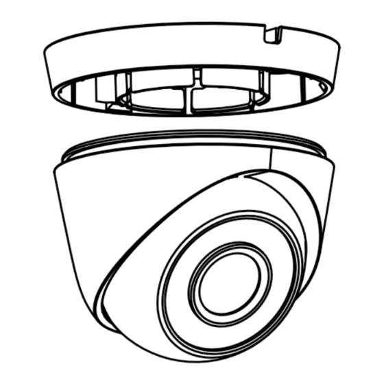
1 Introduction 1.1 Product Features The main features are as follows: High performance CMOS sensor IR cut filter with auto switch OSD menu with configurable parameters Auto white balance SMART IR mode 3-axis adjustment 1.2 Overview Mounting Power Cord 12 VDC... -
Page 6: Installation
2 Installation Before you start: Make sure that the device in the package is in good condition and all the assembly parts are included. Make sure that all the related equipment is power-off during the installation. Check the specification of the products for the ... - Page 7 Figure 2-3 Attach the Mounting Base to Ceiling Note: The supplied screw package contains self-tapping screws, and expansion bolts. For cement wall/ceiling, expansion bolts are required to install the camera. For wooden wall/ceiling, self- tapping screws are required. 5.
- Page 8 3. Secure the mount on the wall. Figure 2-6 Secure the Mount on the Wall 4. Install the mounting base of the camera to the mount, and secure them with two M4 screws. Figure 2-7 Install the Mounting Base to the Mount 5.
-
Page 9: Menu Description
3 Menu Description Follow the steps below to call the menu. Note: The actual display may vary with your camera model. Steps: 1. Connect the camera with the TVI DVR, and the monitor, shown as the figure 3-1. Figure 3-1 Connection 2. -
Page 10: Exposure Mode
Brightness refers to the brightness of the image. The higher the value is, and more brighter the image is. EXPOSURE MODE You can set the EXPOSURE MODE to GLOBAL, BLC, or HLC. GLOBAL GLOBAL refers to the normal exposure mode which adjusts lighting distribution, variations, and non-standard processing. -
Page 11: Image Mode
Figure 3-2 DAY/NIGHT COLOR The image is colorful in day mode all the time. VIDEO SETTINGS Move the cursor to VIDEO SETTINGS and click Iris+ to enter the submenu. IMAGE MODE, CONTRAST, SHARPNESS, COLOR GAIN, DNR, and MIRROR are adjustable.