Advertisement
Available languages
Available languages
Quick Links
APPLICATION
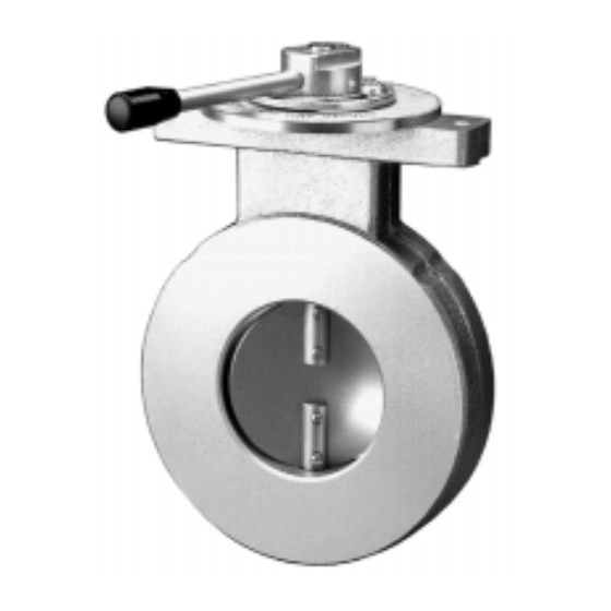
These series manually operated butterfly valves are used to
control and govern the burner airlock of gas burners. The
VF5000 Series can be equipped with the MT4000 Series
and MF4000 Series servomotors. The choice of the servo
motor depends on the working pressure and size of the
butterfly valve. The MF4000 Series is typically used in 360
mbar maximum working pressure applications and on sizes
DN50 and larger.
SPECIFICATIONS
Models
VF5000A3
Dimensions
See Figure. 1. Installation drawing VF5000A on page 2.
Pipe sizes
Inlet and outlet flanged connection DN25 up to DN150
according to PN16 ISO 7005--1.
Capacity
See Fig. 2. Capacity curves VF5000A Series on page 5.
UNIVERSAL GAS VALVES
MANUALLY OPERATED BUTTERFLY VALVE
Maximum operating pressure
500 mbar
Torsion and bending stress
Pipe connections meet group 2 according to EN161
requirements.
Ambient temperature range
--15 ... 100 °C
Valve body
Aluminium alloy die--cast
Standards and Approvals
The VF5000 Series manually operated butterfly valves
conform with the following EC directives:
• Gas Appliance Directive (90/396/EEC)
PIN: CE--0063AR1583
INSTALLATION
See Figure 1. Installation drawing VF5000A on page 2.
IMPORTANT
1. Read these instructions carefully, failure to follow
the instructions could damage the product or
cause hazardous condition.
2. Check the ratings given in the instructions and on
the product to make sure the product is suitable
for your application.
3. The installation has to be carried out by qualified
personnel only.
4. Carry out a thorough checkout when installation
is completed.
Mounting and orientation
The gas valve can be mounted in all positions (only without
motor).
Mounting location
The distance between the gas valve and wall/ground must be
at least 30 cm.
WARNING
!
Turn off gas supply before installation.
Main gas connection
1. Take care that dirt does not enter the gas valve during
handling
2. Place the gaskets. If necessary grease it slightly to
keep it in place.
3. Mount the gas valve between the flanges using the
bolts for each flange.
VF5000 Series
INSTRUCTION SHEET
MU1R--9147 9610R0--NE
Advertisement

Related Manuals for Honeywell VF5000 Series


Summary of Contents for Honeywell VF5000 Series
- Page 1 These series manually operated butterfly valves are used to personnel only. control and govern the burner airlock of gas burners. The VF5000 Series can be equipped with the MT4000 Series 4. Carry out a thorough checkout when installation and MF4000 Series servomotors. The choice of the servo is completed.
-
Page 2: Installation
Overall dimensions (mm) Passing *K = diameter bolt circle Fig. 1. Installation drawing VF5000A Torsions-- und Biegespannung WARNING Die Rohranschlüsse entsprechen den Anforderungen nach EN161, Gruppe 2. Tightness test after installation Umgebungstemperaturbereich spray all pipe connections and gaskets with a gas --15 ... -
Page 3: Installazione
2. Bringen Sie die Dichtungen an. Nötigenfalls leicht INSTALLAZIONE einfetten, um sie an ihrem Platz zu halten. 3. Montieren Sie die Gasklappe zwischen den Flanschen Vedi Figura 1. a page 2 del disegno d’installazione del mit Hilfe der zu jedem Flansch gehörenden Schrauben. VF5000A IMPORTANTE WICHTIG... -
Page 4: Specifications
VF5000A3 4. Effectuez un contrôle minutieux lorsque Dimensions l’installation est terminée. Voir la Fig. 1.Dimensions VF5000 Series, page 2 Montage et orientation Dimensions des tuyaux Il n’y a pas de restriction quant à l’angle de montage du Entrée et sortie avec raccord bridé de DN25 à DN150, monteur. - Page 5 30 40 50 60 80 600 800 4000 6000 8000 10000 1000 2000 3000 6000 Fig. 2. Capacity curves VF5000 Series (capacity in m /h air at p=2,5 mbar (SG=1 at 1013 mbar, 15°) +HOSLQJ <RX &RQWURO <RXU :RUOG MU1R--9147 9610RO--NE...