Honeywell VC Series Installation Manual
Zone valves
Hide thumbs
Also See for VC Series:
- Manual (4 pages) ,
- Installation instructions manual (10 pages) ,
- Installation instructions manual (22 pages)
Table of Contents
Advertisement
Quick Links
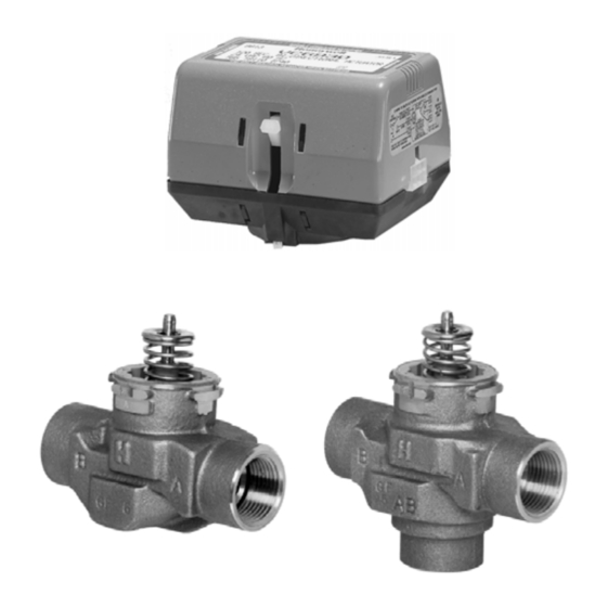
VC actuator
2-way
VC valve body
Design
VC Series zone valves consist of:
• 2-way or 3-way valve housing available with various
connection ends
• Spindle and cartridge assembly
• Actuator with cable or Molex™ socket
• Pipe fittings (most versions)
Materials
• Valve housing made of bronze
• Spindle made of stainless steel
• Cartridge made of Ryton™ (polyphenylene sulphide) and
Noryl™ (polyphenylene oxide)
• O-ring seals made of EPDM rubber
• Actuator cover made of Noryl™ (94V-0)
• Actuator base made of Ryton™ (94V-0)
Honeywell • All rights reserved
BALANCED 2-WAY AND 3-WAY HYDRONIC VALVES
3-way
VC valve body
Zone Valves
Application
Honeywell VC Series balanced 2-position hydronic valves are
used in domestic and small commercial heating and cooling
applications to control the flow of hot and/or cold water. They
consist of an actuator, valve and a cartridge assembly
2-way valves are designed for on-off zone control of domestic
systems. 3-way valves can be piped for either diverting or
mixing valve applications in domestic central heating and/or
cooling systems. Both versions can be used to control indi-
vidual fan coil, radiator, space heater or convector applica-
tions. Depending on the model selected they can be con-
trolled by a low or line voltage SPST or SPDT controller such
as a room thermostat, aquastat or flow switch.
VC Series hydronic valves are designed to take advantage of
sinusoidal valve actuator travel, and therefore operate silently
and reduce water hammer. Through internal logic the actua-
tor only takes power while driving the valve to the com-
manded position.
The actuator head is removable without affecting the integrity
of the water system. All actuator versions are interchangeable
with any valve body, offering the highest flexibility for boiler
production line assembly, and maintenance. The valve piston
construction allows for port sealing that is independent of the
differential pressure across the valve. Flow through the 2-way
valve can be in either direction, so the ports are not desig-
nated. 3-way valves are suitable for both diverting water from
AB to A or B, and from A or B to AB.
Features
• Rugged design
• Control by a low or line voltage SPST or SPDT
controller
• Minimal actuator power consumption
• Pressure differential up to 4 bar
• Double insulated actuator
• Quick connect electrical connections
• Quick and easy replacement of moving parts
• Actuator head installation does not require draining of
the system
• High flow rate capacity
VC Series
PRODUCT DATA
EN0H-0327GE25 R0206
Advertisement
Table of Contents

Related Manuals for Honeywell VC Series


Summary of Contents for Honeywell VC Series
- Page 1 SPST or SPDT controller such as a room thermostat, aquastat or flow switch. VC Series hydronic valves are designed to take advantage of sinusoidal valve actuator travel, and therefore operate silently and reduce water hammer. Through internal logic the actua- tor only takes power while driving the valve to the com- manded position.
-
Page 2: Specifications
B. When actuator is not mounted port A is closed. Function VC Series 2-position hydronic valves are used in domestic a 3-way valve with the piston driven down port B is sealed, and small commercial applications to control the flow of hot allowing flow between port AB and port A. - Page 3 3 mm in all Fig. 4. Logic sequence diagram with 2-wire + common Fig. 3. Logic sequence diagram with 3-wire actuator for actuator for SPST contoller SPDT contoller Honeywell • All rights reserved EN0H-0327GE25 R0206...
-
Page 4: Ordering Information
Customisation specifier – see Valve Selection Chart column A see Valve Selection Chart column D Body specifier – Cartridge specifier – see Valve Selection Chart column B see Valve Selection Chart column C EN0H-0327GE25 R0206 Honeywell • All rights reserved... - Page 5 VC SERIES Valve Selection Chart Honeywell • All rights reserved EN0H-0327GE25 R0206...
-
Page 6: Installation
4. Install the new actuator head by reversing process in (3). Fig. 8. Latch mechanism 5. Reconnect leadwires or Molex™ connector. 6. Restore power. EN0H-0327GE25 R0206 Honeywell • All rights reserved... -
Page 7: Adjustment And Testing
Checkout NOTE: Honeywell hydronic valves are designed and tested for silent operation in properly designed and in- 1. Raise the set point of the thermostat above room tem- stalled systems. However, water noises may occur perature to initiate a call for heat. -
Page 8: Flow Diagrams
VC SERIES Flow Diagrams Fig. 9. Valve pressure loss characteristic Port flow (%) Travel (%) Fig. 10. Typical 3-way valve diverting characteristic at constant pressure on port AB CALOR SRL ACS Control Products Str. Progresului nr. 30-40, sector 5, Bucuresti Honeywell GmbH tel: 021.411.44.44, fax: 021.411.36.14...