Table of Contents
Advertisement
Quick Links
Advertisement
Table of Contents

Related Manuals for Hitachi EC2-605


Summary of Contents for Hitachi EC2-605
- Page 1 HITACHI MAINTENANCE CONSOLE INSTRUCTION MANUAL For Models: EC2-605/EC3-605/EC4-605 Issue years August, 2004 Maintenance Manual No. ELM04-04R5 Classification code 11 Classification name Display operation instrument Urban Planning & Development Systems Company H i t a c h i L t d .
- Page 2 “Hitachi Maintenance Console” is designed to indicate the conditions of an elevator, escalator and other, and carry out their maintenance work. Hitachi Ltd. shall not be liable to any defect that may occur as the result of operation other than stated in the manual, to which your understanding is requested in advance.
-
Page 3: Table Of Contents
CONTENTS 1. Outline of Hitachi Elevator Maintenance Console・・・・・・・・・・・・・・ 1.1 Applicable Models・・・・・・・・・・・・・・・・・・・・・・・・・・ 1.2 Accessories・・・・・・・・・・・・・・・・・・・・・・・・・・・・・ 1.3 Initialization ・・・・・・・・・・・・・・・・・・・・・・・・・・・・ 1.4 Cautions ・・・・・・・・・・・・・・・・・・・・・・・・・・・・・・ 2. Name of the Sections and their Functions・・・・・・・・・・・・・・・・・・ 2.1 (1)Display ・・・・・・・・・・・・・・・・・・・・・・・・・・・・・ 2.2 (2)Functional Selector Switch ・・・・・・・・・・・・・・・・・・・・ 2.3 (3) Power Button/(4) Operation Button ・・・・・・・・・・・・・・・・... -
Page 4: Outline Of Hitachi Elevator Maintenance Console
1. Outline of Hitachi Maintenance Console This manual describes cautions and the method of using Hitachi Maintenance Console (hereinafter referred to as Maintenance Console). Please read this manual carefully before actually carrying on elevator maintenance work by using the maintenance console. -
Page 5: Accessories
1. Outline of Hitachi Maintenance Console 1.2 Accessories Check that the following 4 items illustrated are included in the accessory package: (1) Main unit, Hitachi Maintenance Console (2 ) Special connecting cable to the elevator (3 ) Four (4) UM3 dry batteries (including 2 spare batteries) (4 ) Instruction manual (this manual) ... -
Page 6: Initialization
1. Outline of Hitachi Maintenance Console 1.3 Initialization ● Enter the name of the service country, etc. to the name plate on the back of the console. Individual company is free to use this name plate for the purpose of Singapore N o. -
Page 7: Cautions
● When not using for an extended period of time, remove batteries from the battery box. Remove low batteries from the battery box promptly or leakage, etc. may cause a failure. ● Never disassemble or modify the console. Hitachi Ltd. is not liable to a failure caused by the disassembly by user. -
Page 8: Name Of The Sections And Their Functions・・・・・・・・・・・・・・・・・・
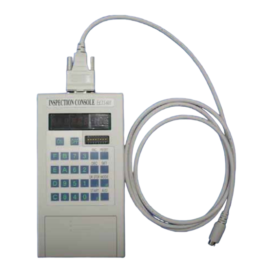
2. Name of the Sections and their Functions The diagram below shows the configuration of the Maintenance Console. This Section describes the names of the sections and their main functions. Upper Surface (6) Connector (D-sub9 pins) Side MAINTENANCE CONSOLE (1) Display ... -
Page 9: 1)Display
2. Name of the Sections and their Functions 2.1 (1) Display A 9-digit display for the elevator state of operation and the address/data during implementation of various adjustments Example of display – Operating state of the elevator (4th and 5th ... -
Page 10: 3) Power Button/(4) Operation Button
2. Name of the Sections and their Functions 2.3 (3) Power Button/(4) Operation Button Power ON-OFF button. Pressing ON button for about 1 second or longer turns the Maintenance Console ON. Pressing OFF button while the power is ON, the console is turned OFF. ... -
Page 11: 6) Connector
2. Name of the Sections and their Functions 2.5 (6) Connector Connect D-sub9 pin connector (female side) of the attached special connecting cable to the connector on top of the Console. Care should be taken for the direction of the pin connector. Connect the round 8-pin connector on the other end of the special cable to the elevator. -
Page 12: Connection Method. How To Turn The Power On-Off
Remove the cover of the elevator car operating board on the bottom floor to find the terminal for the special round connector FQ (8 pins). Connect the round connector of the special cable to this terminal. For other machine room less elevator, please consult with Hitachi, engineer. ... - Page 13 3. Connection Method. How to Turn the Power ON-OFF Table1: Setting of the functional selector switch(Basic setting) Machine type/Mode set No.1 No.2 No.3 No.4 No.5 No.6 No.7 No.8 Diagram UA-03/UA-04/UAG ON OUG/OUG-10T 1 ※Exclusion setting Table2 ON HVF5/UVF5S/VFI-2 ...
- Page 14 3. Connection Method. How to Turn the Power ON-OFF (3) Turn the power ON. Depress the console Power Button 1 second or longer. The Display will indicate as shown in the figure and the console is ready to use. Be sure to depress the button until the display indicates Power-On (P-On).
- Page 15 3. Connection Method. How to Turn the Power ON-OFF If error is indicated during the starting process, refer to Attachment 3 Maintenance Console Error Code List. (If Error10 is indicated as shown in the future, press any key to restart the process.) ...
-
Page 16: Elevator/Escalator Mode
4. Elevator/Escalator Mode When the power is ON by setting the functional selector switch to other than Group/Door mode according to Section 3 How to Turn the Power ON, the display will indicate the operation state of the elevator/escalator. This section describes the operation state indication. -
Page 17: Dot Indication For The Elevator
4. Elevator / Escalator Mode 4.2 Dot Indication for the Elevator This sub-section describes the dot section (position lamp) in the indication of the elevator state of operation using the following diagram and table: (Dot 9): Low-battery detection (Read Section 2.1) Table of the contents of operating state indicated with the dot section in the display Name Content... -
Page 18: Segment Indication Of The Escalator
4. Elevator / Escalator Mode 4.3 Segment Indication of the Escalator The segmented 9 digits in the display of the escalator state of operation indicate the trouble code and speed command value. This section describes them. Types other than EC4-605 are not applicable to the escalator. -
Page 19: Dot Indication For The Escalator
4. Elevator / Escalator Mode 4.4 Dot Indication of the Escalator This sub-section describes the dot section (position lamp) in the indication of the escalator state of operation using the following diagram and table: ... -
Page 20: Basic Method Of Operation
4. Elevator / Escalator Mode 4.5 Basic Method of Operation This subsection describes the basic operating method of maintenance work. MODE Execute various types of maintenance work by depressing (mode key), then entering a corresponding mode No. and depressing (set key). ... -
Page 21: Examples Of Maintenance Work Function Operation
4. Elevator / Escalator Mode 4. 6 Examples of Maintenance Work Function Operation ● Return to the operating state indication (for elevator/escalator) Use this step for returning to the operating state indication by interrupting the entry of various maintenance operations. -
Page 22: Group/Door Mode (Only Ec4-605)
5. Group/Door Mode Group/Door mode is used for adjusting the group control panel or the door. When the power is ON with the functional selector switch set to the group/door mode according to How to Turn the Power On in Section 3, the display changes to the address entry indication. -
Page 23: Basic Method Of Operation
5. Group/Door Mode ● (9th digit): Section of indication Indicates the section of data currently indicated by 1st to 8th digits. (Address indication mode): Indicates that the address is indicated to 1st -6th digits. (Data indication mode): Indicates that data corresponding to the address entered to 1st to 8th digit is being indicated. - Page 24 5. Group/Door Mode increment button/decrement button Increases or decreases the address value according to the current access size in the address indication and data indication modes. (Increment button is for an increase, decrement button for a decrease, +/-1 for byte access, +/-2 for word access and +/-4 for long word access.) This button is invalid when the access size is in undefined state before (3) data indication button is depressed.
-
Page 25: Attachment
○ 32 Load detection zero-point setting ○ ○ ○ (1): EC2-605, (2): EC3-605, (3): EC4-605 ● List of escalator mode functions (Applicable to EC4-605 only) MODE Function MODE Function MODE Function (Return to normal indication) Master microcomputer memory R/W (1W) ... -
Page 26: List Of Trouble Codes
Attachment 2 List of Trouble Codes ● List of Main Trouble Codes for the Elevator Section Code Trouble code for operation control system Trouble code for speed control system Taking-in circuit reference voltage error Same to the left A1 ... -
Page 27: List Of Maintenance Console Error Codes
Attachment 3 ● List of Maintenance Console Error Codes Indication Error content Action Illegal modification of the console detected or This console cannot be used. fault Abnormal key intake Faulty console. Contact this company for repair. ID error of connected machine type (EC1-602 Not applicable to other types of elevator. -
Page 28: Hardware Specifications
Attachment 4 Hardware Specifications ● Hardware specifications Item Specification Remarks Processor Hitachi 16-bit CPU Memory ROM/RAM 128KB No retention function Input I/F 26 points of pushbutton switches 8 points of sliding SW Output I/F ...