Table of Contents
Advertisement
Quick Links
Advertisement
Table of Contents

Related Manuals for Honeywell MA-1000


Summary of Contents for Honeywell MA-1000
- Page 1 MA-1000 MA-1000 Installation Manual M-167.1-MA1000-EN / 02.2023...
- Page 2 The use of this documentation does not grant you a licence or any other right to use any name, logo or label referred to or depicted herein. This documentation is subject to the copyright of Honeywell. The content must not be copied, published, modified, distributed, transmitted, sold or changed without the express prior written permission of Honeywell.
-
Page 3: Table Of Contents
5.4.3 Power supply and battery operation......................15 5.4.5 Mains and Batteries connection ........................16 SYSTEM COMPONENTS ......................................17 MA-1000 CPU Board AW80FR1 ................................18 MA-1000 User Board ......................................19 6.2.1 Terminal Board AW80US1 ..........................20 6.2.2 Relay outputs ................................ 21 6.2.3... -
Page 4: General / Application
Installation Manual MA-8000 M-167.2-SERIE-MA-EN Commissioning Manual MA-1000, MA-2000, MA-8000 M-167.3-SERIE-MA-EN Operation Manual MA-1000, MA-2000, MA-8000 M-167.4-SERIE-MA-EN Quick Start Guide MA-1000, MA-2000, MA-8000 M-167.5-SERIE-MA-EN Configuration Tool MA-1000, MA-2000, MA-8000 M-167.6-MA-LCD7-EN Operating and Installation Manual MA-LCD7 Repeater M-167.7-MA-CS-EN Cyber Security MA-1000, MA-2000, MA-8000 M-167.8-SERIE-MA-EN... -
Page 5: Precautions
Peripheral devices (sensors, etc.) which are not compatible with the control unit may cause damage to the control unit or cause the system to malfunction at any time. It is therefore essential to only use material which is guaranteed by Honeywell and is compatible with its control units. -
Page 6: 54: Information
Test Condition Indication of the test condition 10.2 Indication of zones in the test state 10.3 • The power supply section of the MA-1000 control unit conforms to the following EN54 EN 54-4 requirements. Function EN 54-4 reference Power supply from main source... -
Page 7: Transport Damage Inspection
MA-1000 TRANSPORT DAMAGE INSPECTION Please check all of the packaging and components for damage before commencing the assembly and installation work. Do not assemble or install visibly damaged modules and components! Danger – Electrical shock! Remove all power from the FACP before carrying out any installation work! -
Page 8: General Description
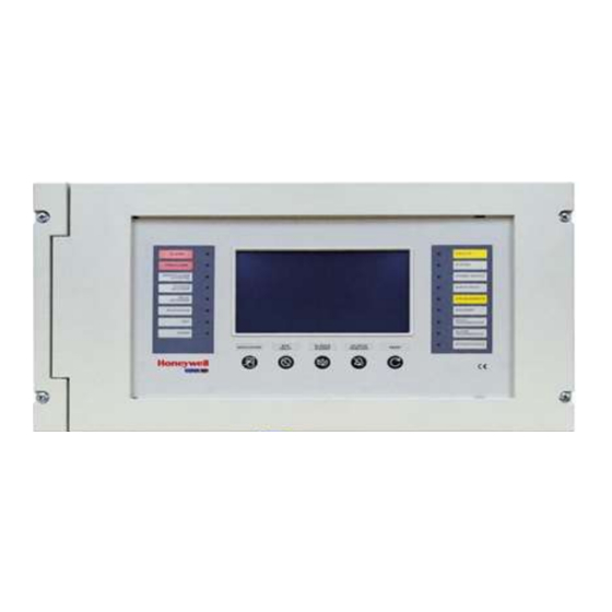
MA-1000 GENERAL DESCRIPTION MA-1000 control unit is a fire detection control unit manufactured in conformity with the EN 54-2 and EN 54-4 standards. Technical features: Multi-microprocessor system with 7" / 17,78 cm TFT display (800 x 480 with backlit), 256 colors touchscreen with keyboard simulation to program and configure the system and the following specific functions: End Delay, Silence Buzzer, Silence / Resound, Reset, Evacuation. -
Page 9: Assembly And Installation Information
MA-1000 ASSEMBLY AND INSTALLATION INFORMATION The function of the FACP depends on the country-specific version of the operating system software used for the panel and the customer data programming. • Installation and commissioning must only be carried out by a qualified electrician! •... -
Page 10: Ma-1000 Dimensions
MA-1000 4.1 MA-1000 dimensions M-167.1-MA1000-EN / 02.2023... - Page 11 MA-1000 The control unit must be installed to the wall so as to allow a clear view of the display and easy access by the operator. For example, it allows an optimal view of the display at 1,5 m height.
-
Page 12: Ma-1000 Flush Mount
4.2 MA-1000 Flush Mount MA-1000 panel can be flush mounted into a wall recess using a mounting kit MA-1BZL: Step 1: create a recess in a wall into which the MAX panel is to be semi flush mounted. The Recess Depth Z1/Z2 must be such that there is clearance to allow door to operate. -
Page 13: Labels For The Control Panel
MA-1000 4.3 Labels for the control panel The control panel of the MA-1000 is equipped with pull-out labels that provide information about the functional status of the LED. A set of labels in different languages for self-printing is available in chapter 9 of this documentation. -
Page 14: Specifications
MA-1000 SPECIFICATIONS • Ambient temperature: - 5 ° C … + 40 °C • Storage temperature: - 10 °C … + 50 °C • Relative humidity: 10 % … 95 % (without condensation) 5.1 Earthing The earthing system must be performed in conformity with CEI and ISPELS rules or rules valid in the country where the panel is installed. -
Page 15: Batteries Installation
MA-1000 5.4.2 Batteries Installation 5.4.3 Power supply and battery operation The main microprocessor of the control unit periodically checks the state of the main AC power supply source, batteries and the recharging circuit. The control unit will automatically switch to the stand-by battery source when AC mains fails. -
Page 16: Mains And Batteries Connection
MA-1000 5.4.5 Mains and Batteries connection Fuse The connection to the 230 V AC power supply mains must be performed through three-conductor cable - see figure. The identification of the earth conductor coming from the mains must be performed on the CN1 terminal block (refer to basic board topography) and must be fixed at the cabinet by means of cable –tightening strip so that it... -
Page 17: System Components
MA-1000 SYSTEM COMPONENTS AW80US1 AW80FR1 AW80PP1 MA-1000 is equipped with: • PSU board (AW80PP1) to connect the main board • Front board (AW80FR0) includes LC display 7" / 17,78 cm and the slot RTC battery backup (SA1) • Main board (AW80US0) includes connectors to front board and batteries... -
Page 18: Ma-1000 Cpu Board Aw80Fr1
MA-1000 6.1 MA-1000 CPU Board AW80FR1 CPU Board Setup Earth Removing the JDSPEC jumper causes the control unit to ignore an RS485-1 ground JDSPEC Dispersion fault (isolated). Protocol Position 1-2 Fault Relay Possibility of NO/NC contact selection through JGST Relay Alarm,... -
Page 19: Ma-1000 User Board
MA-1000 6.2 MA-1000 User Board M-167.1-MA1000-EN / 02.2023... -
Page 20: Terminal Board Aw80Us1
MA-1000 6.2.1 Terminal Board AW80US1 CNAL DC Power Supply Positive Earth It comes from power supply module – board AW80PP1 Negative Batteries Positive Battery 1 Negative Battery 1 Protection with two MFR400 series resettable fuses Positive Battery 2 Negative Battery 2... -
Page 21: Relay Outputs
MA-1000 6.2.2 Relay outputs FUNCTION CHARACTERISTICS Sounder Circuit 1 contact controlled by 24 Vcc / 1 A resistive USR2 Max 1 A resistive 30 V DC, NO / NC or supervised output 0,3 A Fused, selectable through Jumper JUSR2 (refer to basic board topography) -
Page 22: General Fault Relay
MA-1000 6.2.4 General Fault relay The General Fault relay is usually in energized state and volt-free / potential-free. It is de-energized in Fault condition. Contact range: max 30 V AC / DC, 1 A, non-inductive loads. 21 22 Settings: NO contact (Jumper JGST). -
Page 23: Usr1 And Usr2 Relays
SR1 and USR2 relays are volt fee / potential-free contacts or supervised outputs. Contact range: max 30 V AC / DC, 2 A, non-inductive loads Selection: NO, NC or supervised outputs (refer to Chapter 6.2.3) To program the activation of these outputs refer to MA-1000 Commissioning Manual. USR1 USR2... -
Page 24: Sounder Connection - Controlled Output
MA-1000 6.2.7 Sounder connection - controlled output Sounder output connections (refer to basic board topography) 1 A resettable fuse. Polarized devices balanced with diode (electronic Sounders, etc.) Connect the diode only on last sounder of the line. 1N4004 Polarity displayed are in... -
Page 25: Communication Lines With Detectors / Modules
The isolator modules allow electrical isolation of a series of devices from others to reduce the number lost in a loop short circuit condition. Input Modules The addressable inputs modules allow the MA-1000 system to monitor contacts, manual alarm call points, 4 wires conventional detectors, and several other devices with alarm contact outputs. Output modules Through addressable output modules, the MA-1000 system, by means of the programmable CBE equations, can activate the indication circuits or output relays through voltage free contacts or supervised class A controls. -
Page 26: Screen Termination
MA-1000 7.1.1 Screen Termination Good quality fire industry cable must be used incorporating drain wires or screens. The drain wires or screens must be earthed within the enclosure. Cable screen or drain wire and earthing points. Ensure the drain wires or screens are adequately grounded inside the enclosure - earthing points are provided for this purpose on enclosure to cover all the cable entry points. -
Page 27: Test Procedure For Detection Lines
MA-1000 7.2 Test procedure for detection lines Before powering the control unit lines, check the following values: A DIGITAL MULTI METER IS REQUIRED Line resistance Positive Side B Negative Side A The direct current resistance of the negative wire of the loop SHALL NOT exceed 20 Ohm. -
Page 28: System Test And Commissioning
MA-1000 7.3 System Test and Commissioning The Control unit installation must be performed after having carefully read the instructions contained in the installation and commissioning manual. Once mechanical installation of the control unit has been completed, perform the following operations: Check the correct detection line wiring through a multi-meter (refer to chapter 7.2). -
Page 29: System Periodical Maintenance
Use the arrow keys to select the item “LED” (lamp test function), press the enter key to perform the test, check that all light indications are on for some seconds. 1. Disconnect the 230 V AC mains supply from the MA-1000 control unit and check the following conditions: •... -
Page 30: Labels In Different Languages
MA-1000 LABELS IN DIFFERENT LANGUAGES In this chapter labels in different languages are shown for the control panel of the MA-1000, which can be printed 1:1. • Print the labels in original size, pay attention to the printer settings. •... - Page 31 MA-1000 M-167.1-MA1000-EN / 02.2023...
- Page 32 MA-1000 M-167.1-MA1000-EN / 02.2023...
- Page 33 MA-1000 M-167.1-MA1000-EN / 02.2023...
- Page 34 MA-1000 M-167.1-MA1000-EN / 02.2023...
- Page 35 MA-1000 M-167.1-MA1000-EN / 02.2023...
- Page 36 MA-1000 M-167.1-MA1000-EN / 02.2023...
- Page 37 MA-1000 M-167.1-MA1000-EN / 02.2023...
- Page 38 MA-1000 Notes M-167.1-MA1000-EN / 02.2023...
- Page 39 MA-1000 Notes M-167.1-MA1000-EN / 02.2023...
- Page 40 Honeywell House Skimped Hill Lane BRACKNELL M-167.1-MA1000-EN / 02.2023 Berkshire, RG12 1EB Technical changes reserved! © 2023 Honeywell International Inc.