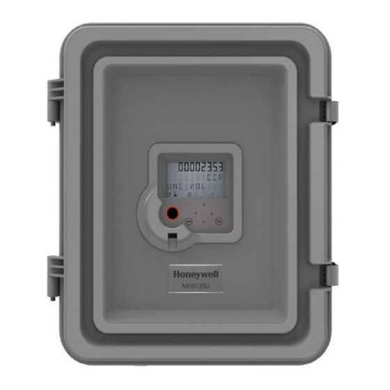
Honeywell MIWI350 Quick Start Manual
Solar power
Hide thumbs
Also See for MIWI350:
- Installation and operation manual (86 pages) ,
- Quick start manual (6 pages) ,
- Quick start manual (6 pages)
Advertisement
Quick Links
Product Overview
A built-in electronic cellular modem
Product Features
CSA C/US Class 1, Division 2, Group C & D
Compatible with MasterLink and Power Spring software
Available in UMB (Universal Mounting Bracket), Wall, Pipe, and Portable mounting options
• Internal or External Mounted Display
Modem Power Control
• Optional Backup Battery for Uninterrupted EVC Functionality
Power Supply Options
Solar Power with rechargeable Sealed Lead-Acid Battery (Refer to FD-612)
Battery - Alkaline Packs (Dual/Quad) (Refer to FD-613)
External DC Supply Input (7.5V to 24V)
This quick-start guide covers
General Safety Precautions
Close the door of the MIWI350 device properly
Check the lock and latchet, and lock the MIWI350 device properly
Check the padlock properly while locking the MIWI350 device
Safety and Hazardous Information
Warning
Caution
MIWI350 Solar Power Quick Start Guide
or Electronic Recorder
(Refer to FD-614)
Solar Power with rechargeable Sealed Lead-Acid Battery option only.
Advertisement

Related Manuals for Honeywell MIWI350


Summary of Contents for Honeywell MIWI350
- Page 1 Solar Power with rechargeable Sealed Lead-Acid Battery option only. General Safety Precautions Close the door of the MIWI350 device properly Check the lock and latchet, and lock the MIWI350 device properly Check the padlock properly while locking the MIWI350 device Safety and Hazardous Information...
- Page 2 Unpacking Instrument Mounting Options mounting options: Door Assembly Lead-Acid or Alkaline Battery Pack Solar Charge Controller Case Assembly Optional Backup Battery Pack Terminal block to connect to external incoming power UMB Mount on the Meter Latch and Lock Pressure Transducers Internal/External Display Cable gland location for Modem...
- Page 3 Setting up the MIWI350 Device Release the door latches of Install UMB on Instrument Drive the device one at a time, and gas meter (if applicable) open the door of the device Route the pulse input/output cables through the glands (if applicable)
-
Page 4: Battery Installation
WARNING: Please perform the No Load Battery Voltage measurement in an area rendered Non-Hazardous. Please Exercise Caution to ensure the Battery Terminals do not come in contact in any metal other objects during the measurement/handling. (-cw) check (+cw) Configure modem/EC/ERX350/HMI settings (For more information, refer MIWI350 Installation and Operational Manual - FD-610) - Page 5 Reference Wiring Diagrams Solar Power Supply Wiring with MIWI350-EC or MIWI350-ER 40-6169-3 40-6169-2 CONNECT CONNECT SOLAR SOLAR PANEL PANEL POWER POWER CONNECTOR CONNECTOR SOLAR POWER with 7Ah BATTERY SOLAR POWER with 21Ah BATTERY Note: The cable color code/pin mapping are only for illustration purpose and don’t match the actual cables.
- Page 6 NOTES For more information: To learn more out oneywell s Smart Gas Metering Solutions, visit www oneywellprocess com or contact your eywell Process Solutions representative Honeywell Process Solutions 128 Kemper Me ow Drive Cincinnati, April 2019 ©2019 Honeywell International Inc...