Table of Contents
Advertisement
Quick Links
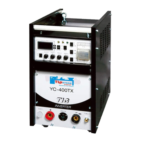
IGBT controlled DC TIG Arc Welding Power
Source
● Thank you for your purchase of Panasonic welding power source.
●Before operating this product, please read the instructions carefully and save this
manual
for future use.First of all, please read "Safety precautions" or "Safety manual".
● SPEC. No.: YC-400TX3HJF
Panasonic Welding Systems (Tangshan) Co., Ltd.
Operating Instructions
Model No.
YC-400TX
TSM50310-01
Advertisement
Table of Contents

Related Manuals for Panasonic YC-400TX


Summary of Contents for Panasonic YC-400TX
- Page 1 Source YC-400TX Model No. ● Thank you for your purchase of Panasonic welding power source. ●Before operating this product, please read the instructions carefully and save this manual for future use.First of all, please read “Safety precautions” or “Safety manual”.
- Page 2 NOTICE: MACHINE EXPORT TO EUROPE This product does not meet the requirements specified in the EC Directives which are the EU safety ordinance. Please bear in mind that this product may not be brought as is into the EU. The same restriction also applies to any country which has signed the EEA accord.
-
Page 3: Table Of Contents
CONTENT 1 . S a f e t y P r e c a u t i o n - - - - - - - - - - - - - - - - - - - - - - - - - - - - - - - - - - - - - - - - - - - - - - - - - - - - - - - - - - - - - - - 1 2.Important Safety Items----------------------------------------------------------------------2 3. -
Page 4: Safety Precaution
It is also important to ensure that equipment functions correctly at all times. Panasonic robots are designed and manufactured on the premise that contents of this manual are conformed to by users. Personnel who use any other manuals must read and understand the contents of this manual first. -
Page 5: Important Safety Items
2. Important Safety Items The following instructions must be followed carefully in case of working near the robot performing arc welding operation. WARNINGS Welding power source Observe the following instructions to prevent the hazard. This welding power source is designed and manufactured giving due consideration to safety of the product, however, it is very important to comply with all instructions, safety warnings, cautions and notes mentioned in this operating instruction. - Page 6 Against fire, explosion or blowout Observe the following cautions to prevent fires explosion or blowout. Remove any combustible materials at and near the work site to prevent them from being exposed to the spatter. If they cannot be relocated, cover them with a fireproofing cover. Do not conduct welding near combustible gases.
- Page 7 Welding wire Welding wire, especially wire tip part can cause injury. Wire extends out from the end of the welding torch and may stick into the eye, face or body. Do not perform inching operation or pull the torch switch with your eyes, face or body close to the end of the welding torch - wire may stick into your eye, face or body.
-
Page 8: Summarize
3. SUMMARIZE YC-400TX3□□□ is a DC TIG welding machine with inverter technology controlled by IGBT. Features □ □ Using PWM controlled technology which offers constant welding current and stable welding arc. □ There is an electric-shock-prevent switch in the printed circuit board, when people welding in the danger of electric shock, please turn it on that would guard the operator against electric shock. -
Page 9: Rating
4. Rating Item YC-400TX Type Rated Input Voltage Allowable fluctuation 415±10% No. of Phase Rated Frequency 50/60 14.5 Rated input STICK 21.4 12.4 Rated input STICK Rated No-Load Voltage Output current 4~400 Initial current 4~400 Pulse current 4~400 Crater current... -
Page 10: Accessories
5. Accessories 5.1 Standard accessories Type YC-400TX Name Gas hose TWG75104-□□ Operation manual TSM50310 Filter CJX30101 Adapter CJM30101-□□ 5.2 Optional accessories We manufacture and sell various attachments as optional accessories to suit a wide rang of TIG welding processes. ①Cooling system (YX-09KGC1) Feature:This system is convenient for use in situations where cooling water (i.e. -
Page 11: Preparation
6. Preparation 6.1 Power supply and connecting cable Type YC-400TX Item Supply voltage phases Three-phase Facility capacity 30 or more Fuse Switch box Earth leakage breaker or no-fuse capacity Inverter use breaker Input cable 8 or more Output cable 35 or more N.B. - Page 12 6.3 Equipment and materials required for work Prepare the following equipment and materials for welding. TIG’ welding Torch for TIG welding Products to be purchased separately Welding argon gas Products to be purchased separately Argon gas adjustor (YX-251A) Products to be purchased separately Base metal side cable [Stick welding] Products to be purchased separately Holder for stick welding...
- Page 13 select it according to the purpose in a specific case such as welding dissimilar metals. Reference for selection of filler wire diameter Welding Current (A) Filler Wire Diameter (mm) 10 — 20 — 1.0 20 — 50 — 1.6 50 — 100 1.0 —...
-
Page 14: Function
7. Function TEMP OUTPUT DISPLAY Once power switch trips auto- matically, do not turn on again. VOLT WATER POWER REPEAT CRATER WATER CHECK SELECT TORCH DISPLAY WELD WELD CUR CRATER CUR INITIAL CUR ARC FORCE CUR STICK PULSATION POWER PULSE FREQ PULSE CUR UP-SLOPE DOWN-SLOPE... - Page 15 of specified value or more is supplied. Turns on when the temperature of welding power source is too high. 7. Input volt warning lamp Turns on when input voltage is unusual (excessive, too low or be short of phase). 8. A-V display switch Control the display of the digital meter 9.
-
Page 16: Connection
8. Connection (1)TIG welding INPUT (2)DC stick welding POWER BASE METAL After wiring the output terminals, please cover them with this protective guard. -
Page 17: O P E R A T I O
9. Operation 9.1 Operation at TIG welding (a)Set the welding process switch on the front panel at "TIG welding". (b)Turn on the switch of the switch box. (c)Turn on the power switch on the front The power lamp (green) turns on. panel. -
Page 18: Maintenance And Checking
10. Maintenance and Checking Periodic maintenance and checking are recommended for safe use of the welder. The primary switch box (or no-fuse breaker) must be turned off when checking internal or external terminals. 10.1 Daily check list Take adequate countermeasures or contact dealer if any abnormality is found through the following checks: ①... - Page 19 The following points should be strictly observed in the event any of these tests are carried out in accordance with your company regulation. a. Disconnect cable from distribution box which is connected to three input terminals and short-circuit the three input terminals.
-
Page 20: Caution
11. Caution 11.1 Operation of power switch (on the front panel of machine) ① When the power switch trips out, it must not be turned on again. Contact manufacturer's agent. If the power switch is turned on again without removing the cause, it may result in burn-out of the machine. ②... - Page 21 hand.) Because of freezing, the flow switch may be broken in winter. Therefore, Disconnect torch water hose from the power supply or keep water flowing at very low pressure.
-
Page 22: Precautions For Filter
12. Precautions for filter By means of setting the attached filter to the water inlet on the rear side of the welding machine, you can prevent the inside of the water flow switch and the water conduct of torch from accumulating dust or fur. Please fix the filter in the following way. -
Page 23: Troubleshooting
13. Troubleshooting Abnormality Checking Point Contact manufacturer's agent because circuit components may be Power switch (MCB) has tripped out. broken. Power lamp does not turn on if power Power supply is not connected. switch is turned on. Fuse in switch box is blown. Also, cooling fan does not rotate. - Page 24 Polarity is not suitable. Connection of input and output terminals is ineffective. Welding current for tungsten electrode is too small compared with Arc is unstable or result of welding is not current suitable for the diameter of electrode. good. Tungsten electrode is dirty. Welding current for welding rod is too small compared with current suitable for the diameter of rod.
-
Page 25: Circuit Diagram
14. Circuit diagram... -
Page 26: Parts List
15. Parts list Mark Name Code Q’ty Power switch NDM1-63C50/3 LED (Power) DB-400G LED (Temperature& Cooling water warning) DB-400Y LED (Input current warning) DB-400Y Digital meter XL5135V-3TR Potentiometer (Arc force current adjustor) RK11K114F25C0B103 Potentiometer(Initial current) RK11K114F25C0B103 Potentiometer(Welding current) RK11K114F25C0B103 Potentiometer(Crater current) RK11K114F25C0B103 Potentiometer(Pulse current) RK11K114F25C0B103... - Page 27 Switch (Gas) SLE6A2 Pc board (Control) TSMPA179□ Pc board (Adjustor) TSMP447□ Pc board (Driver) TSM9515□ Pc board (HF generator) TSM9494□...
-
Page 28: Outline Drawing
16. Outline drawing... - Page 29 Please be absolutely sure to consult with us before attempting to relocate or resell this product to or in any EU member state or any other country which has signed the EEA accord. Panasonic Welding Systems (Tangshan) Co., Ltd. Add:Tangshan New & Hi-Tech Development Zone, Hebei, China Post Code:063020 Tel: (0315)3206017 3206066 Fax:...