
Related Manuals for Motorola Canopy Subscriber Module


Summary of Contents for Motorola Canopy Subscriber Module
- Page 1 Canopy Subscriber Module USER MANUAL Part: 5200SM-UG-E R 02 02 © 2002 Motorola, Inc. All rights reserved. Printed in the U.S.A...
- Page 2 MOTOROLA, the stylized M Logo and all other trademarks indicated as such herein are trademarks of Motorola, Inc. ® Reg. U.S. Pat & Tm. Office. Canopy is a trademark of Motorola, Inc. All other product or service names are the property of their respective owners.
-
Page 3: Table Of Contents
GETTING STARTED ....................4 Welcome .......................... 4 Features........................... 4 Packing List........................4 Warranty .......................... 4 PRODUCT DESCRIPTION..................5 Canopy Subscriber Module....................5 INSTALLATION......................6 Mount the Subscriber Module ..................6 Configure your Computer....................7 Connect the Subscriber Module..................7 Align the Subscriber Module .................... 8 CABLING........................9... -
Page 4: Getting Started
When receiving a Canopy Subscriber Module, an AC power adapter will be included. WARRANTY Motorola offers a warranty covering a period of 90 days from the date of purchase by the retail customer. If a product is found defective during the warranty period, Motorola will repair or replace the product with the same or a similar model, which may be a reconditioned unit, without charge for parts or labor. -
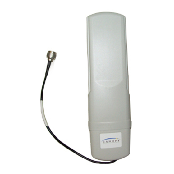
Page 5: Product Description
PRODUCT DESCRIPTION Canopy Subscriber Module The base cover of your Canopy Subscriber Module is easily removed by depressing the release lever on the back of the cover. Base Cover Base Cover Release Ethernet Lever Cable FIGURE 1 Remove the base cover as shown in FIGURE 1 to access the Ethernet connection and the Connection LED alignment indicators. -
Page 6: Installation
Access Point cluster location. 2. Mount the Canopy Subscriber Module to a secured location on the side/roof of the building. a. Illustrated in FIGURE 3 is an example of mounting the unit to an antenna mast. -
Page 7: Configure Your Computer
CONNECT THE SUBSCRIBER MODULE As with any such installed devices, the Canopy Subscriber Module and the Ethernet cable must be grounded in accordance with the latest revision of the National Electrical Code (NEC) and local electrical codes to provide some protection against damage caused by near-miss lightning strikes and other electrical discharges. -
Page 8: Align The Subscriber Module
OFF”. NOTE: The Alignment mode automatically changes back to Operation mode after 15 minutes. 6. In the Canopy Subscriber Module, check to see that the SYN/1 LED (second from right) is not intermittently blinking. If it is, slightly rotate or move the Canopy Subscriber Module unit till the LED is lit continuously. -
Page 9: Cabling
CABLING The following information describes the wiring standards for installing a Canopy system. RJ-45 Straight-Thru and RJ-45 Crossover The diagrams utilizes the EIA/TIA 568B color standard where: Wire 1 → white / orange Wire 2 → orange Wire 3 → white / green Wire 4 →... -
Page 10: Home Page
WEB PAGE INFORMATION Web pages are available for each Canopy unit. These pages are used to configure the unit and to evaluate its performance. Access the web pages by entering the IP address for a Canopy product into a standard web browser. Descriptions of these pages are provided on the following pages. •... -
Page 11: Configuration Page
CONFIGURATION PAGE The Configuration webpage contains information and configurable parameters pertaining to the operation of the product. The following are the parameters and their descriptions. Parameter Description Custom RF Frequency Determines which frequencies the subscriber module will scan. The Scan Selection (SM) List default is to scan all frequencies. -
Page 12: Ap Eval Data
AP EVAL DATA The AP Eval Data webpage contains information on what access points the subscriber module has registered to. If a subscriber module has never registered to an access point, this log will display “Current entry index: 0”. If a subscriber module has registered to an access point, the following information will be displayed per registration: Parameter Description... -
Page 13: Link Test
LINK TEST The Link Test webpage has a test for measuring the throughput and efficiency of the RF link. Entering a number into the field labeled “Duration” can choose duration for the test. This value is measured in seconds. To start the link test, click the “Start Test” button. The test will run for the set duration. -
Page 14: Specifications
SPECIFICATIONS Operating Frequency Range 5.25 to 5.35 GHz and 5.725 to 5.825 GHz U-NII Mid band Access Method TDD/TDMA Signaling Rate 10 Mbps Modulation Type High Index BFSK (Optimized for interference rejection) Carrier to Interference (C/I) 3dB, 10 BER @ -65 dBm also known as Jitter Receiver Sensitivity -83dBm 10...