Table of Contents
Advertisement
Quick Links
Owner's Manual
ACE3600 RTU
6802979C35-L
MOTOROLA , MOTO, MOTOROLA SOLUTIONS and the
Stylized M Logo are trademarks or registered trademarks of
Motorola Trademark Holdings, LLC and are used under license.
All other product or service names are the property of their
respective owners.
Copyright © 2014 All rights reserved
ab
Advertisement
Table of Contents

Related Manuals for Motorola ACE3600 RTU


Summary of Contents for Motorola ACE3600 RTU
- Page 1 6802979C35-L MOTOROLA , MOTO, MOTOROLA SOLUTIONS and the Stylized M Logo are trademarks or registered trademarks of Motorola Trademark Holdings, LLC and are used under license. All other product or service names are the property of their respective owners. Copyright © 2014 All rights reserved...
- Page 2 Motorola Solutions, Inc. Furthermore, the purchase of Motorola products shall not be deemed to grant either directly or by implication, estoppel, or otherwise, any license under the copyrights, patents or patent applications of Motorola, except for the normal non-exclusive, royalty free license to use that arises by operation of law in the sale of a product.
-
Page 3: Table Of Contents
CONTENTS GLOSSARY ................................VI DESCRIPTION................................ 1-1 .............................. 1-1 RODUCT VERVIEW ............................1-1 ENERAL ESCRIPTION ACE3600 RTU C ..........................1-3 ONSTRUCTION RTU C ..............................1-7 OMPONENTS ........................1-9 ODEL PTIONS AND CCESSORIES RF E ........................1-10 RODUCT AFETY AND XPOSURE INSTALLATION ..............................2-1 ................................ - Page 4 Contents I/O MODULES ................................ 5-1 ............................5-1 ENERAL ESCRIPTION I/O M ..................5-9 NSERTING EMOVING AN ODULE FROM THE 24V DC F ....................... 5-10 LOATING OWER UPPLY 24V DC F ..........5-12 LOATING OWER UPPLY ODULE ETAILED PECIFICATIONS DIGITAL INPUT MODULE ..........................6-1 ............................
- Page 5 Contents DIGITAL OUTPUT SBO RELAY MODULE ....................11-1 ............................11-1 ENERAL ESCRIPTION ............................ 11-4 ODULE ONFIGURATION ........................11-6 ODULE TATUS AND IAGNOSTICS I/O C ............................11-7 IRCUIT IAGRAM ..........................11-9 ODULE LOCK IAGRAM ............................11-1 ONNECTION HARTS DO SBO R ......................
- Page 6 Contents EXPANSION MODULE ............................17-1 ............................17-1 ENERAL ESCRIPTION ............................... 17-2 RONT ANEL ..................... 17-3 ODULE IRMWARE AND PERATION ODES ........................17-6 ODULE TATUS AND IAGNOSTICS ....................... 17-7 ONNECTING THE XPANSION ODULE ..........................17-8 ETTING THE RAME UMBER ........................... 17-10 USHBUTTON UNCTIONALITY ..............................
- Page 7 Contents RTU P ..........................23-8 ONFIGURATION ..........................23-9 ONTROLLING THE ODULE ACT M .......................... 23-12 ODULE PECIFICATIONS CONFIGURATION .............................. 24-1 ................................24-1 ENERAL OPTIMIZATION ..............................25-1 ................................25-1 ENERAL OPERATION ................................. 26-1 ................................26-1 ENERAL ..........................26-1 IEWING THE EGAL OTICES MAINTENANCE ..............................
-
Page 8: Glossary
GLOSSARY Advanced Control Equipment Analog Input Analog Output American Wire Gauge Data Carrier Detect Direct Frequency Modulation Digital (Discrete) Input Distributed Network Protocol Digital (Discrete) Output DPSK Differential Phase Shift Keying Expansion Microcode Interface Environmentally Preferred Product Electrostatic Discharge European Union Federal Communication Commission Front End Processor (MCP-M, MCP-T, or FIU) Field Effect Transistor... - Page 9 Glossary IPGW IP Gateway Local Area Network Light Emitting Diode Master Control Center MCP-M Motorola Communication Processor – MODBUS MDLC Motorola Data Link Communication MODBUS MODICON BUS Protocol MOSCAD Motorola SCADA MOSCAD-L Motorola SCADA-Light NEMA National Electrical Manufacturers Association (issues enclosure standards)
- Page 10 Glossary SPST Single Pole Single Trigger System Tools Suite Software Terminal Block Transmission Control Protocol TDPSK Trunked Differential Phase Shift Keying Transmit Underflow User Datagram Protocol Ultra High Frequency Universal Serial Bus Very High Frequency Wide Area Network Wire Break viii...
-
Page 11: Description
Modules with a high component density • System building tools • Interoperability with legacy MOSCAD family RTUs General Description The ACE3600 RTU is a modular unit, comprised of removable modules installed in a multi- slot frame. These modules include • Power supply • •... -
Page 12: Type
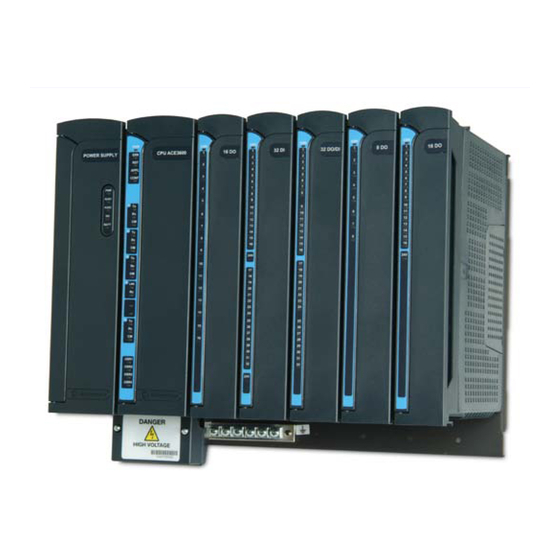
The basic (default) model includes one power supply and one CPU module. The number of I/O modules is selected as an option of the base model. Figure 1-1 provides a general view of the ACE3600 RTU with five I/O modules. POWER... -
Page 13: Ace3600 Rtu Construction
General radio interface (Conventional or Trunking, DPSK 1200, FSK 2400, DFM 4800) • Ethernet 10 Mb/s • Ethernet 10/100 Mb/s (on plug-in Port 1 only) ACE3600 RTU Construction The ACE3600 is available in various structures: • Frame which can accommodate a varied number and type of modules •... - Page 14 Description RTU Options Each RTU can include a number of options, including portable and mobile radios, and plastic accessory boxes with interface card for communication, etc. Housing/Mounting Type Capacity/Options Illustration No I/O slot frame Power supply and CPU Basic (default) model. Can be ordered with metal Can be installed on a wall.
- Page 15 Description Housing/Mounting Type Capacity/Options Illustration 8 I/O slot frame Power supply and CPU, up to 8 I/Os Can be installed on a wall or in 19” rack/enclosure. Can be ordered with metal chassis option for accessories: 6.5 or 10 Ah Lead-Acid backup battery 1 radio;...
- Page 16 Description Housing/Mounting Type Capacity/Options Illustration Large painted metal chassis Power supply and CPU, up to 7 I/Os, Enables installation of radio, 1 accessory box, backup battery and other up to 2 mobile/portable accessories. radios, Can be installed on a wall or in 6.5 or 10 Ah Lead-Acid housing.
-
Page 17: Rtu Components
For a detailed list of all ACE3600 options, see the ACE3600 price pages and ordering information. For a detailed description of the individual modules, see the appropriate chapter below. RTU Components The ACE3600 RTU can include the following components. Component Function Notes... - Page 18 Description Component Function Notes I/O expansion module Connects the I/O modules on See Expansion Module an I/O expansion frame to the chapter. CPU module on the RTU’s main frame (frame 0), directly or via an expansion LAN switch). I/O expansion power supply Connects 12V power and See Expansion Power 12V DO from the power...
-
Page 19: Model Options And Accessories
Description Component Function Notes RTU to PC RS232 cable Enables connection of the For use of the ACE3600 RTU to a PC via the RS232 Software Tools Suite (STS) port. to perform operations such as RTU configuration, system/application, download, monitoring, etc. See the ACE3600 STS User Guide. -
Page 20: Product Safety And Rf Exposure
Description Product Safety and RF Exposure Before using an ACE3600 RTU model with a radio installed, read the operating instructions and RF exposure booklet for the specific radio contained in the product. 1-10... -
Page 21: Installation
INSTALLATION General The ACE3600 RTU is shipped from the factory with the modules and plug-in ports assembled. The RTU frame is ready for mounting directly on a wall or in a customer's enclosure. The eight I/O frame can be installed on a 19" rack. -
Page 22: Mounting The Ace3600 Frame On A Wall
Figure 2-1, Figure 2-2, and Figure 2-3 show the dimensions of the various frames/metal chassis and the distances between the holes. For convenient installation of the ACE3600 RTU on a wall, allow an additional 6 cm (2.4") (in W, H) and 7 cm (2.75") (in D) around the plate. - Page 23 Installation 195 mm 234 mm 117 mm 82 mm 199.6 mm 161 mm 0 I/O Frame 2 I/O Frame 3 I/O Frame Figure 2-2 No I/O, 2 I/O, and 3 I/O Frame Installation Dimensions and Screw Holes for Installation 314 mm 391 mm 356.9 mm 278.5 mm...
-
Page 24: Installing The Ace3600 In A 19" Rack
Installation 6) Tighten all four screws with a screwdriver to secure the frame firmly against the wall. 7) Replace the removed modules in their slots. Installing the ACE3600 in a 19" Rack The following screw mount installation procedure should be used to install the ACE3600 8 I/O (19") frame / 19"... - Page 25 Installation 19” Rack Unit Metal Uprights Figure 2-5 Screws for Hanging 19" Frame in Rack Unit - Exploded View 3) Align the keyholes on the brackets with the two screws on the rack metal uprights, and hang the frame on the rack metal uprights. See Figure 2-6. Tighten the two screws to the uprights.
-
Page 26: Installing The Ace3600 In A 19" Rack (For Rtus Ordered Before October 2010)
Hanging Screws for Reinforcement Figure 2-6 Installation of ACE3600 RTU 19" Frame in Rack Unit - Exploded View Installing the ACE3600 in a 19" Rack (for RTUs Ordered before October 2010) The following screw mount installation procedure should be used to install the ACE3600 8 I/O (19") frame in a 19"... - Page 27 Installation 4) Using the supplied two screws, attach the combined brackets to the metal upright of a 19" rack unit. See Figure 2-7. Repeat on other side. Metal Upright Large Bracket Small Bracket Bracket Groove Figure 2-7 Installation of Brackets for 19" Rack Units...
- Page 28 5) Hang the 19'' metal chassis on the brackets, so that the two teeth on the back of the metal chassis hook onto the groove of the larger bracket. See Figure 2-8. Figure 2-8 Installation of ACE3600 RTU 19" Rack- Exploded View 6) From the standard rack unit, remove the two modules from the leftmost slots and the two modules from the rightmost slots.
-
Page 29: Mounting The Ace3600 8 I/O Frame On A Wall
Portable Radio Accessory Boxes Mobile Radio Battery Figure 2-9 Installation of ACE3600 RTU 19" Rack Accessories - General View Mounting the ACE3600 8 I/O Frame on a Wall 465.9 mm *Additional screws for extra fortification Figure 2-10 8 I/O Frame (19") Metal Back Installation Dimensions The following screw mount installation procedure should be used to install the ACE3600 8 I/O (19") frame on the wall. - Page 30 Installation Note: For the 8 I/O slots option and the 19" frame metal back option, the brackets for wall mount installation are included and need not be ordered separately. Procedure 2-4 How to Mount the RTU 19" Frame Metal Back on a Wall 1) Remove the CPU, Power Supply and I/O modules from the RTU frame.
-
Page 31: Mounting The Ace3600 8 I/O Frame On A Wall (For Rtus Ordered Before October 2010)
Installation Figure 2-12 19" Frame Metal Back Installation Mounting the ACE3600 8 I/O Frame on a Wall (for RTUs Ordered before October 2010) 453 mm 450 mm Figure 2-13 RTU Frame Metal Back Installation Dimensions Procedure 2-5 How to Mount the RTU 19" Frame Metal Back on a Wall The following installation procedure should be used to install the 8 I/O (19") frame on a wall, using the special wall mount brackets provided with the RTU. -
Page 32: Mounting The Ace3600 Nema 4 Housing On A Wall
The following screw mount installation procedure should be used to install ACE3600 frames in NEMA 4 housing on a wall. For convenient installation of the ACE3600 RTU with the NEMA 4 housing, allow an additional 6 cm (2.4") (in W, H) and 7 cm (2.75") (in D) around the housing. - Page 33 Installation Horizontal Bracket Installation Vertical Bracket Installation Figure 2-15 Large NEMA 4 Housing - Installation Dimensions Figure 2-16 Small NEMA 4 Housing - Installation Dimensions Procedure 2-6 How to Mount the RTU NEMA 4 Housing 1) Drill four holes in the wall at the horizontal and vertical distances shown in Figure 2-15 (for the large housing) and in Figure 2-16 (for the small housing.) 2) Using the brackets and the screws supplied in the plastic bag, fasten the mounting brackets, either horizontally or vertically, onto the four back corners of the housing.
-
Page 34: Connecting Power And Ground
Installation Figure 2-17 Mounting the NEMA 4 Housing Connecting Power and Ground All internal electrical connections except for the main power, ground and battery are performed in the factory and supplied with the RTU. The electrical interconnection diagrams are provided in the Break-Fix Procedures chapter. The procedures for the main power, ground and battery connections are provided below. - Page 35 Installation Make sure that the ground wire on the user cable is long enough to reach the grounding strip. Connecting AC/DC Main Power The power connection to all the ACE3600 power supply types is via the power junction box located on the frame beneath the power supply slot. Safety standards require that the power cable be attached to the unit at two anchor points: •...
- Page 36 Installation Anchor Point 2 Clamp Figure 2-19 RTU on Metal Chassis – Cable Anchor Point 2 Procedure 2-7 How to Connect the RTU to Main Power Source (Units with Frames and Metal Chassis) 1) Using a screwdriver, open the power junction box cover (save the screws) and unscrew the power terminals screws inside the power junction box.
- Page 37 Installation Cable to Power Supply Power Supply Cable Inlet User Power Cable Wire Terminals Anchor Point 1 Ground Cables Junction Box Figure 2-21 RTU Power and Ground Connections – All Other Installations 4) Pass the power cable to the right of the wire terminals inside the junction box, over the horizontal ridge.
- Page 38 Installation Procedure 2-8 How to Connect the RTU to Main Power Source (Units with Housing) 1) Using a screwdriver, open the power junction box cover (save the screws) and unscrew the power terminals screws inside the power junction box. 2) Insert the rubber grommet (supplied) into the threaded plastic cable gland, and place it into the hole on the bottom of the housing (from the outside.) (See Figure 2-22.) 3) Place the nut into the same hole from inside the housing and screw the nut onto the cable gland.
- Page 39 Installation 10) Secure the junction box cover with the two saved screws. 11) For all installations except the No I/O frame, loosen two screws on the grounding strip at the bottom of the metal chassis/housing and connect the ground cable to the protective ground.
-
Page 40: Connecting I/O Modules To Ground
Installation Lead acid batteries will self-discharge if they are stored without charging. Self- discharge below the manufacturer's recommended voltage will result in internal permanent damage to the battery rendering it inoperable. When this occurs, if connected to a power supply/charger, the battery may produce excessive internal heat and therefore deform and/or leak. -
Page 41: Connecting An Rtu To Ground
Installation 4) Repeat steps 1-3 for the PGND wires on all I/O modules. Connecting an RTU to Ground When an RTU is installed, individual ground wires (from the power cable and from the PGND pin on the I/O module cables) are connected to the grounding strip on the chassis. The grounding strip must then be connected to the grounding point of the cabinet or 19"... -
Page 42: Connecting The Radio
Installation Connecting the Radio A radio which is shipped in the ACE3600 is fully connected. To add a radio to the ACE3600, use the appropriate radio installation kit. For information on radio types, radio installation kits and connections, see the Radio Types and Installation Kits chapter. Opening/Closing the Housing Door The door to the small ACE3600 NEMA 4 housing is equipped with a latch or with an optional padlock accessory. -
Page 43: Installing Accessory Box Interfaces
Figure 2-26 Large ACE3600 NEMA 4 Housing/Housing with Padlock Installing Accessory Box Interfaces Cards such as RS485 interface card can be attached to the ACE3600 RTU using a plastic accessory box. The accessory box can be attached to the 19" accessories metal chassis, small/large metal chassis, or small/large NEMA housing. -
Page 44: 19" Frame Metal Back Installation Combinations
Installation Portable Radio Accessory Boxes Mobile Radio Battery Figure 2-27 Accessories Installed on a Metal Chassis 2) To remove the accessory box interface from the metal chassis, insert a screwdriver into the notch located in the snap securing the unit to the chassis. Slightly bend the snap outwards to release it from the slot, and carefully pull out the unit. - Page 45 Installation 2-25...
- Page 46 Installation Figure 2-28 19" Frame Metal Back Installation Combinations 2-26...
-
Page 47: Power Supply Module And Backup Battery
The following power supply options are available: • DC power supply low-tier (10.8-16V) • DC power supply (10.8-16V) - provided by default with the ACE3600 RTU • DC power supply (18-72V) • DC power supply (18-72V) with battery charger •... - Page 48 Power Supply Module and Backup Battery Note: The low limit of the DC power supply (10.8-16V) can be configured to 10.5V. The default is 10.8V. Common characteristics of power supply modules with battery charger: • Automatic switchover to battery on power fail •...
- Page 49 Power Supply Module and Backup Battery This converter exists only in AC or 18-72V DC PS Power Supply DC Power Supply Low-Tier Figure 3-1 ACE3600 Power Supply – General View Note: An additional power supply module for use with I/O expansion frames is described in the Expansion Power Supply Module chapter below.
- Page 50 Power Supply Module and Backup Battery Figure 3-2 below depicts a detailed view of the power supply front panel. Indication L E Ds AU X AU X B AT On/Off B utton Auxiliary Output 1A Auxiliary Output 1B Auxiliary Output 2A Auxiliary Output 2B 12V DO Control 12V Out to I/O E xpans ion...
- Page 51 Power Supply Module and Backup Battery Input/Output Connectors The front panel of the power supply module (not including DC power supply low-tier) includes the following connectors. Connector Name Description Notes Auxiliary Output 13.8V DC (±5%) @ 20°C This output is used for powering radios, User controlled power modems, etc.
- Page 52 Power Supply Module and Backup Battery Connector Name Description Notes 12V DO Control Control input that enables This input controls a dedicated 12V centralized disabling of power line that is available to all the Electrically Energized (EE) slots in the frame. In each relay DO relay outputs in selectable module, the user can mechanically DO modules.
- Page 53 Power Supply Module and Backup Battery Connector Name Description Notes 12V Out In systems with I/O Pin 1- PGND expansion, provides 12V Pin 2- 12V DO output to expansion power Pin 3- GND supplies on expansion Pin 4- MAIN (12V) frames.
- Page 54 Power Supply Module and Backup Battery The front panel of the DC power supply low-tier includes the following connectors. Connector Name Description Notes Auxiliary Output Vin=Vout This output is used for powering radios, Shorted to Power IN. modems, etc. Auxiliary Output 1B Vin=Vout This output is used for powering radios, Shorted to Power IN.
-
Page 55: Redundant Power Supply
Power Supply Module and Backup Battery LED Name Description Status Digital Output Control Power to relays is enabled (12V DO Control plug is connected) – LED ON – Green Fault state (12V DO Control plug is disconnected but power to relays is enabled) – LED ON – Red Power to relays is disabled (12V DO Control plug is disconnected) –... - Page 56 (See Replacing the Backup Battery below.) Note that the capacity test is only available for the battery types supplied by Motorola. The results of the battery capacity test can be: •...
-
Page 57: Connecting The Power Supply To A Power Source
Power Supply Module and Backup Battery Connecting the Power Supply to a Power Source The power supply can be connected to an AC or DC power source. The DC power supply low-tier can be connected to a DC power source only. The expansion power supply module is connected to another ACE36000 power supply using a DC power cable (FKN8559A/#3002360C26). -
Page 58: Harts
Power Supply Module and Backup Battery Power Supply Module Specifications The following charts detail the specifications of the various power supply modules. For specifications of the power supply module used with I/O expansion frames, see the Expansion Power Supply Module chapter below. 12V DC Power Supply Module (Default) Input Voltage DC 10.8-16 V... - Page 59 Power Supply Module and Backup Battery 18-72V DC Power Supply Modules Input Voltage 18-72 V DC Total Power 18-72 V DC Max. 60 W continuous; max. 105 W peak @ 25% duty cycle Outputs Motherboard connector (to CPU and I/O modules): 13.2 V DC ±20%, max. 4 A AUX1A/AUX1B: 13.2 V DC ±20%, max.
- Page 60 Power Supply Module and Backup Battery AC Power Supply Module Input voltage 100-240 V AC, 50/60 Hz 100-240 V AC, 50/60 Hz with 12V smart battery charger Total Power Maximum 60 W continuous; maximum 105 W peak @ 25% duty cycle Outputs Motherboard connector (to CPU and I/O modules): 13.2 V DC ±20%, max.
-
Page 61: Backup Battery
Power Supply Module and Backup Battery Backup Battery Overview The ACE3600 backup 12V Lead-Acid battery provides backup for the main input power. The battery is available in two capacities: 6.5 Ah and 10 Ah. Switching from main input power to the battery and charging of the battery is performed by the ACE3600 power supply module. - Page 62 Power Supply Module and Backup Battery Motorola battery warranty is valid only when the battery is charged with the original Motorola ACE3600 charging power supplies. Use of any other power supply/charger will void the battery warranty. Under various state or local laws, the batteries must be recycled or disposed of properly and cannot be disposed of in landfills or incinerators.
- Page 63 Power Supply Module and Backup Battery that using a battery beyond its lifespan period may cause a battery heating, leakage and/or deformation. Table 3-1: Recommended Time between Periodic Battery Recharge vs. Storage Temperature Average Storage Recharge Interval Temp (°C) (Months) Replacing the Backup Battery A battery contains diluted sulfuric acid, a toxic and corrosive substance.
- Page 64 Power Supply Module and Backup Battery Figure 3-3 Backup Batteries – Exploded View 3) Remove the old battery from the RTU. 4) Check the replacement battery visually. If the battery looks deformed, if you notice corrosion on the battery terminals, or the battery leaks, DO NOT use the replacement battery;...
-
Page 65: Cpu Module
CPU MODULE General Description The main element of the ACE3600 is the CPU module. It controls the I/O modules, processes the gathered data and communicates with the outside world. The core of the module is Freescale’s MPC8270 32-bit microprocessor which has extended communication capabilities, high speed core, DMA and floating point calculation support. -
Page 66: Front Panel
CPU Module The CPU panel includes status LEDs, user LEDs, communication port LEDs, two pushbuttons, and communication ports. The panel is covered by the module door. Figure 4-2 provides a detailed view of the CPU front panel. Pushbuttons CPU Status APPL CONF Host... - Page 67 CPU Module • Internal Ethernet port (Int 1) – Internal 100 Mb Ethernet port, (for communication between dual redundant CPUs) (CPU 3680 only) Plug-in port bays, where different types of ports can be installed: • Plug-in 1 (PI1) – fits RS232, RS485, 10 MB Ethernet, 10/100 MB Ethernet, or Radio Modem Plug-in option •...
- Page 68 CPU Module Pushbuttons The CPU includes two pushbuttons on the front panel, PB1 and PB2. These pushbuttons are used for activating and testing the modules LED, restarting the unit, erasing the user Flash memory and activating memory test. Table 4-2 describes the pushbuttons functionality.
-
Page 69: Cpu With Security
CPU Module Real Time Clock (RTC) The CPU includes a low drift RTC. The date and time are retained using an on-board rechargeable lithium battery. The CPU date and time can be set using the ACE3600 STS. The CPU can also be synchronized with other RTUs in the system, using the system clock. - Page 70 CPU Module Power-up and Restart The CPU requires DC voltage provided by the power supply module via the motherboard (when the PS switch is ON). The CPU will power-up and restart in the range of 10.8V to 16V DC. During power-up, the processor performs fast memory tests, initiates the RTU and starts the user program (if one was downloaded).
-
Page 71: Cpu Status And Diagnostics
CPU Module Power-down When the voltage provided to the CPU module drops below the minimum level, the CPU will shut down in an orderly fashion. This level is configurable for all power supply modules other than the 12V DC power supply low-tier. See the ‘Minimum DC operation voltage’ parameter in Appendix A: Site Configuration Parameters of the ACE3600 STS User Guide. - Page 72 CPU Module Figure 4-3 depicts a plug-in port board attached to the ACE3600 CPU module. Supporting Pins Plug-in 1 Supporting Pins Plug-in 2 Figure 4-3 Plug-In Port in CPU Module Procedure 4-1 describes how to connect a plug-in port to the CPU. Procedure 4-1 How to Connect a Plug-in Port to the CPU 1) Remove the CPU module from the RTU.
-
Page 73: Connecting Sram Expansion Memory To The Cpu Module
CPU Module Connecting SRAM Expansion Memory to the CPU Module In general the plug-in SRAM is ordered as an option with the RTU and is installed in the factory. However, it is also possible to add plug-in SRAM to the CPU after it is shipped from the factory. -
Page 74: Pushbutton Functionality
CPU Module Pushbutton Functionality The table below describes the use of the two pushbuttons in various scenarios, during power- up and run-time. To press a pushbutton during startup, first press the pushbutton(s), then turn on the RTU using the On/Off switch on the front panel. Keep the pushbutton(s) depressed for the required number of seconds, as specified in the scenarios below. -
Page 75: D Iagnostics
CPU Module Scenario Trigger Action Erase User During startup, press both All the user Flash memory content Flash PB1 and PB2 excluding logging files (files tagged as simultaneously until the data logging files) is erased, including the buzzer buzzes five times site configuration, user application quickly, then continuously programs, user tables, etc. -
Page 76: Cpu Leds Behavior
CPU Module CPU LEDs Behavior The table below describes the behavior of the LEDs on the CPU module. Table 4-4 ACE3600 CPU LEDs Behavior LED Name Description Status Power LED Flashing Red – Power exists; CPU FPGA not loaded. Bicolor LED (Red, Green) Green –... - Page 77 CPU Module LED Name Description Status USB Host2 LNK (link) ON – A USB device is connected. H1 LNK2 Green LED OFF – No link exists between the CPU and the MotoTrbo radio. PI1 TX Plug-in Port 1 – TX ON- Transmitting Data (transmit) Green LED...
- Page 78 CPU Module LED Name Description Status Ethernet Port 1 – RX ON – Receiving Data E1 RX (receive) In case of RAM test and startup failure, see Green LED Table 4-2 and Table 4-3. Internal Port 1 (INTR1) for ON – This CPU is the active CPU. I1 ACTV Redundancy (active) OFF –...
-
Page 79: Cpu 3610*/Cpu 3640 Module Specifications
CPU Module CPU 3610 /CPU 3640 Module Specifications Microprocessor Freescale – Power PC II MPC8270, 32-bit, extended communication capability, DMA and floating point calculation support Microprocessor Clock 200 MHz Memory Flash: 16 MB/3 MB free for user DRAM: 32 MB/10 MB free for user SRAM plug-in (Optional): 4 MB total, all free for user Real-Time Clock Full calendar with leap year support (year, month, day, hours, minutes,... -
Page 80: Cpu 3680 Module Specifications
CPU Module CPU 3680 Module Specifications Microprocessor Freescale – Power PC II MPC8270, 32-bit, extended communication capability, DMA and floating point calculation support Microprocessor Clock 200 MHz Memory Flash: 32 MB/19 MB free for user SDRAM: 128 MB/100 MB free for user SRAM plug-in (Optional): 4 MB total, all free for user Real-Time Clock Full calendar with leap year support (year, month, day, hours, minutes, seconds). -
Page 81: S Pecifications
CPU Module Operating Voltage 10.8-16 V DC (from the motherboard connector) Dimensions 56 mm W x 225 mm H x 180 mm D (2.2" W x 8.7" H x 7.1" D) Weight Approx. 0.38 Kg (0.84 Lb) Specifications subject to change without notice. 4-17... -
Page 82: I/O Modules
I/O MODULES General Description The ACE3600 RTU can include up to eight I/O modules, depending on the frame size. A variety of I/O modules are available. Additional I/O modules can be added using the I/O Expansion frame. For information, see the I/O Expansion chapter below. - Page 83 I/O Modules Figure 5-2 ACE3600 I/O Module – Front Panel (without TB Holder) I/O Module LEDs The ERR LED indicates an I/O module fault and errors. It will remain lit until all the errors have been eliminated. Diagnostic and error messages can be retrieved from the module using the ACE3600 STS Error Logger or SW Diagnostics.
- Page 84 I/O Modules Panel Terminal Block (TB) Connectors Each I/O module is equipped with a set of two, three or four TB connectors. Each TB connector has a fixed female side on the module and a male plug for the sensor/device wire connection.
- Page 85 I/O Modules 4) Clamp the open TB extractor over the desired TB connector and pull on the back handle to extract the TB connector from the I/O module. Figure 5-4 TB Extractor TB Holder and Cables The TB holder secures the male TBs neatly in place and forms a single connector plug per module.
- Page 86 I/O Modules Figure 5-5 Terminal Block (TB) Holder-Front and Back View Assembling the TB Holder Parts Procedure 5-1 Assembling the TB Holder Parts If the TB holder kit is ordered, follow the procedure below. (See Figure 5-6.) 1) Prepare the cable by cutting the wires to fit the TBs. Connect the wires of the user- assembled cables to the TBs, following the pin descriptions on the module panel label (where pin 1 is at the top of first TB and so on downwards.) 2) Place the TBs onto the left part of the TB holder plastic.
- Page 87 Attaching the TB Holder Clip to the I/O Module An optional TB holder clip can be added to the I/O module to secure the cable. Procedure 5-2 Attaching the TB Holder Clip to the I/O Module 1) Remove the I/O module from the ACE3600 RTU.
- Page 88 I/O Modules 2) Using the supplied screw, attach the TB holder clip to the bottom of the I/O module. (See Figure 5-7.) 3) Replace the I/O module in the RTU slot. I/O Module TB Holder TB Holder Clip Screw Clip Cable Pipe Figure 5-7 I/O Module with Terminal Block (TB) Holder Clip Connecting the TB Holder to the I/O Module...
- Page 89 I/O Modules 10) Label the TBs wires with any desired user notes. The wires are numbered 1-20 or 1-40 depending on the model. The wire numbers correspond to the module pins. 11) To extract the TB holder from the I/O module front panel, extend the ejector handles outward away from the module and pull on the handles.
-
Page 90: Inserting /Removing An I/O Module From The Rack
I/O Modules Each wire is color coded according to the color code pin table below. WIRE COLOR Black Green White Brown Blue Orange Yellow Purple 20-wire Gray cable White/Black White/Red White/Green White/Yellow 30-wire White/Blue cable White/Brown White/Orange White/Gray White/Purple 40-wire White/Black/Red cable White/Black/Green... -
Page 91: 24V Dc Floating Plug-In Power Supply
I/O Modules Note: The hot-swap of an I/O module in the expansion frame of an RTU which is running without a configuration from the STS (i.e. running the default configuration as from the factory) will not be successful in the following situation: If the expansion module restarts while the main CPU is running and during this restart, a I/O module is removed. -
Page 92: D Iagnostics
I/O Modules Use the ACE36000 STS Hardware Test utility to retrieve the FPGA version from the unit. If the FPGA version listed in the Module Diagnostics is lower than the version in the chart above, you must upgrade the I/O version by downloading a higher version FPGA file using the STS. -
Page 93: Dc Floating Plug-In Power Supply Module Detailed Specifications
I/O Modules 24V DC Floating Plug-In Power Supply Module Detailed Specifications Input Voltage 10.8-16 V (from I/O module) Outputs 24V floating, max. 150 mA Power Consumption Refer to Appendix D: ACE3600 Maximum Power Ratings. Efficiency 75% typical Protection Automatic output shut down on overvoltage and overcurrent Insulation Input to output: 1500 V AC Dimensions... -
Page 94: Digital Input Module
DIGITAL INPUT MODULE General Description The ACE3600 Digital Input (DI) module can have 16 or 32 inputs. The following DI modules are available. • 16 DI Fast 24V • 32 DI Fast 24V • 16 DI Fast 24V IEC TYPE 2 •... - Page 95 Digital Input Module 16 DI Module 32 DI Module Figure 6-1 ACE3600 DI Module – General View Figure 6-2 provides a detailed view of the ACE3600 DI module front panel.
-
Page 96: Di Module Configuration
Digital Input Module 16 DI Module 32 DI Module Figure 6-2 ACE3600 DI Module – Front Panel DI Module Configuration The 16 DI Fast 24V and 32 DI Fast 24V modules can handle AC and DC input signals. The user can select DC or AC operation per module. When AC configuration is selected, the Fast Capture, Counter Function and Input Filters (see below) are disabled. - Page 97 Digital Input Module Event Time Tagging Each DI can be set in the user application program’s I/O link table to trigger recording of time tagged events upon any input change of state. The time tagged events are recorded in the CPU memory and can be retrieved for various purposes.
-
Page 98: Module Status And Diagnostics
Digital Input Module Sleep Mode Each DI module can be switched by the user application program to Sleep Mode. In Sleep Mode, the module does not function and the power consumption is minimized. During Sleep mode, the user application program will get the predefined values (PDV) for each I/O. Module Status and Diagnostics In the event of DI Module failure, the I/O module ERR LED will be lit. -
Page 99: I/O Circuit Diagram
Digital Input Module I/O Circuit Diagram DI - Typical Input Circuit DI Status Full Diode Bridge Rectifier Current Limiter Fast 24V Fast 48V 255 3.32K Current 3.5mA Limiter... -
Page 100: Module Block Diagram
Digital Input Module Module Block Diagram 16 DI... - Page 101 Digital Input Module 32 DI...
-
Page 102: Connection Charts
Digital Input Module Connection Charts 16 DI 32 DI Function Function Function Function DI11 DI17 DI12 DI18 DI13 DI19 DI14 DI20 DI15 DI21 DI16 DI22 +24V DI23 COM1 DI24 PGND1 DI25 DI10 PGND1 DI10 DI26 DI11 DI27 DI12 DI28 DI13 DI29 DI14 DI30... -
Page 103: I/O Connection Diagram
Digital Input Module I/O Connection Diagram Connection of a dry contact sensor to the DI module requires “wetting” the contact with a voltage. This can be done using the 24V DC floating plug-in power supplies that can be added to the module (in 16/32 DI Fast 24V/ Fast 24V IEC TYPE 2 modules only). The 24V can be also used to power “wet”... -
Page 104: Di Module Specifications
Digital Input Module DI Module Specifications 16/32 DI FAST 24V Modules Total Number of Inputs 16 DI; 32 DI Input Arrangement Isolated groups of 16 inputs with shared common Fast Counter Inputs Inputs that can be used as fast counters: - All inputs in 16 DI module;... - Page 105 Digital Input Module 16/32 DI FAST 24V IEC 61131-2 TYPE II Modules Total Number of Inputs 16 DI 32 DI Input Arrangement Isolated groups of 16 inputs with shared common Fast Counter Inputs Inputs that can be used as fast counter: - All inputs in 16 DI module - First 20 inputs in 32 DI module Fast Counter Input Frequency...
- Page 106 Digital Input Module 32 DI FAST 48V Modules Total Number of Inputs 32 DI Input Arrangement Isolated groups of 16 inputs with shared common Fast Counter Inputs Inputs that can be used as fast counters: First 20 inputs Fast Counter Input Frequency 2.0 KHz (minimum pulse width 250 µS) Max.
-
Page 107: Digital Input 120/230V Module
DIGITAL INPUT 120/230V MODULE General Description The ACE3600 Digital Input 120/230V (High Voltage DI) module has 16 inputs. Each input can be connected to 120V or 230V (AC or DC). All the inputs are optically isolated. Each DI can be an event trigger (interrupt-driven) to a high priority fast process. The high priority fast process enables very fast activation of an output in response to an input trigger and logical conditions. -
Page 108: Di Module Configuration
Digital Input 120/230V Module Figure 7-2 provides a detailed view of the ACE3600 High Voltage DI Module front panel. Figure 7-2 ACE3600 High Voltage DI Module – Front Panel DI Module Configuration The High Voltage DI module can handle AC and DC input signals. The user can select DC or AC (default) operation per module. -
Page 109: Module Status And Diagnostics
Digital Input 120/230V Module DI Module Configuration Options The High Voltage DI module features which can be configured are listed in the table below. Some parameters are per module and some are per input. Table 7-1 ACE3600 High Voltage DI Module Configurable Features Feature Parameter Default Setting... -
Page 110: I/O Circuit Diagram
Digital Input 120/230V Module I/O Circuit Diagram High Voltage DI - Typical Input Circuit DI Status 1238Ω 10KΩ 47nF Current Circuit... -
Page 111: Module Block Diagram
Digital Input 120/230V Module Module Block Diagram 16 DI High Voltage Input Circuit COM 1-6 DI10 Control Interface DI11 DI12 COM 7-12 DI13 DI14 DI15 DI16... -
Page 112: Connection Charts
Digital Input 120/230V Module Connection Charts 16 High Voltage DI Function Function DI13 DI14 DI15 DI16 COM1-6 COM13-16 DI10 DI11 DI12 COM7-12... -
Page 113: I/O Connection Diagram
Digital Input 120/230V Module I/O Connection Diagram DI 120/230V Module DIx (input x) AC / DC Signal Source COM (Common) DI 120/230V Module Ext. Relay / Switch DIx (input x) AC / DC Signal Source COM (Common) - Page 114 Digital Input 120/230V Module Digital Input 120/230V Module Specifications High Voltage 16DI Module Total Number of Inputs 16 DI Input Characteristics IEC 61131-2 Type 1 Input Arrangement Two isolated groups of 6 inputs and one isolated group of 4 inputs. AC Input Frequency 47 –...
-
Page 115: Digital Output/Digital Input Fet Module
DIGITAL OUTPUT/DIGITAL INPUT FET MODULE General Description The Digital Output/Digital Input (DO/DI) FET module has 16 or 32 configurable user connections, organized in four groups. Each group can be configured as an 8 DO group or as an 8 DI group. The following Digital Output/Digital Input (DO/DI) FET modules are available. -
Page 116: Module Configuration
Digital Output/Digital Input FET Module Figure 8-2 provides a detailed view of the ACE3600 DO/DI FET module front panel. 16 DO/DI FET Module 32 DO/DI FET Module Figure 8-2 ACE3600 DO/DI FET Module – Front Panel Module Configuration Input/Output The following combinations can be configured in the STS site configuration (16 DO/DI). I/O combination DI location DO location... - Page 117 Digital Output/Digital Input FET Module The appropriate combination is selected as the I/O module type, when configuring the I/Os in the ACE3600 STS site configuration. DI Fast Capture Each DI can be configured as Fast Capture DI in the STS advanced I/O configuration. Fast capture causes the SCAN ladder output operation to get the first change that occurred since the previous scan.
-
Page 118: Module Status And Diagnostics
Digital Output/Digital Input FET Module Table 8-1 ACE3600 DO/DI FET Module Configurable Features Parameter Selection Default Setup Per Module/ Parameter Input Setup Location DI Fast Capture Disabled Disabled Input /Enabled configuration DI Filter 0-254 (x 0.2 mS) 50 * 0.2 mS Module (=10 mS) configuration;... -
Page 119: I/O Circuit Diagram
Digital Output/Digital Input FET Module shows the actual value of each input and output. It is also possible to change the input filter setup for the duration of the Hardware test and change the value of the DOs. In the Hardware Test utility, it is possible to set the module to Freeze Mode. In this mode the user application program will get the KLV/PDV of each input in the module instead of the actual input value. -
Page 120: Module Block Diagram
Digital Output/Digital Input FET Module Module Block Diagram 16 DO/DI FET... - Page 121 Digital Output/Digital Input FET Module 32 DO/DI FET...
-
Page 122: Connection Charts
Digital Output/Digital Input FET Module Connection Charts 16 DO/DI FET 32 DO/DI FET Function Function Function Function DO/DI1 DO/DI9 DO/DI1 DO/DI17 DO/DI2 DO/DI10 DO/DI2 DO/DI18 DO/DI3 DO/DI11 DO/DI3 DO/DI19 DO/DI4 DO/DI12 DO/DI4 DO/DI20 DO/DI5 DO/DI13 DO/DI5 DO/DI21 DO/DI6 DO/DI14 DO/DI6 DO/DI22 DO/DI7 DO/DI15... -
Page 123: I/O Connection Diagram
Digital Output/Digital Input FET Module I/O Connection Diagram DI wiring DO/DI FET Module DIx (input x) Contacts Switch / Sensor COM (Common) DO wiring DO/DI FET Module Diode Load (Inductive load) DOx (Output x) Source COM (Common) -
Page 124: Do/Di Fet Module Specifications
Digital Output/Digital Input FET Module DO/DI FET Module Specifications Total Number of I/Os 16; 32 I/O Arrangement Two or four group of 8 I/Os with shared common Each group can be configured as FET DO or dry contact DI. Selectable combinations (32 DO/DI): 32 DO/8 DI+24 DO/ 16 DI+16 DO/24 DI+8 DO/32 DI Selectable combinations (16 DO/DI): 16 DO/8 DI+8 DO/16 DI Counter Inputs... - Page 125 Digital Output/Digital Input FET Module Specifications subject to change without notice. 8-11...
-
Page 126: Digital Output Relay Module
DIGITAL OUTPUT RELAY MODULE General Description The DO Relay modules have 8 or 16 outputs. There are two types of DO relays: • Electrically Energized (EE) - the outputs return to the non-energized state in case of power off or module failure. •... - Page 127 Digital Output Relay Module 8 DO Relay 16 DO Relay Figure 9-1 ACE3600 DO Relay Module – General View Figure 9-2 provides a detailed view of the ACE3600 DO Relay Module front panel. 8 DO Relay 16 DO Relay Figure 9-2 ACE3600 DO Relay Module – Front Panel...
-
Page 128: Module Configuration
Digital Output Relay Module In the 8 DO modules, the relays of outputs 1 through 5 are Single Pole Single Throw (SPST) normally open (NO) and are referred to as the “Form A” relays. The relays of outputs 6 through 8 are Single Pole Double Throw (SPDT) and are referred to as the “Form C” relays. In the 16 DO modules, the relays of outputs 1 through 5 and 9 through 13 are Single Pole Single Throw (SPST) normally open (NO) “Form A”... - Page 129 Digital Output Relay Module 12V DO power is shut down and cannot be changed in this state. ML relays that are programmed for 12V DO operation will freeze in their current state when 12V DO power is shut down and cannot be changed. Therefore, setting the dip switch for ML will not necessarily inhibit them.
-
Page 130: Module Status And Diagnostics
Digital Output Relay Module DO Keep Last Value (KLV) and Predefined Value (PDV) Each output can be configured to KLV or to a PDV (0, 1). This value is executed when the user program stops or when the module has no communication with the CPU module. Also, the PDV can be used during normal operation to force a value on the output by ignoring the user program value (mask). -
Page 131: I/O Circuit Diagram
Digital Output Relay Module I/O Circuit Diagram DO EE Relay (SPST) - Typical Output Circuit Back Indication DO Control DO ML Relay (SPST) - Typical Output Circuit Back Indication DO Set Control DO Reset Control... - Page 132 Digital Output Relay Module DO EE Relay (SPDT) - Typical Output Circuit Back Indication DO Control DO ML Relay (SPDT) - Typical Output Circuit Back Indication DO Set Control DO Reset Control...
-
Page 133: Module Block Diagram
Digital Output Relay Module Module Block Diagram 8 DO... - Page 134 Digital Output Relay Module 16 DO...
-
Page 135: Connection Charts
Digital Output Relay Module Connection Charts 8 DO 16 DO Function Function Function Function COM1 COM6 COM1 COM9 NO10 COM2 COM2 COM10 COM7 NO11 COM3 COM3 COM11 NO12 COM4 COM8 COM4 COM12 NO13 COM5 PGND1 COM5 COM13 NO14 COM6 COM14 NC14 NO15 COM7... -
Page 136: Do Relay Module Specifications
Digital Output Relay Module DO Relay Module Specifications Total Number of Outputs 8 EE relay outputs 16 EE relay outputs 8 ML relay outputs 16 ML relay outputs Output Arrangement 8 DO: 3 X Form C (SPDT) and 5 X Form A (SPST) 16 DO: 6 X Form C (SPDT) and 10 X Form A (SPST) Contact Voltage Ratings Max. -
Page 137: Digital Output Relay 120/230V Module
DIGITAL OUTPUT RELAY 120/230V MODULE General Description The ACE3600 DO Relay 120/230V (High Voltage DO) modules have 12 outputs. Each output is switched by a relay. There are two types of DO relays: • Electrically Energized (EE) - the outputs return to the non-energized state in case of power off or module failure. - Page 138 Digital Output Relay 120/230V Module Figure 10-1 ACE3600 High Voltage 12 DO Relay Module – General View Figure 10-2 provides a detailed view of the ACE3600 High Voltage DO Relay Module front panel. 10-2...
- Page 139 Digital Output Relay 120/230V Module Figure 10-2 ACE3600 High Voltage 12 DO Module – Front Panel In the High Voltage 12 DO modules, the relays of all outputs (1 through 12) are normally open (NO) “Form A”. The physical position of each relay is monitored by the module logic, using a back indication signal which is connected to the relay’s second contact set.
-
Page 140: Module Configuration
Digital Output Relay 120/230V Module The user program can monitor the relay inhibiting status and act accordingly. Also, when the module’s relays are inhibited, any mismatch between the relay position and the output logical state is ignored. Module Configuration Relay Inhibiting for EE Relays When the dip switch on EE relays is set to 12V DO, the position of the 2-pin 12V DO Control connector on the front panel of the power supply module (see Power Supply Module chapter above) acts as a safety mechanism. - Page 141 Digital Output Relay 120/230V Module Figure 10-3 12V DO Dip Switch When S3 is set to Software Selectable mode, the inhibiting configuration is set using the module configuration in the STS Site Configuration (see Table 10-2 below). Procedure 10-1 describes how to set the 12V DO dip switch in order to enable relay inhibiting of EE relays.
-
Page 142: Module Status And Diagnostics
Digital Output Relay 120/230V Module DO Mask No /Yes Output Application Programmer I/O link table Reset DO at Disable/Enable Disable Module Site Startup configuration Relay Inhibiting Disable/Enable Disable Module Site (SW selectable) configuration Sleep Mode Each High Voltage DO module can be switched by the user program to Sleep Mode. In Sleep Mode, the module is not functioning and the power consumption is minimized. -
Page 143: D Iagram
Digital Output Relay 120/230V Module I/O Circuit Diagram HV DO EE Relay (SPST) - Typical Output Circuit Back Indication DO Control HV DO ML Relay (SPST) - Typical Output Circuit Back Indication DO Set Control DO Reset Control 10-7... -
Page 144: Module Block Diagram
Digital Output Relay 120/230V Module Module Block Diagram 12 V 12 V DO (User Controlled) Back Indication Module Control Interface NO10 NO11 NO12 10-8... -
Page 145: Connection Charts
Digital Output Relay 120/230V Module Connection Charts 12 DO Function Function NO10 Not used Not used Not used Not used NO11 NO12 Not used Not used 10-9... -
Page 146: Do Relay 120/230V Module Specifications
Digital Output Relay 120/230V Module DO Relay 120/230V Module Specifications Total Number of Outputs 12 EE relay outputs 12 ML relay outputs Output Arrangement 12 x 1 Form A Contact Power Ratings 3A @ 250 V AC, 3A @ 30 V DC, or 0.20A @ 125 V DC (resistive load) Minimum Contact Load 10.0 mA @+5.00 V DC Current... -
Page 147: Digital Output Sbo Relay Module
DIGITAL OUTPUT SBO RELAY MODULE General Description The DO Select Before Operate (SBO) Relay modules have 8 or 16 Electrically Energized (EE) relay outputs. In Electrically Energized (EE) relays, the outputs return to the non-energized state in case of power off or module failure. The following DO SBO relay modules are available: •... - Page 148 Digital Output SBO Relay Module power supply is switched to OFF, there will be no activating voltage to the relays, regardless the status of the Operate signal. For a description of the SBO feature, see Select Before Operate DOs in the ACE3600 I/Os chapter of the ACE3600 STS Advanced Features manual.
- Page 149 Digital Output SBO Relay Module Figure 11-2 provides a detailed view of the ACE3600 DO SBO Relay Module front panel. 8 DO SBO Relay 16 DO SBO Relay Figure 11-2 ACE3600 SBO Relay Module – Front Panel In the 8 DO SBO modules, the relays of the 8 outputs are Single Pole Single Throw (SPST) normally open (NO) and are referred to as the “Form A”...
-
Page 150: Module Configuration
Digital Output SBO Relay Module Note: In systems with I/O expansion, the power supplies on I/O expansion frames can be attached via DC cable to the power supply on the previous I/O expansion frame in a daisy- chain manner, or directly to the main power supply. In this case, the 12V DO control on the main power supply can control all DO EE relays in the entire RTU that were configured by dip switch for 12V DO. - Page 151 Digital Output SBO Relay Module A dual selector dip switch (S3) on the DO SBO Relay module has 4 selectable positions as described in the following tables: Table 11-1 8 DO SBO Relay Module- Dip Switch Settings Configuration mode SW 1 SW 2 12V –...
-
Page 152: Module Status And Diagnostics
Digital Output SBO Relay Module 4) Replace the DO SBO module in the rack. 5) If the new dip switch position causes the DO SBO relay power to be drawn from the 12VDO, plug the 2-pin TB back into the 12V DO Control on the front panel of the power supply module. -
Page 153: I/O Circuit Diagram
Digital Output SBO Relay Module I/O Circuit Diagram 8 DO 8 DO SBO EE Relay (SPST) - Typical Output Circuit 12V Control* Back Indication A COMA Back Indication 12V Control FGPA Processing Back Indication B COMB Check Select DO Select *Both the 12V and the Operate must be ON in order to power the circuit. - Page 154 Digital Output SBO Relay Module 16 DO 16 DO SBO EE Relay (SPST) - Typical Output Circuit Back Indication Check Select DO Select *Both the 12V and the Operate must be ON in order to power the circuit. 16 DO SBO EE Relay (SPDT) - Typical Output Circuit Back Indication Check Select DO Select...
-
Page 155: Module Block Diagram
Digital Output SBO Relay Module Module Block Diagram 8 DO 11-9... - Page 156 Digital Output SBO Relay Module 16 DO 11-10...
-
Page 157: Connection Charts
Digital Output SBO Relay Module Connection Charts 8 DO SBO 16 DO SBO Function Function Function Function NO1A NO5A COM1A COM5A COM1 COM9 NO1B NO5B NO10 COM1B COM5B COM2 COM10 NO2A NO6A NO11 COM2A COM6A COM3 COM11 NO2B NO6B NO12 COM2B COM6B COM4... -
Page 158: Do Sbo Relay Module Specifications
Digital Output SBO Relay Module DO SBO Relay Module Specifications Total Number of Outputs 8 DO: 8 EE relay outputs 16 DO: 16 EE relay outputs Output Arrangement - (two Normally Open contacts per DO) 8 DO: 2 X Form A (SPST) 16 DO: 6 X Form C (SPDT) and 10 X Form A (SPST) Contact Voltage Ratings Max. -
Page 159: Analog Input Module
ANALOG INPUT MODULE General Description The Analog Input (AI) modules have 8 or 16 inputs. The modules sample and convert analog data into digital format and transfer the digital data to the CPU module. The following modules are available: • AI ±20 mA (supports 4-20 mA) •... - Page 160 Analog Input Module 8 AI Module 16 AI Module Figure 12-1 ACE3600 AI Module – General View Figure 12-2 provides a detailed view of the AI module front panel. 8 AI Module 16 AI Module Figure 12-2 ACE3600 AI Module – Front Panel 12-2...
-
Page 161: Ai Module Configuration
Analog Input Module AI Module Configuration 50/60 Hz Filtering This parameter enables the user to configure the module to use 50 or 60 Hz filter on all inputs. AI Filter (Smoothing) This parameter enables the user to configure the level smoothing (averaging) on all inputs. It can be set to 1, 2, 4, 8, 16, 32, 64,128 samples. -
Page 162: Module Status And Diagnostics
Analog Input Module AI Module Configuration Options The AI module features which can be configured are listed in the table below. Some parameters are per module and some are per input. Table 12-1 ACE3600 AI Module Configurable Parameters Parameter Selection Default setup Per Module / Parameter... - Page 163 Analog Input Module • If both the UDF and OVF LEDs of the same channel are lit, the channel is uncalibrated. The AI module can be diagnosed and monitored using the STS Hardware Test utility. The Hardware Test verifies that the module is operational, presents the module configuration and shows the actual value of each input, including overflow and underflow.
- Page 164 Analog Input Module In 0 - 5 V Decimal Value Input Voltage Indication current inputs < -256 < -0.04 V Underflow LED ON Rated range (no LED active) 32000 +5 V > 32256 > +5.04 V Overflow LED ON In 1 - 5 V Decimal Value Input Voltage Indication...
-
Page 165: I/O Circuit Diagram
Analog Input Module I/O Circuit Diagram AI ±20 mA - Typical Input Circuit AI ±20 mA - Typical Input Circuit 124Ω PGND 51Ω AN - Channel Select AI ±10 V - Typical Input Circuit 51Ω PGND 51Ω AN - Channel Select 12-7... -
Page 166: Module Block Diagram
Analog Input Module Module Block Diagram 8 AI 12-8... - Page 167 Analog Input Module 16 AI 12-9...
-
Page 168: Connection Charts
Analog Input Module Connection Charts 8 AI 16 AI Function Function Function Function AI1+ AI5+ AI1+ AI9+ AI1- AI5- AI1- AI9- AI2+ AI6+ AI2+ AI10+ AI2- AI6- AI2- AI10- AI3+ AI7+ AI3+ AI11+ AI3- AI7- AI3- AI11- AI4+ AI8+ AI4+ AI12+ AI4- AI8-... -
Page 169: I/O Connection Diagram
Analog Input Module I/O Connection Diagram The diagram below describes the connection of two-wire and four-wire current sensors/transmitters to the Analog Input module. AI Module Shield AI+ (input x) 4 Wire Current Sensor AI - (input x) AI Module Shield AI+ (input x) 2 Wire Current... -
Page 170: Ai Module Specifications
Analog Input Module AI Module Specifications Total Number of Inputs 8 AI ±20 mA (4-20 mA) 16 AI ±20 mA (4-20 mA) 8 AI ±5 V (0-5 V, 1-5 V) 16 AI ±5 V (0-5 V, 1-5 V) Input Configuration Isolated (floating) analog inputs A to D Resolution 16 bit (including sign) -
Page 171: Analog Output Module
ANALOG OUTPUT MODULE General Description The Analog Output (AO) modules have four optically-isolated analog output channels for controlling user devices (see Figure 13-1). Each channel has two possible outputs: 0-20 mA Interface industry standard current output and 0-10 V Interface industry standard voltage output. - Page 172 Analog Output Module Figure 13-1 provides a general view of the ACE3600 AO module. Figure 13-1 ACE3600 AO Module – General View 13-2...
-
Page 173: Ao Module Configuration
Analog Output Module Figure 13-2 provides a detailed view of the AO module front panel. Vout Iout Vout Iout Vout Iout Vout Iout Figure 13-2 ACE3600 AO Module – Front Panel AO Module Configuration AO Type The analog outputs can be set to voltage, current, or raw data. See Module Status and Diagnostics for details. - Page 174 Analog Output Module The AO module value representation is as follows: In 0-20 mA current Decimal Value Output outputs Current 4000 5 mA 8000 10 mA 16000 20 mA In 0- 10 V voltage Decimal Value Output outputs Voltage 4000 2.5 V 8000 16000...
- Page 175 Analog Output Module AO Module Configuration Options The AO module features which can be configured are listed in the table below. Some parameters are per module and some are per output. Table 13-1 ACE3600 AO Module Configurable Parameters Parameter Selection Default setup Parameter Module /...
-
Page 176: Module Status And Diagnostics
Analog Output Module Module Status and Diagnostics In the event of AO Module failure, the I/O module ERR LED will be lit. The event is registered by the CPU in the Error Logger. AO Module failure status is also visible to the user application program. -
Page 177: I/O Circuit Diagram
Analog Output Module I/O Circuit Diagram AO - Typical Output Circuit Variable Current source 50Ω 330Ω Iout Floating Voltage Converter PGND D/A Control Vout Variable Voltage source 13-7... -
Page 178: Module Block Diagram
Analog Output Module Module Block Diagram 4 AO 13-8... -
Page 179: Connection Charts
Analog Output Module Connection Charts 4 AO Function Function Vout1 Vout3 Ret1 Ret3 Iout1 Iout3 PGND1 PGND1 PGND1 PGND1 Vout2 Vout4 Ret2 Ret4 Iout2 Iout4 PGND1 PGND1 PGND1 PGND1 13-9... - Page 180 Analog Output Module I/O Connection Diagram Current Output wiring AO Module Shield Iout x Device / Ret x Load Voltage Output wiring AO Module Shield Vout x Device / Load Ret x 13-10...
-
Page 181: Ao Module Specifications
Analog Output Module AO Module Specifications Total Number of Outputs 4 AO current (0-20 mA) or voltage (0-10 V) Output Arrangement Isolated floating channels, each channel can be connected as 0-20 mA or 0-10 V DC voltage D to A Resolution 14 bit Output Accuracy ±0.05% full scale @ 25ºC... -
Page 182: Mixed I/O Module
MIXED I/O MODULE General Description The ACE3600 Mixed I/O modules include a mixture of Digital Inputs, Relay Outputs and Analog Inputs on the same module. The available Mixed I/O modules are: • 16 Digital Inputs + 4 EE DO Relay Outputs + 4 Analog Inputs ( ±20 mA) •... - Page 183 Mixed I/O Module Figure 14-2 provides a detailed view of the Mixed I/O module front panel. Figure 14-2 ACE3600 Mixed I/O Module – Front Panel The Digital Input (DIs) on the Mixed I/O modules are voltage (“wet”) inputs IEC 61131-2 Type II compliant.
-
Page 184: Mixed I/O Module Configuration
Mixed I/O Module The Mixed I/O modules Analog-to-Digital conversion resolution is 16 Bit (including sign). Each input is fully isolated from the other inputs on the module and also optically isolated from the module internal circuits. The modules are fully calibrated. It is possible to test and re- calibrate the module in the field. -
Page 185: Module Status And Diagnostics
Mixed I/O Module Module Status and Diagnostics In the event of Mixed I/O Module failure, the ERR LED will be lit. This event is registered by the CPU in the Error Logger. DI Module failure status is also visible to the user application program. -
Page 186: Module Block Diagram
Mixed I/O Module Module Block Diagram Mixed I/O 14-5... -
Page 187: Connection Charts
Mixed I/O Module Connection Charts Mixed I/O Function Function COM1 COM2 COM3 DI10 COM4 DI11 DI12 AI1+ DI13 AI1- DI14 AI2+ DI15 AI2- DI16 AI3+ 24V+ AI3- COM1 AI4+ PGND1 AI4- PGND 14-6... -
Page 188: Mixed I/O Module Specifications
Mixed I/O Module Mixed I/O Module Specifications Total Number of Inputs / 16 Digital Inputs + 4 EE Relay Outputs + 4 Analog Inputs Outputs ( ±20 mA) 16 Digital Inputs + 4 ML Relay Outputs + 4 Analog Inputs ( ±20 mA) I/O Arrangement 1 group of 16 DIs with shared common... - Page 189 Mixed I/O Module AI Crosstalk Rejection Better than 80 dB between any pair of inputs AI Temperature Stability 25 PPM/ºC AI Interference Suppression Selectable 50 or 60 Hz filtering, common mode rejection > 100 dB, differential mode rejection > 50 dB Diagnostic LEDs Module error LED, Status LED per each DO and DI.
-
Page 190: Mixed Analog Module
MIXED ANALOG MODULE General Description The ACE3600 Mixed Analog modules include a mixture of Analog Inputs and Analog Outputs on the same module. The available Mixed Analog modules are: • 4 Analog Outputs + 8 Analog Inputs (±20 mA) (supports 4-20 mA) •... -
Page 191: Mixed Analog Module Configuration
Mixed Analog Module Figure 15-2 provides a detailed view of the Mixed Analog module front panel. Vout Iout Vout Iout Vout Iout Vout Iout Figure 15-2 ACE3600 Mixed Analog Module – Front Panel For a description of the AIs in the Mixed Analog modules, see the Analog Input Module chapter. -
Page 192: Module Status And Diagnostics
Mixed Analog Module Module Status and Diagnostics In the event of Mixed Analog Module failure, the ERR LED will be lit. This event is registered by the CPU in the Error Logger. AI Module failure status is also visible to the user application program. -
Page 193: Module Block Diagram
Mixed Analog Module Module Block Diagram Mixed Analog 15-4... -
Page 194: Connection Charts
Mixed Analog Module Connection Charts 4AO/8AI Function Function Vout1 AI1+ Ret1 AI1- Iout1+ AI2+ PGND1 AI2- PGND1 AI3+ Vout2 AI3- Ret2 AI4+ Iout2 AI4- PGND1 PGND2 PGND1 PGND2 Vout3 AI5+ Ret3 AI5- Iout3 AI6+ PGND1 AI6- PGND1 AI7+ Vout4 AI7- Ret4 AI8+ Iout4... -
Page 195: Mixed Analog Module Specifications
Mixed Analog Module Mixed Analog Module Specifications Total Number of I/Os 4 Analog Outputs + 8 Analog Inputs ( ±20 mA) or 4 Analog Outputs + 8 Analog Inputs ( ±5V DC) I/O Arrangement AO - each channel can be connected as 0-20 mA or 0-10 V, AI - Isolated (floating) analog inputs 14 bit AO D to A Resolution... - Page 196 Mixed Analog Module Diagnostic LEDs AO - Voltage mode LED, Current mode LED, Calibration LED per channel AI - Overflow and Underflow LED per each input, 24V Plug-in status LED The module Overflow and Underflow levels can be configured Current inputs: ±20mA / 4-20 mA Voltage inputs: ±5 V / 0-5 V /1-5 V General - Module error LED AI Input Isolation...
-
Page 197: I/O Expansion
I/O EXPANSION General Description The ACE3600 RTU includes the option of expanding the number of I/O modules controlled by a single CPU module on the main frame. The I/O expansion frames can be co-located with RTU on the main frame (installed in the same 19” rack or cabinet) or distributed in the same site (up to 50 meters from the main frame.) - Page 198 I/O Expansion Figure 16-1 provides a general view of an ACE3600 CPU with a single I/O expansion frame. The expansion module on the I/O expansion frame is connected using a crossed LAN cable to the CPU 3640 on the main frame (Port Eth1.) The expansion power supply on the I/O expansion frame is attached via DC cable to the power supply on the main frame.
- Page 199 I/O Expansion Figure 16-2 provides a general view of an ACE3600 CPU with multiple I/O expansion frames (two to seven.) The CPU on the main frame (Port Eth1) is connected using a LAN cable to the LAN switch on the main frame (Port Eth1-M). The expansion modules on each of the seven I/O expansion frames are connected using a LAN cable to the expansion LAN switch (Eth2- Eth8) on the main frame.
-
Page 200: I/O Expansion Frame
I/O Expansion In the maximal configuration, up to 110 I/Os can be connected to the ACE3600, by using two expansion LAN switches on the main frame and thirteen I/O expansion frames. See Figure 16- Main Rack Radio/Batt. Chassis Main PS (AC/DC) CPU 3640 Expansion Switch 1 Expansion Switch 2... -
Page 201: Status And Diagnostics
12V DO control, and it cannot provide power (in a daisy-chain manner) to other expansion power supplies. For guidelines on selecting the power supplies for a particular ACE3600 RTU with I/O expansion, see the ACE3600 System Planner. -
Page 202: Expansion Module
EXPANSION MODULE General Description The expansion module provides an interface from the CPU module (either directly or via the expansion LAN switch) on the ACE3600 main frame to the I/O modules on the expansion frame. This enables the CPU on the main frame to control the I/O modules on the expansion frame and process the gathered data. -
Page 203: Front Panel
Expansion Module Figure 17-2 provides a detailed view of the expansion module front panel. Module Pushbuttons MERR Status MCOM MCNF LEDs Frame Number Selector Rotary Switch Port STS1- STS Diagnostic Port LEDs Exp Eth1 - Ethernet Expansion Port Expansion ADDR Address LEDs Figure 17-2 ACE3600 Expansion Module –... -
Page 204: Module Firmware And Operation Modes
Expansion Module • Exp Eth1 (E1) - 10/100BaseT Ethernet port, used to connect to the expansion LAN switch or to the main CPU • STS 1 (STS1) – RS232 port 115200 bps, used to connect a PC running the ACE3600 STS to perform diagnostics and other STS operations (for distributed I/O), as if it is connected directly to the main CPU (i.e. - Page 205 Expansion Module The Expansion module discovers the main CPU (MCPU) via UDP/IP (broadcast). Expansion Loader Discovery succeeded- obtained self and MCPU IP address? 1. Loads the Firmware Image into RAM from the MCPU (using TCP). 2. Turns off all LEDs and runs the loaded Expansion Firmware Image. 3.
- Page 206 Expansion Module Power-up and Restart The MCOM LED (see LED description in Table 17-1) on the expansion module indicates the connection status between the expansion module and the main CPU and expansion frame initialization progress. The main CPU expects the expansion frames to complete the initialization within a configurable period of time (60 seconds default).
-
Page 207: Module Status And Diagnostics
Expansion Module For information on retrieving errors from the RTU Error Logger, see the Operation chapter of the ACE3600 STS User Guide. Restart after Erase Flash After the User Flash is erased in the main CPU, the RTU will restart with the default site configuration and all expansion modules will restart. -
Page 208: Connecting The Expansion Module
Four different Ethernet cables are available for this purpose. Choose the cable length based on the distance from the main frame to the expansion frame. • 0.6 meter (Motorola p/n FKN8561A) - This cable is for local connection of the main CPU to the expansion switch. •... -
Page 209: Setting The Frame Number
Expansion Module Setting the Frame Number The expansion module shipped from the factory is set by default to 1. If more than one I/O expansion frame is added, this frame number (also known as frame ID) must be changed. Procedure 17-1 describes how to set the expansion frame number using the rotary selector switch on the front panel of the expansion module. - Page 210 Expansion Module the frame number will not be changed. A message will be logged in the Error Logger notifying the user of the switch change (specifying the actual frame number.) If the frame number was set to a number other than 1-9/A-D before power-up, the expansion module will restart itself continually until the frame number is changed.
-
Page 211: Pushbutton Functionality
Expansion Module Pushbutton Functionality In general, the two pushbuttons on the front panel of the expansion module behave like the pushbuttons on the front panel of the CPU module, with the exception of the Erase User Flash functionality and user application access which are not available. Note: PB2 is not relevant during run time in the expansion module. -
Page 212: Leds Behavior
Expansion Module Scenario Trigger Action RAM Test During startup, press PB1. A detailed memory test of SDRAM and SRAM plug-in is performed. - At the beginning of the RAM test, the four indicator LEDs (see LEDs Location in Table 17-2) will blink three times. During the RAM test, the LEDs may blink or be lit. - Page 213 Expansion Module LED Name Description Status MERR Main CPU OFF – No new errors or warnings logged in Error Logger Status LED main CPU. Bicolor LED (Red, Green) Green – New message logged. Orange – New warning logged. Red – New error logged. Note: In systems with I/O expansion, all error messages from I/O expansion frames are periodically collected by the main CPU and...
- Page 214 Expansion Module LED Name Description Status MCNF Main CPU This LED reflects the state of the CONF LED Configuration LED in the main CPU: Bicolor LED (Red, Green) OFF – Configuration was not loaded in the main CPU. Green - Configuration was loaded in the main CPU.
- Page 215 Expansion Module Table 17-2 Expansion Module - Error Code Display on LEDs LEDs Location LED Error Code Description ERR Code 1 Invalid ID in expansion module, or incompatible board type. ADDR ERR Code 2 Timeout getting discovery response. ERR Code 3 Failed sending discovery request or getting invalid response.
- Page 216 Expansion Module Table 17-3 Expansion Module – RAM Test Error Code Display on LEDs LEDs Location LED Error Code Description ERR Code 1 ERR Code 1 = Error in Flash ERR Code 4 ERR Code 4 = Unable to boot. Corrupted bootstrap.
-
Page 217: Expansion Module Specifications
Expansion Module Expansion Module Specifications Microprocessor Freescale – Power PC II, MPC8270, 32-bit Microprocessor Clock 200 MHz Serial Port RS232C Asynch, Full Flow Control port, up to 230.4 kb/s; used for STS only Ethernet Port 10/100 Mb/s – connection to the main frame LAN Cable Category 5E shielded (FTP), up to 50 meter LEDs Display... -
Page 218: Expansion Lan Switch
EXPANSION LAN SWITCH General Description The expansion LAN switch provides an interface from the ACE3600 CPU (on the master RTU frame) to up to seven expansion modules (on I/O expansion frames), or up to 13 expansion modules when two switches are used. This enables the use of up to 110 I/O modules. The expansion modules can be co-located with the switch (installed in the same 19”... -
Page 219: Front Panel
Expansion LAN Switch L/RX Ethernet 1(M) L/RX Ethernet 2 L/RX Ethernet 3 L/RX Ethernet 4 L/RX Ethernet 5 L/RX Ethernet 6 L/RX Ethernet 7 Ethernet 8 L/RX Figure 18-2 Expansion LAN Switch – Front Panel The ACE3600 expansion LAN switch is configured to prioritize different Ethernet data frame types. -
Page 220: Inserting/Removing An Expansion Lan Switch From The Frame
Install the expansion in either of the first two I/O module slots in the main frame. The expansion LAN switch option includes a 0.6 meter Ethernet cable (Motorola p/n FKN8561A). Use this cable to connect from the Eth1 port on the main CPU to the Eth1 (M) port on the expansion switch. - Page 221 Choose the cable length based on the distance from the main frame to the expansion frame. 0.6 meter (Motorola p/n FKN8561A) - This cable is used for local connection of the main CPU to the expansion switch, or connection of the first LAN switch to the second, if such exists.
-
Page 222: Expansion Lan Switch Leds Behavior
Expansion LAN Switch Expansion LAN Switch LEDs Behavior The table below describes the behavior of the LEDs on the expansion LAN switch. Table 18-1 ACE3600 Expansion LAN Switch LEDs Behavior LED Name Description Status Error Logger Status LED OFF – No new errors or warnings. Red LED Red –... -
Page 223: Expansion Lan Switch Specifications
Expansion LAN Switch Expansion LAN Switch Specifications Ethernet Port 1-8 8 on board 10/100 Mb/s Ethernet ports (Auto crossover) LEDs Display Error LED, Port status LEDs Power Consumption Refer to Appendix D: ACE3600 Maximum Power Ratings. Module Replacement Hot swap replacement – module extraction/insertion under voltage Operating Voltage 10.8-16 V DC, (from the motherboard... -
Page 224: Expansion Power Supply Module
EXPANSION POWER SUPPLY MODULE General Description/Module Overview The expansion power supply module (10.8-16V DC) extends power from the power supply on the RTU’s main frame to the I/O expansion frame, or from one I/O expansion frame to another. This module is installed in each I/O expansion frame. Characteristics of the expansion power supply module: ... - Page 225 Expansion Power Supply Module Figure 19-2 below depicts a detailed view of the power supply front panel. Expansion Power Out Power Output to other Expansion units Power In 10.8-16 DC Main Power Input Figure 19-2 ACE3600 Expansion Power Supply – Front Panel Input/Output Connectors The front panel of the expansion power supply includes the following connectors.
- Page 226 Expansion Power Supply Module Connector Name Description Notes Power In 10.8-16V DC Cable inlet for main power cable Connect this input to the (DC) "RACK EXP" output of a regular power supply or to the "Expansion power out" of an expansion power supply, using a dedicated cable - FKN8559A (3002360C26.)
-
Page 227: Module Status And Diagnostics
Connecting the Expansion Power Supply to the Main Frame Power Supply The expansion power supply can only be connected to the power supply on the ACE3600 RTU main frame and to other expansion power supply modules. For instructions on connecting the expansion power supply, see the Connecting the Expansion Power Supply to the Main Frame Power Supply section of the Installation chapter above. -
Page 228: Expansion Power Supply Fuses
Expansion Power Supply Module DC Cable from other Power Supply 3002360C26 Figure 19-3 ACE3600 Expansion Power Supply – Ground Connection For instructions on connecting the entire site to ground, see Connecting an RTU to Ground in the Installation chapter above. Expansion Power Supply Fuses The expansion power supply includes two slow blow fuses, one 4A fuse for overcurrent protection for the I/O expansion frame and one 8A fuse for maximum current via the Power... -
Page 229: Expansion Power Supply Module Detailed Specifications
Expansion Power Supply Module Expansion Power Supply Module Specifications Input Voltage DC 10.8-16 V Outputs To Motherboard connector – +10.80 to +16.00 VDC, max. 4A To cascaded expansion power supply - +10.80 to +16.00 VDC, max. 8A Over Current 4.0 A (Slow blow fuse), protecting the expansion frame Protection 8.0 A (Slow blow fuse), protecting the cascaded expansion power supply Maximum Current... -
Page 230: Ace Ip Gateway Module
ACE IP GATEWAY MODULE General Description The ACE IP Gateway module (CPU 4600) is a Front End Processor (FEP) which enables SCADA control centers to communicate and interface with ACE3600 RTUs and legacy (MOSCAD-M, MOSCAD, and MOSCAD-L) RTUs in a control system. It acts as an interface between the MDLC world and the TCP/IP world. - Page 231 ACE IP Gateway Module Figure 20-1 ACE IP Gateway Module– General View The ACE IP Gateway front panel includes status LEDs, communication port LEDs, two pushbuttons, and communication ports. The panel is covered by the module door. Figure 20-3 provides a detailed view of the ACE IP Gateway front panel. Pushbuttons GW Status CONF...
-
Page 232: Front Panel
ACE IP Gateway Module Front Panel Communication Ports The ACE IP Gateway module includes several communication ports: On Board ports: • USB Host 1/2 (HU1/HU2) - USB Type A host full speed ports for MDLC over IP communication via the MotoTrbo digital mode radio system (up to two radios attached to two USB host ports at one time). - Page 233 ACE IP Gateway Module Peer Ethernet Port Mode Auto 100 Mbs 100 Mbs 10 Mbs 10 Mbs Full Duplex Half Duplex Full Duplex Half Duplex Speed Match with ACE3600 Duplex Match with ACE3600 Buzzer The ACE IP Gateway module includes a buzzer (audio indication), which is used to indicate task completion (such as end of download/upload, restart etc.) Pushbuttons The Gateway includes two pushbuttons on the front panel, PB1 and PB2.
-
Page 234: Ace Ip Gateway Firmware And Operation Modes
ACE IP Gateway Module ACE IP Gateway SDRAM memory: 128 MB User Flash: 19 MB Real Time Clock (RTC) The CPU includes a low drift RTC. The date and time are retained using an on-board rechargeable lithium battery. The CPU date and time can be set using the ACE3600 STS. The CPU can also be synchronized with other RTUs in the system, using the system clock. - Page 235 ACE IP Gateway Module Power-up and Restart The CPU requires DC voltage provided by the power supply module via the motherboard (when the PS switch is ON). The CPU will power-up and restart in the range of 10.8V to 16V DC.
-
Page 236: Ace Ip Gateway Status And Diagnostics
ACE IP Gateway Module ACE3600 STS User Guide. For information on ACE IPGW redundancy, see the ACE IP Gateway section of the ACE3600 STS Advanced Features manual. Restart after Erase Flash After the User Flash is erased, the RTU will restart successfully with the default site configuration. -
Page 237: Pushbutton Functionality
ACE IP Gateway Module Pushbutton Functionality The table below describes the use of the two pushbuttons in various scenarios, during power- up and run-time. To press a pushbutton during startup, first press the pushbutton(s), then turn on the RTU using the On/Off switch on the front panel. Keep the pushbutton(s) depressed for the required number of seconds, as specified in the scenarios below. - Page 238 ACE IP Gateway Module Scenario Trigger Action Erase User During startup, press both All the user Flash memory content Flash PB1 and PB2 excluding logging files (files tagged as simultaneously until the data logging files) is erased, including the buzzer buzzes five times site configuration, etc.
-
Page 239: Ace Ip Gateway Leds Behavior
ACE IP Gateway Module ACE IP Gateway LEDs Behavior The table below describes the behavior of the LEDs on the ACE IP Gateway module. Table 20-4 ACE IP Gateway LEDs Behavior LED Name Description Status Power LED Flashing Red – Power exists; CPU FPGA not loaded. - Page 240 ACE IP Gateway Module LED Name Description Status PI1 CM Plug-in Port 1 – CM (channel ON – Channel Busy (if port is in use by radio, monitor) RS485, or RS232) – Network Connected (if an IP plug-in is Green LED used) SI1 TX Serial Port 1 –...
-
Page 241: Ace Ip Gateway Module Specifications
ACE IP Gateway Module ACE IP Gateway Module Specifications Microprocessor Freescale – Power PC II MPC8270, 32-bit, extended communication capability, DMA and floating point calculation support Microprocessor 200 MHz Clock Memory Flash: 32 MB SDRAM: 128 MB Real-Time Clock Full calendar with leap year support (year, month, day, hours, minutes, seconds). Time drift: max. -
Page 242: Radio Types And Installation Kits
Note that the operating temperature range of ACE3600 RTU models that include a radio is from -30 ºC to +60 ºC (-22 ºF to +140 ºF). (The operating temperature range of the ACE3600 RTU models without a radio is from -40 ºC to +70 ºC (-40 ºF to +158 ºF)). - Page 243 Radio Types and Installation Kits MotoTrbo XPR4350/XPR4380/ DM3400/ XiR M8220/DGM4100 For complete radio specifications such as modulations, standards, Tx power output, Rx sensitivity, supply voltage, and power consumption, see the specific radio owner’s manual. Please note that third party radios are not provided with the RTUs. The following table lists all the ACE3600 models that include radios.
- Page 244 Radio Types and Installation Kits For a list of the radio models and regional options for the CM/EM/GM radios, see CM/EM/GM Radio Models and Regional Options for ACE3600 below. For a list of the radio models and regional options for the GP/HT/PRO radios, see GP/HT/PRO Radio Models and Regional Options for ACE3600 below.
- Page 245 Radio Types and Installation Kits Radio Installation Kits The following radio installation kits enable the user to install a radio in the ACE3600 RTU. Option/Kit Analog CDM750 V143AH/ Conventional FLN3638A Mobile Radios EMEA APAC CM200 CM140 GM3188 EM200 V148AC/ FLN3635A...
- Page 246 IMPORTANT: The XTL5000/XTL2500 radio control head must be radio option O5 for revolving power button control head. Installation The XTL5000/XTL2500 radio can be mounted on the ACE3600 RTU using the metal bracket and cables as follows: Procedure 21-1 How to Install the XTL5000/XTL2500 Radio on the Metal Chassis Attach the radio plug-in port from the installation kit (FLN3696A) to the desired opening on the ACE3600 CPU module.
- Page 247 Radio Types and Installation Kits FHN7007A) on the signal cable (FKN8438A) near the bottom of the CPU door, loop the cable one turn around it, and clamp the ferrite on the cable. Connect the other end of the communication cable to the ACE3600 CPU module port configured for the radio.
- Page 248 Connect the antenna cable (FKN8429A) to the Antenna connector on the radio. Run the cable through the small white clips along the edge of the chassis and attach the connector to the opening on the bottom of the ACE3600 RTU housing. (See Figure 21-2 and Figure 21-4.)
- Page 249 RTU Port Configuration for the Astro IV&D Digital Radio To enable MDLC communication using Astro XTL5000/XTL2500 radios, use the ACE3600 STS site configuration utility to configure the ACE3600 RTU port connected to the radio. For more information, refer to the IP Communications chapter of the ACE3600 STS Advanced Features manual.
- Page 250 Radio Types and Installation Kits Port Type (for Astro IV&D Digital Radio) Procedure 21-2 How to Configure the ACE3600 Port for the Astro IV&D Digital Radio In the ACE3600 STS click on the desired site, and open the site view. In the Port Tab, click on the on-board or plug-in port through which the RTU will communicate with the XTL5000/XTL2500 radio.
- Page 251 RTU from the radio upon connection. Save any changes. Save the project. Download the site configuration to the ACE3600 RTU. IP Conversion Table (for Astro IV&D Digital Radio) Prepare an IP conversion table if the RTU must communicate with another RTU or an IP Gateway.
- Page 252 Radio Types and Installation Kits Radio Connections To program the XTL5000/XTL2500 radio with Customer Programming Software (CPS), the radio must be connected to a PC. Procedure 21-4 How to Connect the XTL5000/XTL2500 Radio to the CPS Connect one end of the programming cable (HKN6155) to the microphone connector on the front of the radio.
- Page 253 Radio Types and Installation Kits 2) Change TX Power Level High for Freq. Range A from 33.0 to 15. 3) Change TX Power Level High for Freq. Range B from 38.5 to 15. In the General tab, set the Out of Range Indicator and Imbalanced Coverage Indicator to Alert &...
- Page 254 From the File Menu, select Write Device to download the configuration to the radio. Infrastructure Configuration for the Astro IV&D Digital Radio In order for the ACE3600 RTU to communicate over the ASTRO IV&D infrastructure (6.4 or later) using the XTL5000/XTL2500 digital radio, the infrastructure must be properly configured using the UCM (User Configuration Manager) tool.
- Page 255 Programming the XTL5000/XTL2500 Analog Trunked and Conventional Radio using CPS The XTL5000/XTL2500 radio is programmed for ACE3600 in the factory and is ready for analog trunked/conventional communication. For user programming of site-specific parameters, the radio should be brought to the Motorola Service Center. 21-14...
- Page 256 Radio Types and Installation Kits Radio Connections Follow the Radio Connections instructions described under Programming the Astro IV&D Digital Radio using CPS above. Radio Disassembly Follow the Radio Disassembly instructions described under Programming the Astro IV&D Digital Radio using CPS above. CPS Programming Settings Before programming the radio, read the codeplug file from the radio and save it to your PC using the File >Read Device command in the CPS (DSP version R06.00.00 for radio firmware...
- Page 257 Radio Types and Installation Kits Set Tx Voice/Signal Type to Non-Astro. Set Transmit Power Level to High. Double-click on Trunking ->Trunking System ->Trunking System 1 (for trunked only.) In the General tab, if the proper system key was loaded, the System Key field should already be enabled.
- Page 258 Radio Types and Installation Kits Description Nomenclature Band XTL5000 UHF R2 450-520 MHZ 10-45 W M20SSS9PW1 N 450 - 520Mhz XTL5000 VHF Mobile 10-50 W 136-174 MHZ M20KSS9PW1 N 136 - 174Mhz XTL2500 Mobile 10-35 W, 764-870MHz M21URM9PW1N 764-870 MHz XTL2500 Mobile 10-40 W, 380-470MHz M21QSM9PW1 N 380-470MHz...
-
Page 259: Nstallation
The installation kit includes a radio bracket, metal bracket with built-in screws, power cables, communication cable, antenna cable and plastic strips. The XTS2500 can be mounted on the ACE3600 RTU using the kit as follows: Procedure 21-10 How to Install the XTS2500 Radio on the Metal Chassis Attach the XTS 2500 radio to the radio bracket (from FHN6674A). - Page 260 Radio Types and Installation Kits Adapter Radio Bracket XTS25000 (FHN6674A) Radio Figure 21-9 XTS2500 Radio and Metal Bracket Add the BNC adapter (#5871143Y04) to the XTS2500 radio antenna connector. (See Figure 21-10.) Attach the BNC connector of the antenna cable (FKN8434A) to the radio's BNC adapter. Route the antenna cable through the small wire clamps along the left side edge of the RTU chassis, according to the placement of the radio on the chassis.
- Page 261 Radio Types and Installation Kits Metal Bracket Radio FHN6674A Power Supply Figure 21-10 XTS2500 Radio Installed on ACE3600 Chassis 21-20...
-
Page 262: Rtu Port Configuration
Radio Types and Installation Kits Programming Adapter Cable RKN4106A Antenna Cable Radio FKN8434A Data Cable FKN8516A Power Cable FKN8515A Figure 21-11 XTS2500 Radio Installed on ACE3600 Chassis - Cable Connections RTU Port Configuration To enable MDLC communication over ASTRO IV&D, use the ACE3600 STS (≥V10.50) to configure the RTU port connected to the XTS25000 radio. - Page 263 Radio Types and Installation Kits Figure 21-12 RTU Site Configuration for MDLC over ASTRO IV&D – Port Type Parameters Advanced Parameter Configuration Figure 21-13 RTU Site Configuration for MDLC over ASTRO IV&D – Advanced Parameters Generally no other changes are required to Advanced Physical or Link Layer parameters. For information on these parameters, see the MDLC over IP chapter of the ACE3600 STS Advanced Features manual.
- Page 264 Radio Types and Installation Kits Download the site configuration to the ACE3600 RTU. IP Conversion Table (for Astro XTS2500 IV&D Digital Radio) Prepare an IP conversion table if the RTU must communicate with another RTU or an IP Gateway. In the IP conversion table, specify the IP address of each RTU port (site ID + link ID).
- Page 265 Radio Types and Installation Kits Radio Disassembly If the XTS2500 radio is to be programmed outside of the ACE3600 housing, disassemble the radio as follows: Procedure 21-14 How to Disassemble the XTS2500 Radio from the ACE3600 Metal Chassis Disconnect the antenna cable (FKN8434A) from the Antenna connector on the radio. Remove the radio/bracket unit from the RTU chassis by unscrewing the three built-in screws.
- Page 266 Radio Types and Installation Kits The Mobile Computer address should match the Mobile Computer IP Address assigned on the Radio Configuration>Radio Wide>Data tab in Step 2 above. Double-click on Trunking ->Trunking System ->Trunking System 1. In the General tab, set the Type to ASTRO 25. If the proper system key was loaded, the System Key field should already be enabled.
- Page 267 Radio Types and Installation Kits Infrastructure Configuration for the Astro IV&D XTS2500 Digital Radio In order for the ACE3600 RTU to communicate over the ASTRO IV&D infrastructure (6.4 or later) using the XTS2500 digital radio, the infrastructure must be properly configured using the UCM (User Configuration Manager) tool.
- Page 268 FLN3638A installation kit includes a bracket, adapter, and cables. Installation The CDM750 radio can be mounted on the ACE3600 RTU as follows: Procedure 21-16 How to Install the CDM750 Radio on the Metal Chassis Attach the radio plug-in port from the installation kit (FLN3696A) to the desired opening on the ACE3600 CPU module.
- Page 269 Radio Types and Installation Kits Connect the antenna cable (FKN8429A) to the Antenna connector on the radio and to the opening on the bottom of the ACE3600 RTU housing, using the four supplied screws. See Figure 21-14 and Figure 21-16.) Attach the radio to the bracket (0789422V45 from FHN6898A) by using screws and washers from kit FHN6898A.
- Page 270 Radio Types and Installation Kits Communication Radio Radio Mounting Screws Radio Cable Adapter Bracket 0387839V89) Washers FKN8427A FLN3639A FHN6898A Power Cable Radio FKN8436A Power Supply Antenna Cable Antenna Cable N-Type Connector FKN8429A Figure 21-16 CDM750 Radio Installed on ACE3600 Chassis 21-29...
- Page 271 RTU Port Configuration for the CDM750 Radio To enable MDLC communication using CDM750 radios, use the ACE3600 STS site configuration utility to configure the ACE3600 RTU plug-in port connected to the radio. The following figures show the port configuration and advanced parameter configuration.
- Page 272 Radio Types and Installation Kits Radio Disassembly If the CDM750 radio is to be programmed outside of the ACE3600 housing, disassemble the radio as follows: Procedure 21-19 How to Disassemble the CDM750 Radio from the ACE3600 Metal Chassis Disconnect the antenna cable (FKN8429A) from the radio Antenna connector. Remove the radio/bracket unit from the RTU chassis by unscrewing the four built-in screws.
- Page 273 Radio Types and Installation Kits Figure 21-18 Radio Configuration- Basic Settings Figure 21-19 Radio Configuration- Tx Power 21-32...
- Page 274 Radio Types and Installation Kits Figure 21-20 Radio Configuration - Accessory Connector Configuration Figure 21-21 Radio Configuration - Accessory Pins Definition 21-33...
- Page 275 Radio Types and Installation Kits Figure 21-22 Conventional Buttons Configuration – Mobile Key Buttons Figure 21-23 Conventional Buttons Configuration – Programmable Buttons 21-34...
- Page 276 Radio Types and Installation Kits Figure 21-24 Conventional Personality Configuration – Basic Settings Figure 21-25 Conventional Personality Configuration – Options 21-35...
- Page 277 Radio Types and Installation Kits Figure 21-26 Conventional Personality Configuration – Advanced Settings Figure 21-27 Radio Channel Assignment - Personality Assignment to Zone 21-36...
- Page 278 Volume Knob Retainer The volume knob retainer sets a fixed position for the volume knob on the GP/HT/PRO radios, for optimal operation in an ACE3600 RTU installation. To implement this option, follow the procedure below. Procedure 21-21 How to Attach the Volume Knob Retainer for the GP/HT/PRO Radio Remove the original plastic volume knob cover from the radio by pulling it out with pliers, as shown in Figure 21-28.
- Page 279 Auxiliary 2 voltage parameter.) Download the updated site configuration to the RTU. Failure to do this might damage the radio. The GP/HT/PRO radio can be mounted on the ACE3600 RTU as follows: 1. Attach the radio plug-in port from the installation kit (FLN3696A) to the desired opening on the ACE3600 CPU module.
- Page 280 Radio Types and Installation Kits Fit radio into adapter base and press radio to adapter. Figure 21-31 GP/HT/PRO Radio Installation 7. Using the two screws, attach the radio assembly to the radio bracket (FHN6899A). 8. Using the three screws on the bracket, attach the bracket with the radio to the chassis of the ACE3600.
- Page 281 RTU Port Configuration for the GP320/GP328/HT750/PRO5150 Radio To enable MDLC communication using GP320/GP328/HT750/PRO5150 radios, use the ACE3600 STS site configuration utility to configure the ACE3600 RTU plug-in port connected to the radio. The following figures show the port configuration and advanced parameter configuration.
- Page 282 Figure 21-33 RTU Site Configuration for MDLC over GP320/GP328/HT750/PRO5150 Radio – Port Type Parameters GP/HT/PRO Radio Models and Regional Options for ACE3600 The GP/HT/PRO models of the ACE3600 RTU, F7553A (VHF) and F7554A (UHF) include the following regional options: Option...
- Page 283 Remote Terminal Units (RTU). Each kit includes a bracket, adapter, and cables. Installation The CM/EM/GM can be mounted on the ACE3600 RTU as follows: Procedure 21-23 How to Install the CM/EM/GM Radio on the Metal Chassis 1. Attach the radio plug-in port from the installation kit (FLN3696A) to the desired opening on the ACE3600 CPU module.
- Page 284 Radio Types and Installation Kits Radio Communication Adapter Cable FKN8427A Power Connector Power Cable Radio FKN8428A Antenna Antenna Cable Connector FKN8429A Figure 21-35 CM/EM/GM Radio Cable Connections 4. Connect the communication cable (FKN8427A) to the back of the radio adapter (FLN3636A) connector (10-pin RJ45 connector).
- Page 285 Programming the CM/EM/GM Radio using CPS The following programming instructions must be performed before connecting a CM/EM/GM radio to an ACE3600 RTU. These steps define miscellaneous settings and the function of each pin in the radio’s general purpose I/O connector.
- Page 286 Radio Types and Installation Kits Radio Information The picture below shows the radio model information screen in the CPS. Figure 21-37 CM/EM/GM CPS Radio Information Screen Radio Power Settings The picture below shows the TX power setting (1-25 W) in CPS. Figure 21-38 CM/EM/GM CPS General Settings Screen 21-45...
- Page 287 Radio Types and Installation Kits Radio Accessory Connector Pins Definition The picture below shows the setting of the radio’s accessories pins required for interfacing with the ACE3600. Figure 21-39 CM/EM/GM CPS Radio Accessories Screen 21-46...
- Page 288 Radio Types and Installation Kits Frequency and Bandwidth Settings The picture below shows the setting of the radio’s frequency, bandwidth and power level. Figure 21-40 CM/EM/GM CPS Radio Personality Tx/Rx Screen Note: The Power Level should be set according to the power output. 21-47...
- Page 289 Radio Types and Installation Kits CM/EM/GM Radio Models and Regional Options for ACE3600 The CM/EM/GM models of the ACE3600 RTU, F7573A (VHF) and F7574A (UHF) include the following regional options: Option Region Radio V851 North America (NA) CM200, 1-25W V852...
- Page 290 (FKN8644A) and antenna cable (FKN8429A). Installation The MotoTrbo can be mounted on the ACE3600 RTU (CPU 3680 only) as follows: 1. Attach the MotoTrbo radio to the metal bracket (p/n 0789422V45 from kit FHN6894A) using the two supplied radio mounting screws. (See Figure 21-41.)
- Page 291 DM4300 (EMEA) or XIR M8220 (Asia), use the RF adapter 5871143Y01. 6. Run the cable through the small white clips along the edge of the chassis and attach the connector to the opening on the bottom of the ACE3600 RTU housing. 21-50...
- Page 292 Radio Types and Installation Kits Antenna Cable Radio Radio Mounting Screws (# FKN8429A 0387839V89) Washers Radio Bracket FHN6898A Power Cable FKN8436A Power CPU 3680 Antenna Cable Communication Supply N-Type Connector Cable ( FKN8644A Figure 21-43 MotoTrbo Radio Installed on ACE3600 Chassis RTU Port Configuration for the MotoTrbo Radio The RTU port is configured using the ACE3600 STS as follows: Port Type...
- Page 293 Radio Types and Installation Kits Figure 21-44 RTU Site Configuration for MDLC over MOTOTRBO Radio – Port Type Parameters 4. Define the desired Line links. 5. Configure the Advanced Link Layer parameters as in the screen below. Figure 21-45 RTU Site Configuration for MDLC over MOTOTRBO Radio – Advanced Configuration Note: Setting the ‘Enable sync’...
- Page 294 The MotoTrbo radio is programmed for ACE3600 in the factory and is ready for communication. For user programming of site-specific parameters, bring the radio to the Motorola Service Center or use the CPS which can be ordered with the radio and follow the instructions below.
- Page 295 Radio Types and Installation Kits (Optional) If it is desirable to reduce transmission time, consider reducing Tx Preamble Duration from 960ms to 60-120ms. The preamble duration can also be reduced if no/few radios in the system use the scan feature. If priority scan is used, or for Scan List members with high traffic or long transmissions, or for dual capacity direct mode channel, consider increasing Tx Preamble Duration.
- Page 296 Radio Types and Installation Kits ADD: DM3400 Radio 403-470 MHz for EMEA & Australia V752AA ADD: DM3400 Radio 450-527 MHz for EMEA & Australia V752AB ADD: DM3400 Radio 136-174 MHz for EMEA & Australia V752AC ADD: XiR M8220 Radio 403-470 MHz for Asia V753AA ADD: XiR M8220 Radio 450-512 MHz for Asia V753AB...
- Page 297 The TransNET 900 radio modem is housed in a plastic housing, as shown below: Figure 21-46 TransNET 900 Radio Modem and Connectors The TransNET 900 can be mounted on the ACE3600 RTU as follows: Procedure 21-28 How to Install the TransNET 900 Radio on the Metal Chassis Attach the TransNET 900 radio modem to the metal bracket (#0789971V39 from FHN7067A) using the four supplied screws, inserting the screws from above.
- Page 298 Radio Types and Installation Kits Figure 21-47 TransNET 900 Radio Modem Mounted on Metal Bracket - Front and Rear View Mount the bracket on the RTU chassis above the I/O modules, using the four built-in screws. (See Figure 21-48 and Figure 21-49 below.) Connect one end of the power cable (FKN8508A) to the TransNET’s PWR (9-30VDC) connector and tighten the attached screws.
- Page 299 Radio Types and Installation Kits Radio Radio Bracket FHN7067A Power Supply Figure 21-48 TransNET 900 Radio Modem Installed on ACE3600 Chassis Power Cable FKN8508A Signal Cable Radio FKN8514A Antenna Cable FKN8511A Figure 21-49 TransNET 900 Radio Modem Installed on ACE3600 Chassis – Cable Connections 21-58...
- Page 300 Radio Types and Installation Kits Setting Radio Parameters The TransNET 900 radio has certain parameters which are set in the MDS factory. The radio address ADDR = xx, where xx is the same number for all radios in the system The address appears on the radio itself.
- Page 301 The iNET 900 radio modem is housed in a plastic housing, as shown below: Figure 21-51 iNET 900 Radio Modem The iNET 900 can be mounted on the ACE3600 RTU as follows: Procedure 21-30 How to Install the iNET 900 Radio on the Metal Chassis 1.
- Page 302 Radio Types and Installation Kits 3. Connect one end of the power cable (FKN8508A) to the iNET’s PWR connector and tighten the attached screws. Connect the other end of the cable to the AUX1A connector on the RTU’s power supply module. See Figure 21-53 and Figure 21-54 below.) 4.
- Page 303 Radio Types and Installation Kits Antenna Cable FKN8511A Radio Power Signal Cable Cable FKN8512A FKN8508A Figure 21-54 iNET 900 Radio Modem Installed on ACE3600 Chassis – Cable Connections Configuring the iNET 900 to Work with ACE3600 The iNET 900 radio modem can be configured to work with ACE3600 RTUs in several ways as described below.
- Page 304 Radio Types and Installation Kits External Modem Port Configurations Configuration 1 iNET External Modem/ Com2/ IP Gateway Access Line2 RS232 Point SCADA iNET UDP multicast 224.254.1.1/30011 Com2/ External Modem iNET RTU 1 Line2 RS232 Remote Line 2 iNET RS232 External Modem Com2/ RTU 2 Remote...
-
Page 305: Configuration 3
Radio Types and Installation Kits Configuration 3 iNET Com2/UDP RS232 RS232 MCP-M Access External Modem/Line2 Point SCADA Modbus iNET UDP multicast 224.254.1.1/30011 Com2/UDP RS232 iNET Remote Line 2 External Modem/ Line2 RS232 RS232 Com2/UDP iNET Remote External Modem/ Line2 MDLC over IP Port Configurations Configuration 4 Ethernet/ SCADA... - Page 306 Radio Types and Installation Kits Configuration 5 Ethernet/ SCADA 169.254.0.12 IP Gateway 169.254.0.14 169.254.0.13 iNET Ethernet Access MDLC over IP/Line1 Point CPU420 PPP/ iNET IP Cloud Firmware >=9.10 169.254.1.13 169.254. xxx . xxx Com2 MDLC over IP iNET RTU 1 Line 1 Line1 RS232...
- Page 307 Radio Types and Installation Kits Configuration 7 RS232 MCP-M EPIB Modbus IP Cloud 169.252.XXX.XXX SCADA 169.253.XXX.XXX iNET Access 169.254.XXX.XXX Point iNET Access iNET IP Cloud Point 169.253. xxx iNET IP Cloud Line 1 169.254. xxx Line 1 iNET iNET iNET Remote iNET Remote...
- Page 308 Radio Types and Installation Kits Radio Configuration External Modem Port iNET radios can be configured to work with the External Modem port on ACE3600 RTUs (see Configurations 1, 2 and 3 above.) Use the iNET radio programming software to program the AP (Access Point) and then the remote with the following settings.
- Page 309 Radio Types and Installation Kits Press 'A' and the IP Protocol selection menu will appear. Select the IP Protocol you would like to use. The following modes are supported: TCP – Cannot be used for ACE3600. UDP – to be used as ACE3600external modem. ...
- Page 310 Radio Types and Installation Kits The settings for the COM2 Serial Data Port should appear as follows: AP Demo Set I Serial Configuration Wizard -==================================================================- COM2 Serial Data Port A) Status enabled B) IP Protocol UDP Multipoint to Multipoint C) Multicast IP Address 224.254.1.1 D) Multicast Port 30011...
- Page 311 ACE3600 RTU Ethernet port ACE3600 RTU RS232 port configured as MDLC over IP over PPP connected to Standard modem. When using an RTU with EP Ethernet port, connect the RTU Ethernet port to the iNET Ethernet port. The IP Port should be on the same subnet as the iNET. Its Subnet mask and IP Gateway should be the same.
- Page 312 Radio Types and Installation Kits The initial screen is as follows: MDS iNET 900 Starting Information Screen -==================================================================- Device Mode: Access Point Device Name: AP Demo Set I Network Name: Demo Set l IP Address: 169.254.0.12 Device Status: Operational Uptime: 01 hrs, 51 min Firmware Version: 4.4.0...
- Page 313 Radio Types and Installation Kits Your configuration of the AP is complete. Return to the Starting Information screen (Step 1 above) and repeat all steps with the remote unit. All of the settings/values are the same. Configuring for PPP From the Main Menu, press 'D' and the Serial Gateway Configuration Menu will be displayed.
- Page 314 Radio Types and Installation Kits Serial Configuration Wizard -==================================================================- COM2 Serial Data Port A) Status enabled B) IP Protocol Point to Point Protocol (PPP) C) Device IP Address 169.254.0.13 D) Data Baud Rate 9600 E) Configuration F) Flow Control enabled G) Serial Mode Custom H) Custom Inter-Frame Delay...
- Page 315 Radio Types and Installation Kits Figure 21-55 RTU Site Configuration for iNET Radio– External Modem Port Port Type Parameters Figure 21-56 RTU Site Configuration for iNET Radio– MDLC over IP Port Port Type Parameters Figure 21-57 RTU Site Configuration for iNET Radio– MDLC over IP Port Advanced Link Layer Parameters IP Conversion Table Prepare an IP Conversion Table and download it to the RTU.
- Page 316 Radio Types and Installation Kits Verify that the connection succeeded using the SW Diagnostics & Loggers utility. In Device LIN1L, level 101, make sure that the "State of configuration task" field is set to "connected and registered". This may take between 30-60 seconds. 21-75...
- Page 317 Terminal Units (RTU). The kit includes a bracket and cables. Installation The MDS radio can be mounted on the ACE3600 RTU as follows: Procedure 21-32 How to Install the MDS 900 Radio on the Metal Chassis Connect the radio to the bracket provided in the Hardware Kit (#0789971V39 from FHN7066A) using the four screws, supplied with the bracket.
- Page 318 Radio Types and Installation Kits Insert the DC power cable (FKN8510A) connector into the DC power connector on the radio. If the RTU is to be installed inside an enclosure, screw the antenna cable (FKN8509A) into the antenna connector on the radio. Otherwise, an external antenna can be connected directly to the antenna connector on the radio.
- Page 319 Radio Types and Installation Kits Radio Radio Bracket FHN7066A Power Supply Figure 21-59 MDS Radio Modem Installed on ACE3600 Chassis Radio Power Antenna Cable Cable FKN8510A FKN8509A Signal Cable FKN8513A Figure 21-60 MDS Radio Modem Installed on ACE3600 Chassis – Cable Connections 21-78...
- Page 320 Radio Types and Installation Kits RTU Configuration The RTU port is configured using the ACE3600 STS as follows: Procedure 21-33 How to Configure the ACE3600 Port for the MDS Radio 1. In the ACE3600 STS click on the desired site, and open the site view. 2.
- Page 321 3. Connect the end of the power cable (FKN8517A) to the radio’s power connector. (See Figure 21-63 and Figure 21-64.) Connect the other end of the power cable to the AUX1A or AUX1B connector on the ACE3600 RTU Power Supply unit. (See Figure 21-65.) 21-80...
- Page 322 Radio Types and Installation Kits Radio Accessory Communication Connector Cable Radio Power Power Cable Connector FKN8517A Antenna Radio Adapter Connector Figure 21-64 MTM800 Radio Cable Connections 4. Connect the communication cable (FKN8516A) to the end of the power and signal cable using the attached screws (FKN8517A).
- Page 323 RTU Port Configuration for the MTM800 Radio To enable MDLC communication using MTM800 radios (for packet data only), use the ACE3600 STS site configuration utility to configure the ACE3600 RTU plug-in port connected to the radio. The figure below shows the port configuration and advanced parameter configuration.
- Page 324 These settings should be used. Programming the MTM800 Radio using CPS Before connecting a MTM800 radio to an ACE3600 RTU, the radio should be programmed as necessary for packet data. For this purpose, use the CPS which can be ordered with the radio or bring the radio to the Motorola Service Center.
- Page 325 Radio Types and Installation Kits Mounting the ACE3600 Radios on a Wall ACE3600 radios can be mounted on a wall near the ACE3600 frame/housing, using a special metal bracket. This bracket is part of the specific radio installation kit and must be ordered. P/N:0789422V41 P/N:0789422V45 CM/EM/GM/CDM750 Bracket...
- Page 326 Radio Types and Installation Kits Insert four M3 Phillips 10mm screws (not supplied) into the holes and tighten with a screwdriver to secure the bracket firmly against the wall. Attach the radio to the bracket using the supplied screws. 21-85...
- Page 327 The RS485 Connection Box (V186AD/FLN3641A) provides an interface to up to seven RS485 connections. (See Figure 22-1.) RS485 RS485 Port 1 RS485 Port 2 RS485 Port 3 RS485 Port 4 RS485 Port 5 RS485 Port 6 RS485 Port 7 MOTOROLA Figure 22-1 RS485 Connection Box – Front Panel 22-1...
- Page 328 RS485 Connection Box Installation The RS485 Connection Box can be easily installed on the RTU chassis. Mounting the RS485 Connection Box on the RTU Chassis 1) To connect the plastic accessory box interface to the metal chassis, place the box on the metal plate and click the two pegs on the back of the accessory box into the desired holes on the metal chassis.
-
Page 329: Audio Control And Tone (Act) Module
AUDIO CONTROL AND TONE (ACT) MODULE Introduction The Audio Control and Tone (ACT) module (V155AE/FLN3851A) serves as a player of recorded voice and alarm sounds in ACE3600 based alert systems. The ACT module also routes low-level sound signals to high-level amplifiers. The high-level sound can be directed to specified alert speakers in a set of six speakers, mounted in different locations. -
Page 330: F Eatures
Audio Control and Tone (ACT) Module ACT Module Features The ACT module features are described below: • Controlled by the RTU via an RS232 serial port using a simple instruction set. • Digitally records audio signals (alarm tones, voice announcements, etc). •... - Page 331 Audio Control and Tone (ACT) Module ACT Unit DIGITAL AUDIO RECORD / PLAY DEVICE LOW-LEVEL PLAY RECORD AUDIO OUTPUT OUTPUT INPUT LOW-LEVEL AUDIO INPUT AUDIO Isolation Transformer SOURCE FCN6294 POWER AMPLIFIER HIGH-LEVEL AUDIO INPUT 1 HIGH-LEVEL AUDIO INPUT 2 LOW-LEVEL POWER AUDIO INPUT AMPLIFIER...
-
Page 332: C Apabilities
Audio Control and Tone (ACT) Module Audio Handling Capabilities The ACT module has built-in hardware which records and stores audio signals by digitizing the signal from an audio source connected directly to the module’s low-level audio input. The module can play these pre-recorded audio signals once or repeatedly. To facilitate the recording process, audio signals may be formed or saved in "WAV"... - Page 333 Audio Control and Tone (ACT) Module The instruction set is comprised of the following set of operations: • Play • Repeat Play # times • Stop - Play • Enable low-level Audio Output • Disable low-level Audio Output • Configure the number of recorded signals (cells) •...
-
Page 334: Wiring
Audio Control and Tone (ACT) Module Installation and Wiring The ACT can be installed in various locations on the RTU chassis (mounted on holes prepared for installation). Note: Connect the ACT to the High Power Audio Amplifier only via the Isolation Board - FCN6294A (connected to the SIG IN/SIG OUT connector). - Page 335 G2 points in the picture). Avoid using amplifiers with "double push- pull" output. Such amplifiers may be ACE3600 RTU damaged if connected this way. Figure 23-3 ACT Module – Wiring Diagram Table 23-1 ACT Module Communication Ports Connection Chart...
- Page 336 Audio Control and Tone (ACT) Module CD - In Not Used Not Used CTS - In RTU Port Configuration Before using the ACT module with the RTU, configure the communication port to which the ACT module is connected. Procedure 23-2 How to Configure the ACE3600 Port for the ACT Module 1) In the ACE3600 STS click on the desired site, and open the site view.
- Page 337 Audio Control and Tone (ACT) Module Controlling the Module The RTU (or PC) is interfaced to the ACT via the RS232 port. The communication parameters of the RTU (or PC) port must be set to: 9600 BPS, 1 stop bit, no parity. The ACT is operated using a simple instruction set.
- Page 338 Audio Control and Tone (ACT) Module then returns the following 4 byte sequence with the module status: Byte 1: Instruction Echo (“01000000”) Byte 2: Bit 0-5 = Speaker status (0=disconnect) Bit 6 = Play status (1 = play) Bit 7 = Low-level Audio Output status (1= Low-level Input routed to Low-level Out) Byte 3: Possible number of recorded signals Byte 4: The number of recorded audio signal that is...
- Page 339 Audio Control and Tone (ACT) Module 4) Press the PB to select the audio cell (from a selection of eight) to which you want to record. (The audio signal number is displayed as a binary number represented by four LEDs). 5) Start playing the audio.
- Page 340 Audio Control and Tone (ACT) Module ACT Module Specifications General Operation Voltage 9 to 16VDC Power Consumption Refer to Appendix D: ACE3600 Maximum Power Ratings. Dimensions (H x W x L) 25mm x 95mm x 115mm (1” x 3.6” x 4.5”) Operating Temperature -30º...
-
Page 341: General
CONFIGURATION General For information on setting the 12V DO dip switch in the DO relay module board, see the Digital Output Relay Module chapter above. For information on setting the 12V DO dip switch in the DO relay 120/230V module board (for EE relays only), see the Digital Output Relay 120/230V Module chapter above. -
Page 342: Optimization
OPTIMIZATION General No optimization is required for the ACE3600 units. 25-1... -
Page 343: General
Installation chapter. Viewing the Legal Notices The ACE3600 RTU/ACE IP Gateway software includes additional third party software components governed by specific licenses and under different copyrights. To view the associated legal notices and copyright notices, retrieve the MTE Level 100 SW diagnostic using ACE3600 STS Software Diagnostics tool. -
Page 344: Maintenance
MAINTENANCE General The following maintenance procedures are recommended for the ACE3600 RTU. Lead Acid Battery Maintenance It is recommended to perform the following maintenance procedures for the lead acid battery using the ACE STS Hardware Test utility or the user application program: ... -
Page 345: Troubleshooting
TROUBLESHOOTING Symptom Action The PWR LED on the Check power connections to the unit. CPU/expansion module front panel If all connections are correct, check cables. is not lit. The PWR LED on the The CPU/expansion module has received an error CPU/expansion module front panel from the power supply (AC fail, Bat Error, etc.) or is solid red. - Page 346 Troubleshooting Symptom Action The MCOM LED on the expansion The expansion module is in the process of loading, module is red or blinking green. initializing, or registering. Wait a few seconds until the LED is solid green for the module to be connected to the main CPU.
- Page 347 Troubleshooting Symptom Action The DO EE relays are connected to Check the position of the dip switch on the DO EE the main power supply and the 2- relays. For more information, see the Digital Output pin TB is not plugged into the Relay Module chapter above.
-
Page 348: Break-Fix Procedures
BREAK-FIX PROCEDURES General This chapter refers only to replacement of removable modules, plug-ins, motherboard, power supply fuses, and backup battery. If any other components in the unit require replacement, contact your local service center. Before replacing modules or plug-ins, see safety issues/warnings in the Installation chapter above. -
Page 349: Replacing A Power Supply Module
Break/Fix Procedures Press Down on Module Release Tab Press Up on Module Release Tab Figure 29-1 ACE3600 Module Release Tabs 4. Remove any SRAM plug-in memory from the old CPU module and plug in to the new CPU module. 5. Slide the new module all the way into the slot until the tabs click into place. 6. -
Page 350: Replacing An I/O Module Or Expansion Lan Switch
Break/Fix Procedures Procedure 29-2 How to Replace a Redundant/Expansion Power Supply Module 1. To replace the second power supply module in a site which has redundant power supplies, or an expansion power supply in an I/O expansion frame, open the door of the power supply module and press the cable holder downward. -
Page 351: Inserting A New I/O Module Into An Empty Slot
Break/Fix Procedures Inserting a New I/O Module into an Empty Slot When the RTU is shipped, a protective rubber cover is inserted into any empty module slots, on the mother board connectors. The procedure below describes how to remove this cover from the slot and insert a new I/O module onto the RTU frame. -
Page 352: Replacing The Motherboard
Break/Fix Procedures Replacing the Motherboard To replace the motherboard of the ACE3600 RTU, follow the procedure below. Procedure 29-8 How to Replace the Motherboard 1. If the unit is installed in a NEMA 4 housing, unscrew the four large screws and remove the metal chassis from the housing. -
Page 353: Replacing The Fuses On The Power Supply Module For Aux1/Aux2 Or I/O Expansion
Break/Fix Procedures Replacing the Fuses on the Power Supply Module for AUX1/AUX2 or I/O Expansion To replace a fuse for AUX1 1A/1B or AUX2 2A/2B on the power supply module, or one of the fuses on the expansion power supply, follow the procedure below. Procedure 29-9 How to Replace the Fuse for AUX1 1A/1B or AUX2 2A/2B or I/O Expansion 1. - Page 354 Break/Fix Procedures Figure 29-3 Electrical Interconnection (RTUs with I/O slots) 29-7...
- Page 355 Break/Fix Procedures Figure 29-4 Electrical Interconnection (RTUs with no I/O slots) 29-8...
-
Page 356: Appendix A: General Specifications
APPENDIX A: GENERAL SPECIFICATIONS Specifications The specifications below are for the RTU as a whole. For the individual technical and performance specifications of each module in the RTU, see the specific module chapter. Table A-1 ACE3600 Specifications General Frames No I/O slots - PS and CPU modules only, wall mount, Dimensions (WxHxD): 117 x 209 x 198* mm (4.61"... - Page 357 Appendix A: Specifications General Expansion Frame Number of I/O slots - 3, 5, 7, or 8 Default power supply - Expansion power supply Compatible power supplies - All except: 10.8-16V DC low-tier power supply Metal Chassis 19" frame metal back - for PS, ACE IP Gateway, radio and 6.5 or 10 Ah backup battery, 2 accessory boxes;...
- Page 358 Notes: 1) When using a metal housing option, the maximum operating temperature outside the housing is +60 ºC (140 ºF). 2) ACT module and Motorola radios operating temperature range is: -30 ºC to +60 ºC (-22 ºF to 140 ºF).
- Page 359 USB Host for MotoTrbo- up to 2 ports USB device port (CPU 3680/ 4600) Internal Ethernet 10/100 Mb/s port (for redundant CPU configuration) Motorola Radio Support Mobile conventional two-way radios – CM 200 , CM 340, GM 3188, EM 200, CDM750 Portable conventional two-way radios –...
-
Page 360: Appendix B: Environmental Protection
CDM750 radio (F7563A/F7564A) ACT Module (option V155AE and kit FLM) Note: The ACE3600 RTU is categorized as Monitoring and Control Equipment. Currently (2010) Monitoring and Control Equipment are exempt from RoHS compliance. This exemption may be cancelled in the future. -
Page 361: Appendix C: Accessories, Adaptors And Cables
• ACE3600 RTU Main CPU to Expansion Module Connection via LAN Switch - CPU to expansion LAN switch connection or connection of the first LAN switch to the second, if such exists (for systems with I/O expansion only) •... - Page 362 USB 2.0 standard B (male) plug on the RTU side. All standard cable restrictions (e.g. maximum length of 5 meters) apply. To connect the RTU to a PC via the Ethernet port, see ACE3600 RTU-to-PC Ethernet Port Direct Connection without Hub.
- Page 363 Appendix C: Accessories, Adaptors and Cables • RS232-E+ adaptor (#0189968V34) as in Connection to TETRA Radio below. The asynchronous adaptor (#0189968V32) ends with the male 9-pin D-type connector. The port may be defined either as a MDLC protocol port or as a User port. The signals that appear on the male 9-pin D-type (or 25-pin) connector are according to the RS232 standard –...
- Page 364 Appendix C: Accessories, Adaptors and Cables When connecting a Garmin GPS with RJ45 connector to the ACE3600 RTU, use an Async RS232-E adaptor and a custom RJ45-to-D9 female adaptor. The connection chain is: Garmin GPS RJ45 -> customer RJ45 to D9 female -> Async RS232- E adaptor ->...
- Page 365 If the FLN6458B adaptor is used, refer to the pin assignment given in Connection to a Modem in this chapter. Connection to a Radio For detailed instructions on connecting a radio to the ACE3600 RTU, see the Radio Types and Installation Kits chapter above. Connection to IDEN Radio To connect the RTU (via onboard serial or plug-in port) to an IDEN radio, use an adaptor which ends with the male 9-pin, D-type connector.
- Page 366 Appendix C: Accessories, Adaptors and Cables Connection to TETRA Radio To connect the RTU (via onboard serial or plug-in port) to a TETRA radio, use an RS232-E+ type adaptor which ends with the male 9-pin, D-type connector. The port should be defined as RS232, Async, PPP, Tetra, MDLC over IP.
- Page 367 RX_CLK to RTU *Pins 3 and 6 are shorted. ACE3600 RTU-to-ACE3600 RTU Connection Using MDLC Protocol through RS485 To establish a link between more than two ACE3600 RTUs using MDLC protocol, the ports of all RTUs should be defined as RS485 RTU multidrop. The ports of the RTUs should be connected using the RS485 connection box V186AD (FLN3641A).
- Page 368 Appendix C: Accessories, Adaptors and Cables ACE3600 RTU-to-MOSCAD RTU Connection Using MDLC Protocol through RS485 To establish a link between an ACE3600 unit and a MOSCAD RTU using MDLC protocol, the ports of both RTUs should be defined as RS485 RTU multidrop. The ports of the two RTUs should be connected using the FKN8527A cable.
- Page 369 CPU’s ETH1 port must be configured either as Static LAN or as I/O Expansion Comm. Connect the CPU’s ETH1 port and the expansion module’s Exp. Eth1 port using an Ethernet crossover cable, with wiring as in ACE3600 RTU-to-PC Ethernet Port Direct Connection without Hub above.
- Page 370 Therefore, any standard Ethernet cable may be used. The ACE3600 RTU main CPU can be connected to an expansion module via one or two expansion LAN switches. The CPU’s ETH1 port must be configured either as Static LAN or as I/O Expansion Comm.
-
Page 371: Appendix D: Ace3600 Maximum Power Ratings
The tables below list the typical maximum power consumption (at room temperature) for each of the ACE3600 RTU building blocks (CPU, Power Supply, I/O modules, radios, etc.) and the maximum peak power allowed for a fully loaded RTU, based on the housing type. - Page 372 Appendix D: ACE3600 Maximum Power Ratings Table D-2 Power Consumption per RTU Module Maximum Maximum Maximum Self Power Self Power Power Power Power Consumption Consumption Consumption Consumption Consumption (no active I/O) (no active I/O) all I/Os, Module Name per Active I/O per Active I/O (Watts) Watts...
- Page 373 Appendix D: ACE3600 Maximum Power Ratings Maximum Maximum Maximum Self Power Self Power Power Power Power Consumption Consumption Consumption Consumption Consumption (no active I/O) all I/Os, (no active I/O) Module Name per Active I/O per Active I/O (Watts) Watts LEDs Active Watts (Watts) Watts...
- Page 374 Appendix D: ACE3600 Maximum Power Ratings Maximum Maximum Maximum Self Power Self Power Power Power Power Consumption Consumption Consumption Consumption Consumption (no active I/O) all I/Os, (no active I/O) Module Name per Active I/O per Active I/O (Watts) Watts LEDs Active Watts (Watts) Watts...
- Page 375 Appendix D: ACE3600 Maximum Power Ratings Typical Power when all Power when all I/Os Typical Power Power I/Os are on are on Plastic Box (Watts) (Watts) (Watts) (Watts) Interface AC: 100 to 240 VAC Vin = +13.8 VDC DC: 18 to 72 VDC Audio Control and Tone 0.60...
-
Page 376: Appendix E: Cpu And Power Supply Redundancy
APPENDIX E: CPU AND POWER SUPPLY REDUNDANCY General The ACE3600 CPU and power supply redundant configuration enables installation of two redundant CPUs (CPU3680 only) and two redundant power supply modules. The redundant CPU configuration is supported only by the CPU 3680 module, which enables motherboard Ethernet interconnection between the two CPUs. -
Page 377: Redundant Cpu
Appendix E: CPU and Power Supply Redundancy Figure E-1 ACE3600 Redundant CPU and Power Supply Configuration Redundant CPU Redundant CPU Behavior • When redundant CPUs (ACE3680 only) are used, the CPU in the leftmost CPU slot (to the right of the first power supply) is the primary CPU. The CPU in the rightmost CPU slot is the secondary CPU. -
Page 378: Redundant Power Supply
Appendix E: CPU and Power Supply Redundancy becomes active. Redundancy switchover occurs within 10 msec of loss of active CPU control (i.e. if the active CPU does not reset the watchdog for more than 5 msec, if the active CPU resets, or if the active CPU is removed from its slot.) The ACE3680 CPUs include an internal Ethernet 100 Mb/s port used for redundancy only. - Page 379 Appendix E: CPU and Power Supply Redundancy It is also possible to order a secondary 12V power supply (dual power supply configuration) instead of the blank power supply module. In this case a dual power cable connecting between the Power junction box and the two power supplies will be provided too. Note: The redundant power supply configuration can be ordered with the 12V power supply only.