
Related Manuals for Motorola Canopy


Summary of Contents for Motorola Canopy
- Page 1 Canopy™ Access Point Cluster and Gen II Cluster Management Module USER MANUAL AP_CMM2-UM-en May 2003 © 2003 Motorola, Inc. All rights reserved. Printed in the U.S.A.
- Page 2 EC. All licenses must be obtained before using the product in any EC country. Declaration of conformity: Motorola declares the GHz radio types listed below comply with the essential requirements and other relevant provisions of Directive1999/5/EC. Relevant Specification...
- Page 3 20 cm. In the case of the Canopy SM with reflector, the gain is 26 dBi (a factor of 400), so the peak power density equals the exposure limit at a distance of about 80 cm. An almost four-fold additional compliance margin is artificially introduced by defining the compliance distance of 1.5 m.
- Page 4 Termination. This License is effective until terminated. This License will terminate immediately without notice from Motorola or judicial resolution if you fail to comply with any provision of this License. Upon such termination you must destroy the Software, all accompanying written materials and all copies thereof, and the sections entitled Limited Warranty, Limitation of Remedies and Damages, and General will survive any termination.
- Page 5 Software or accompanying written materials, regardless of the basis of the claim and even if Motorola or a Motorola representative has been advised of the possibility of such damage. Motorola's liability to you for direct damages for any cause whatsoever, regardless of the basis of the form of the action, will be limited to the price paid for the Software that caused the damages.
- Page 6 Hardware Warranty in U.S. Motorola U.S. offers a warranty covering a period of 90 days from the date of purchase by the customer. If a product is found defective during the warranty period, Motorola will repair or replace the product with the same or a similar model, which may be a reconditioned unit, without charge for parts or labor.
- Page 7 AP_CMM2 User Manual Page 7 of 49...
-
Page 8: Table Of Contents
High Priority Bandwith ........................21 Branding.............................. 22 SNMP ..............................23 INSTALLATION ....................24 Unpack the Canopy Products ......................24 Configuration of the Access Point Modules..................24 Configuration of the Cluster Management Module ................25 Installation of the Equipment......................26 Verification ............................29 CABLING ...................... - Page 9 DC Power (12V)..........................49 Cable Specifications ........................... 49 TABLE OF FIGURES Figure 1: Canopy Access Point Module ....................11 Figure 2: Front view of Cluster Management Module, Installed............12 Figure 3: Bottom view of Cluster Management Module, Installed............13 Figure 4: System Wiring Diagram......................16 Figure 5: Fresnel Zone...........................
-
Page 10: Getting Started
• No special set up on your PC. INTENDED USE This manual is intended to be used with Canopy software release version 3.x or greater. The intended audience for this manual is system operators and equipment installers. DOCUMENT CHANGE HISTORY New in this issue (Issue 2) of the User Manual: •... -
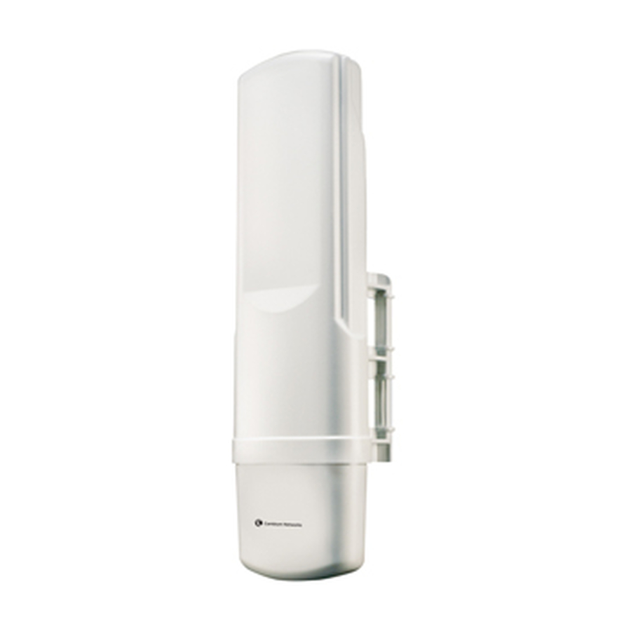
Page 11: Figure 1: Canopy Access Point Module
LED from left to right. LNK: The link LED displays the status of the Ethernet link to the Canopy module. The LED will be constantly lit if there is an Ethernet link present. The LED is colored green. -
Page 12: Figure 2: Front View Of Cluster Management Module, Installed
Ethernet switch Extra fuse sync Ethernet DC power connectors AC power connectors Figure 2: Front view of Cluster Management Module, Installed AP_CMM2 User Manual Page 12 of 49... -
Page 13: Figure 3: Bottom View Of Cluster Management Module, Installed
Earlier units had four openings on the bottom of the Cluster Management Module as shown in the following figure. Currently shipping units have two additional Ethernet cable and GPS sync cable openings, to allow use of thicker, shielded cables. N-connector to GPS antenna GPS sync cables Network feed Power feed... -
Page 14: Background Information On Networking
All Canopy radio products (Subscriber Modules, Access Point Modules, and Backhaul Modules) have the default IP address of 169.254.1.1. For a computer to talk to Canopy, as it comes from the factory, either of the following conditions must be met: •... -
Page 15: System Overview And Site Planning
For more information on the Canopy Backhaul Module see its user manual. The Cluster Management Module is key to the operation of the Canopy System. At one cluster site or throughout the system the Cluster Management Module provides a GPS timing pulse to each module so that their transmission cycles are synchronized. -
Page 16: Site Selection Criteria
Will trees grow into the line-of-sight path? • When possible, avoid high RF energy sites (i.e. AM/FM stations, high powered antennas, etc.) Do not place Canopy equipment in the same plane as other RF equipment. •... -
Page 17: General Considerations
How many Access Point clusters are being planned for deployment? Each cluster will need to use a Cluster Management Module for seamless operation within the entire Canopy System. How many Access Point modules are being planned for each site in the deployment? Access Point modules can be distributed;... -
Page 18: Channel Plans
This is so that in the event of co-location with other equipment the operator can customize the channel layout for interoperability. 5.2 GHz Recommended Frequencies The following are the 3 non-overlapping channels that are recommended by the Canopy team for use with an Access Point cluster: •... -
Page 19: Multiple Access Points Clusters
5.7 GHz Plan Direction of Access Point sector Frequency Sector ID Symbol North – (0°) 5.745 GHz Northeast – (60°) 5.765 GHz Southeast – (120°) 5.785 GHz South – (180°) 5.745 GHz Southwest – (240°) 5.765 GHz Northwest – (300°) 5.785 GHz Multiple Access Points Clusters When deploying multiple Access Point cluster in a given area it is recommended that the clusters... -
Page 20: Networking Information
NETWORKING INFORMATION The Canopy Access Point module will each use an IP address on the operator’s network. It is recommended that the Access Point modules never be placed directly onto the Internet. IP addresses may be assigned sequentially clockwise around an Access Point cluster for easier manageability. -
Page 21: Advanced Features
On the base Canopy system, DES encryption of the over the air link is turned on per Access Point module or Backhaul timing master module. DES encryption does not affect the performance or throughput of the system. -
Page 22: Branding
The Canopy logo file is called canopy.jpg and the replacement file must also be called canopy.jpg . The new file is transferred via FTP to the module and then added to a special filesystem through a telnet session. The following command can be used during a telnet session: •... -
Page 23: Snmp
64336 bytes SNMP Simple Network Management Protocol (SNMP) can be used to monitor the Canopy modules. The standard MIB-II (systems and interfaces) objects are programmed into the modules. For specific information on this MIB see RFC 1213 for details. -
Page 24: Installation
INSTALLATION The following steps are required to install the Canopy Access Point module(s), the Cluster Management Module, and the GPS antenna: • Unpack the Canopy products • Configuration of the Access Point modules • Configuration of the Cluster Management Module •... -
Page 25: Configuration Of The Cluster Management Module
“ , . ‘ { } / \ ; : [ ] ( ) ` ~ NOTE: If the operator forgets either the password or the IP address for the module, a Canopy default plug can be used to regain access. For details, see the section on the default plug under Interface Screens. -
Page 26: Installation Of The Equipment
• Needle-nose pliers When power is applied to a Canopy module or the unit reset via the web-based interface, the module will take approximately 25 seconds to boot up. During this boot up time, power on self- tests and other diagnostics are being performed. -
Page 27: Figure 8: Detail Of Pole Mounting
The modules can be mounted in a variety of locations, choose the best location for your particular application. Modules do not have to mounted directly next to each other, they can be distributed throughout a given site. Mounting can be done by using stainless steel hose clamps or another equivalent fastener. -
Page 28: Figure 9: Detail Of Gps Antenna Mounting
If necessary, route a network cable into the Cluster Management Module and connect to the uplink port on the switch. As with any such installed devices, proper grounding of the Ethernet cable is necessary. The Canopy Surge Suppressor is such a device for this situation. •... -
Page 29: Verification
Replace the base cover on all of the Access Point modules. • Close and lock the Cluster Management Module. All Canopy modules connected to the Cluster Management Module must be configured to “ Sync to Received Signal ”. Otherwise GPS timing pulse will not be transmitted to the modules. -
Page 30: Cabling
When connecting a Canopy device directly to a hub, switch, or router use a RJ-45 crossover cable. When using the Canopy AC wall adapter the +V is +11.5VDC to +30VDC with a nominal value of +24 VDC, and the maximum Ethernet cable run with the AC wall adapter is 328 feet (100 meters). - Page 31 RJ-11 Straight-Thru 1-pps 1-pps pin 1 → white / orange ← pin 1 pin 2 → white / green ← pin 2 pin 3 → white / blue ← pin 3 pin 4 → green ← pin 4 used pin 5 → blue ←...
-
Page 32: The Interface Screens
THE INTERFACE SCREENS The Canopy Access Point module contains a series of web pages that are used to interface to the unit. The following is a quick reference to interface screens. Note: These screens are subject to change by subsequent software versions. To access the web based interface you first must be on a computer that is in some way connected to the Access Point module. -
Page 33: Status Page
• Network IP Address Each of the pages in the Quick Start will explain a little about Canopy and ask the operator for a choice that best addresses the network requirements. At the end, the operator will be given the opportunity to review the configuration selected and save it to non-volatile memory. - Page 34 Radio Slicing Value: displays information to be used be Canopy technical support. Radio Transmit Gain Setting: displays information to be used by Canopy technical support. Site Name: displays information relating to the name of the physical module. This parameter can be set by the operator on the Configuration web page.
-
Page 35: Configuration
CONFIGURATION Figure 13: Configuration web page The Configuration web page contains information and configurable parameters pertaining to the operation of the product. The first line of information on the Configuration screen is a repeat of the Device Type from the Status web page. The following are the parameters and their descriptions. Sync Input: choose the type of synchronization that this Access Point module will use. - Page 36 The default address is 169.254.1.1. If the IP address is forgotten, the operator will need physical access to the module and will need to create a Canopy “default plug”. See steps at the end of this section for use of a default plug.
- Page 37 FTP sessions. If the password is forgotten, the operator will need physical access to the module and will need to create a Canopy “default plug” to override the unit. See steps at end of section for use and creation of a default plug.
- Page 38 FTP session, the user that MUST be used is “root”. If the password is forgotten, the operator will need physical access to the module and will need to create a Canopy “default plug” to override the unit. See steps at end of this section for use of a default plug.
-
Page 39: Canopy Default Plug
Configuration page) back to their factory settings. Reboot: depressing this button will reboot the module. CANOPY DEFAULT PLUG When inserted, the default plug brings the module up with a default configuration. This allows the operator to regain control of a module, which may be using an IP address and/or password that has been forgotten. -
Page 40: Event Log
EVENT LOG This page contains information that is recorded from the subscriber module for troubleshooting purposes. Please make note of the information that is gathered here when calling for technical support. Clear Event Log: this button will clear the event log. LUID SELECT Figure 14: LUID Select web page This web page makes is possible for the operator to view the web pages of registered subscriber... -
Page 41: Link Test
If the web page is not set to automatically refresh, click the “ Refresh Display ” button to see the results. For a Canopy System link to be considered acceptable it is necessary for the efficiencies of the link test to be greater than 90% in both the uplink and downlink direction. -
Page 42: Sessions
Average RSSI: 1842, Last RSSI: 1873 Average Jitter: 6, Last Jitter: 5 Descriptions of the parameters that are useful for managing and troubleshooting a Canopy System are: LUID: displays the logical unit ID of the subscriber module. As each subscriber module registers to the Access Point module it is assigned a LUID. - Page 43 compared to other subscriber modules registered with this Access Point, there may be an issue with the installation of the subscriber. Average RSSI: displays the average RSSI value for the subscriber module. Last RSSI: displays the last RSSI value for the subscriber module. Average Jitter: displays the average Jitter value for the subscriber module.
-
Page 44: Gps Status
GPS STATUS The GPS Status web page displays information about satellites seen and tracked when the Access Point module is configured to “ sync to the received signal” and is connected to a Cluster Management Module. ETHERNET STATS The Packet Stats web page reports TCP throughput and error information for the Ethernet connection of the subscriber module. -
Page 45: Expanded Stats
EXPANDED STATS Clicking on the Expanded Stats link will display a number of pages of statistics that are maintained by the Canopy module. Canopy Technical Support may ask the operator for specific information in this section when troubleshooting an issue. -
Page 46: Accessories
ACCESSORIES The following accessories are available for use with the Canopy System. To purchase accessories, please contact an authorized Canopy dealer, unless otherwise noted. • Universal mounting bracket • Passive reflector dishes for use with 5.7 GHz subscriber modules. •... -
Page 47: Appendix
APPENDIX There are two basic concepts that are needed for a basic understanding of networking, IP addresses and subnet masks. IP addresses are 32-bit binary numbers that have two corresponding parts or sub-addresses, the first part identifying the network and the second part identifying the hosts on the network. -
Page 48: Specifications
0.3A @ 24 VDC (7.2 watts) Interface 10/100 BaseT, half/full duplex Rate auto negotiated (802.3 compliant) Protocols Used by CANOPY IPV4, UDP, TCP, ICMP, Telnet, HTTP, FTP, SNMP, DES Protocols Supported by Canopy Switched Layer 2 Transport with support for all common Ethernet protocols including IPV6, NetBIOS, DHCP, IPX, etc. -
Page 49: Ap_Cmm2 User Manual
CLUSTER MANAGEMENT MODULE GEN II PHYSICAL Max length from Cluster Management Module 328 cable feet (100 meters) to any radio Max length from Cluster Management Module 100 cable feet (30.5 meters) to GPS antenna 17.00” H x 12.88” W x 6.50” D Dimensions (43.18 cm H x 32.72 cm W x 16.51 cm D) Weight...