Advertisement
Quick Links
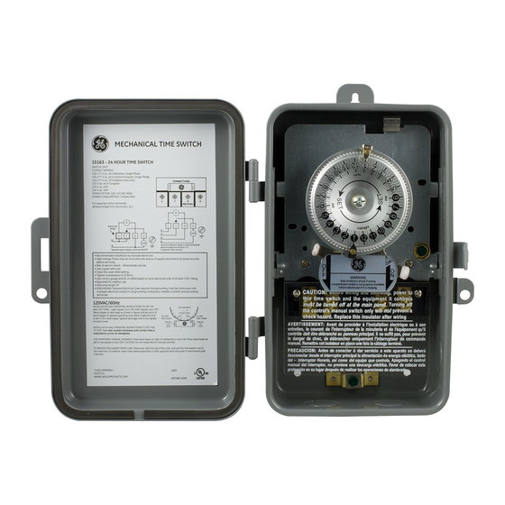
Quick Start Guide
Commonly used tools
- Phillips head screwdriver
- Flat head screwdriver
- Hammer
- Wire cutter/stripper
MIN. COPPER WIRE
SIZE (AWG)
14
12
10
8
• RECOMMENDED INSTALLATION BY LICENSED ELECTRICIAN.
• HIGH VOLTAGE (THERE MAY BE MORE THAT ONE SOURCE OF SUPPLY)
DISCONNECT ALL POWER SOURCES BEFORE SERVICING.
• RISK OF ELECTRIC SHOCK – ALL TERMINALS ARE LIVE.
• USE COPPER WIRE ONLY.
• CLOSE THE COVER AFTER SETTING.
• TIGHTEN CONNECTIONS TO 25 LBF-IN.
• USE CORRECT GAUGE WIRE (8-14 AWG) BASED ON LOCAL ELECTRICAL
CODE OF AT LEAST 105C RATING.
• APPROVED FOR OUTDOOR USE.
• WIRE STRIP LENGTH ½"
• GROUNDING: NATIONAL ELECTRICAL CODE REQUIRES THAT GROUNDING
MUST BE CONTINUOUS AND IN PROPER ELECTRICAL CONTACT IN ALL
GROUNDING CONDUCTORS, METALLIC CONDUITS AND GROUNDING
TERMINALS.
Supplied hardware
- #10 Screw (3)
- #10 Drywall anchors
MAX LOAD
MINIMUM INSULATION
(AMP)
15
20
30
40
USE CORRECT GAUGE WIRE PER LOCAL ELECTRICAL CODE
WARNING
TEMP (°C)
60
60
60
105
PRESSURE PLATE
TERMINAL SCREW
MAKE SURE WIRE
INSULATION CLEARS
PRESSURE PLATE
Advertisement

Related Manuals for GE 15163


Summary of Contents for GE 15163
- Page 1 Quick Start Guide Commonly used tools Supplied hardware - Phillips head screwdriver - #10 Screw (3) - Flat head screwdriver - #10 Drywall anchors - Hammer - Wire cutter/stripper MIN. COPPER WIRE MAX LOAD MINIMUM INSULATION SIZE (AWG) (AMP) TEMP (°C) PRESSURE PLATE TERMINAL SCREW MAKE SURE WIRE...
- Page 2 Knockouts Each metal box comes with ½” and ¾” knockouts. Follow the pictures below to remove knockouts. For ½” knockout, place small blade screw driver as pictured above. Tap lightly to punch knockout loose. For ¾” knockout, first use screwdriver to punchout ½” knockout then use pliers to remove outer ring.
-
Page 3: Mounting The Timer
Mounting the timer 1. Select the location for the timer and use the three holes provided for mounting. Mounting holes 2. Remove module from timer box. Hold the timer box in place and mark the holes on the mounting surface. 3. - Page 4 120 VAC Setup: Single 120 VAC Load GROUND Removable Bridge GROUND LOAD Typical for same voltage in LOAD and MOTOR Connections: L- Line Input to Timer Motor 1-Line Input to Switch X-Neutral Input to Timer Motor 2-Line Output of Switch WARNING •...
- Page 5 Step 1: Remove Plastic Guard Remove screws using a Phillips Head screwdriver and keep them to the side. Carefully remove plastic guard and also keep to the side. Step 2: Connect the Input/Clock Motor Voltage 1. Connect 120VAC Hot (Black) to Terminal L. Do not remove the jumper connecting Terminals “L”...
- Page 6 Step 3: Complete the circuit to the load 1. Connect 120VAC Hot (Black) of the LOAD to Terminal 2. 2. Connect 120VAC Neutral of the Load (White) to terminal X. 3. Connect the bare wire to the ground lug. Tighten the screw terminals to 25in-lb.
- Page 7 Step 5: Activate Timer 1. Turn the mechanism dial counter clockwise to set the current time as accurately as possible. 2. After wiring and setting the timer with the ON/OFF trippers in the correct timer positions. Be sure to depress the ON or OFF lever to set the timer to the desired state.
- Page 8 It snaps easily in and out of place. If the guard has come off during shipment or installation, reinstall by placing the two tabs at the bottom in the appropriate slots. Ends fit into these holes Plastic guard fitted correctly 15163 VERSION 2 01/13/16 WWW.JASCOPRODUCTS.COM...