Advertisement
Quick Links
Digital Time Switch
SPECIFICATIONS
Input Voltage: 120 VAC, 208/240 VAC, or 277 VAC in all units based
upon dipswitch configuration.
Switch Rating: DPDT Models
Normally Open Contacts
40A Resistive, 120-277Vac.
30A General Purpose, 120-277Vac.
20A Resistive, 30Vdc
1 HP, 120Vac ; 2HP, 240Vac ;
20A Ballast, 120-277Vac.
15A Tungsten, 120Vac
5.4A Tungsten, 208-277Vac.
800VA, Pilot Duty, 120Vac.
720VA, Pilot Duty, 240-277Vac.
TV-5, 120Vac
Normally Closed Contacts
30A Resistive, 120-277Vac
15A General Purpose, 120-277Vac
15A Resistive, 30Vdc
20A Ballast, 120-277Vac
1/4HP, 120Vac; 1/2HP, 208-240Vac.
290VA, Pilot, 120Vac.
360VA, Pilot, 208-240Vac.
NOTE: If loads are connected to both NC and NO contacts, both contacts are
derated to 67% of the above values.
ENVIRONMENTAL RATINGS
Ambient Temperature: –40F to 130F
Humidity: 0-95% RH, Non-condensing
WIRING CONNECTIONS
Screw clamp terminals for up to 2, 8 AWG wires per position. For supply
connections, use 8AWG or larger wires suitable for at least 105° C. Use copper
conductors only.
Lights
Power LED (Orange)
– Light illuminates when power is applied to
the timer
Status LED (Green)
– Light illuminates when power is applied to load.
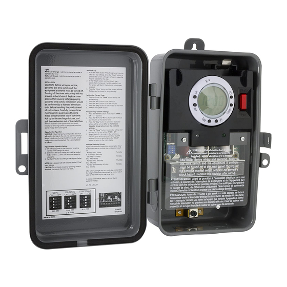
INSTALLATION
CAUTION: Before wiring or service, power to this time switch and the
equipment it controls must be turned off. Turning off the timer switch
only will not prevent a shock hazard. Replace cover plate within housing
before supplying power to time switch. Installation should be performed
by a licensed electrician only. Before installing this product, read all
instructions carefully. Remove protective cover panel within time-switch
housing by removing screws located below timer face.
Dipswitch Configuration
WARNING:
Failure to properly configure the dipswitch will result in
damage to the unit and void the warranty! Before installing and wiring the GE
Time Switch, proper configuration must be selected. This is accomplished as
follows:
120VAC
208~240VAC
ON
OFF
ON
OFF
ALL ON
1 & 4 OFF
2 & 3 ON
NOTE: For outdoor locations, rain-tight or wet-location conduit hubs that
comply with requirements of UL 514B (standard for fittings for conduit and
outlet boxes) must be used.
1.
To mount the box, remove the timer mechanism. Push the latch at the
top of the timer mechanism. The mechanism will release and pull out of
box.
2.
Select knockouts to be used. Remove the inner 1/2" knockout by
inserting a screwdriver in the slot and carefully punch knockout loose.
Remove slug. If the 3/4" knockout is required, remove the outer ring
with pliers after removing the 1/2" knockout. Smooth edges with file if
necessary.
3.
Place enclosure in desired mounting location and mark the three
mounting holes.
4.
Drill holes for #8 screws using 1/8" drill bit, start screws in holes.
5.
Place enclosure over screws and tighten screws.
6.
Connect conduit hubs to conduit before connecting the hubs to the
enclosure. After inserting hubs into enclosure, carefully tighten hub lock
nut. Do not over-tighten.
7.
Install in accordance with all applicable national and local code
requirements. See Figure 1 and wiring diagrams.
8.
To place the timer mechanism back in the metal box timer first hold top
of the timer mechanism. Slide the plastic case into the metal box latches
in the center of the metal box. Push the top of the timer mechanism until
the metal latch snaps into place.
GROUNDING: This enclosure has a grounding block on the bottom/
inside of the timer box. Screw in all ground wires to the ground block.
A pool application does not require bonding.
This enclosure does not provide grounding between conduits. When using
non-metallic conduit or cable, connect the ground wires of all cables together
with a wire nut. When metallic conduit is used, use grounding-type bushings
and a jumper wire between each conduit.
277VAC (Default)
ON
OFF
ALL OFF
15136
Advertisement

Related Manuals for GE 15136


Summary of Contents for GE 15136
- Page 1 Failure to properly configure the dipswitch will result in upon dipswitch configuration. damage to the unit and void the warranty! Before installing and wiring the GE Time Switch, proper configuration must be selected. This is accomplished as Switch Rating: DPDT Models...
-
Page 2: Operating Instructions
4. Press the “Day” button to set the day of the week. After setting a single day or a multi-day-combination the programmed timer 5. Release the “Clock” button. settings will be carried out on each of the week-days at the same time. 15136... - Page 3 2. To turn the random feature off repeat step 1. MADE IN CHINA / HECHO EN CHINA GE is a trademark of General Electric Company and is under license by Jasco Products Company LLC, 10 E. Memorial Rd., Oklahoma City, OK 73114.