Table of Contents
Advertisement
Quick Links
Библиотека СОК
1. SAFETY SUMMARY
DANGER:
DO NOT pour water into the remote controller
-
(hereafter called "controller"). These products are
equipped with electrical parts. If poured, it will cause a
serious electrical shock.
DO NOT operate switches by wet hand. It may cause
-
an electrical shock.
In case that the protective devices often function or
-
the operation switches do not function well, turn OFF
the main power supply and contact your service
contractor of HITACHI.
In case that other abnormalities are found, stop the
-
system, turn OFF the main power supply and contact
your service contractor of HITACHI.
2. INSTALLATION WORK
2.1. SELECTION OF INSTALLATION PLACE
Location of Remote Controller
Select a suitable place for handling and determine the
installation place of the controller with the customer's
acceptance.
Especially in case that a remote control thermistor (C8)
is used, pay attention to select the installation place.
2.2. BEFORE INSTALLATION
Check the contents and the number of the
accessories in the packing.
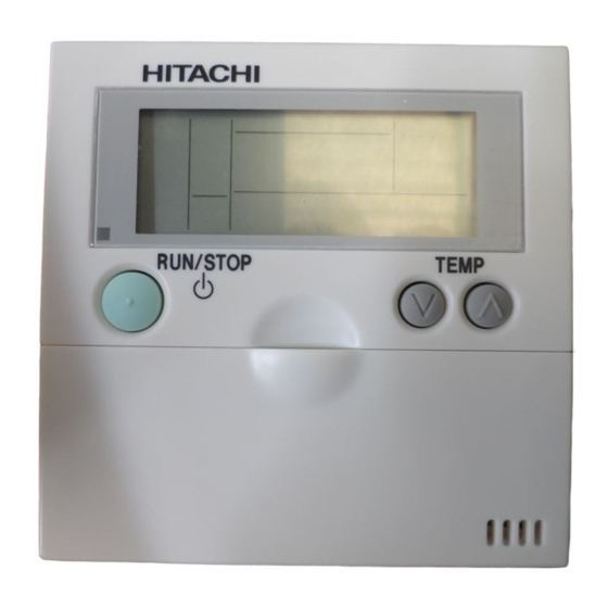
Remote Control
Switch, for Operation
Control
2.4. INSTALLATION PROCEDURE
1. Insert the edge of the flat head screwdriver into the dent parts at the bottom of the holding bracket, push and turn the
screwdriver and remove the controller from the holding bracket as shown in the next figure.
Dent
Part
2. Attach the controller to the holding bracket as follows.
INSTALLATION MANUAL FOR PC-P2HTE
2 screws
1 Band.
M4x16L For
For fixing
fixing the
Cable to Ring
Holding Bracket
Core
onto the wall
Controller
Dent Part
Holding
Bracket
Screwdriver
INSTALATION AND OPERATION MANUAL FOR PC-P2HTE
WARNING:
DO NOT perform installation work and electrical wiring
-
connection by yourself.
In case that a service work such as repair,
maintenance, etc. is required, contact your service
contractor of HITACHI.
DO NOT modify the electrical wiring. It may cause
-
serious accidents.
NOTE:
For one remote controller, the maximum total length
of the cable (including the signal wire between units)
is 30 m when using 0.3 mm² cable and 500 m when
using the cable thicker than 0.75 mm².
2.3. INSTALLATION SPACE
In case of installing the controllers in vertical line, keep a
distance more than 50 mm between the controllers
vertically. If the distance is insufficient, the front cover of
the controller can not open wide enough
Ring
Core.
Bottom view
Dent part
Screwdriver
Holding
Bracket
More than
50 mm
Holding Bracket
Dent part
1
Advertisement
Table of Contents

Related Manuals for Hitachi PC-P2HTE


Summary of Contents for Hitachi PC-P2HTE
- Page 1 Библиотека СОК INSTALATION AND OPERATION MANUAL FOR PC-P2HTE INSTALLATION MANUAL FOR PC-P2HTE 1. SAFETY SUMMARY DANGER: WARNING: DO NOT pour water into the remote controller DO NOT perform installation work and electrical wiring (hereafter called “controller”). These products are connection by yourself.
-
Page 2: Electrical Wiring
INSTALATION AND OPERATION MANUAL FOR PC-P2HTE In case of exposing Remote Control Cable. 2. Attach the stopper to the cable at the inside of the draw-out hole. Fix the holding bracket onto the wall as shown below Band (Field- Cable... -
Page 3: Checking Procedures
INSTALATION AND OPERATION MANUAL FOR PC-P2HTE Address of Indoor Units: Main unit unit unit unit CAUTION: Use the twist (shield) pair cable (2 x 0.75mm²) as transmitting wire cable for prevention of the malfunction (The total cable length is max. 500m). -
Page 4: Selection Of Indoor Unit
INSTALATION AND OPERATION MANUAL FOR PC-P2HTE 5.2. SELECTION OF INDOOR UNIT Selection of Indoor Unit for Optional Setting “01” stop flickers. Select the indoor unit to set by pressing the “” or “” switch HIGH and press the “OK” switch. - Page 5 INSTALATION AND OPERATION MANUAL FOR PC-P2HTE Optional Setting Items (Cont.) Individual Items Setting (B) Setting Conditions Code Availability 00: Not Available Remote Control Thermostat 01, 02: *3) Not Prepared Not Used Not Prepared Not Used 00: A Contact Selection of Manual Stoppage Logic...
- Page 6 INSTALATION AND OPERATION MANUAL FOR PC-P2HTE 5.3.2. INPUT/OUTPUT NUMBER Input/Output Setting Mode (Mode Number “02”) Selection of Input/Output Number Input/Output Number HIGH COOL Select the input/output SERVi C E number by pressing the “SELECT” switch. ...
-
Page 7: Setting Timer (Programming)
INSTALATION AND OPERATION MANUAL FOR PC-P2HTE 6.2. SETTING TIMER (PROGRAMMING) 5.Press SELECT △▽ switch 1.Press TIMER switch. SET to adjust “minutes”, and and SCHEDULE are when adjusted, press OK indicated. Schedule Number switch. “Minutes” is “1” flickers and other indicated and “hour” of numbers are indicated. - Page 8 INSTALATION AND OPERATION MANUAL FOR PC-P2HTE 6.5. SETTING OF SHIFT TEMPERATURE (ENERGY SAVING MODE) Increase or decrease setting temperature (±3 ºC or ±5 ºC) according to in ON time or OFF time. shift of temperature differs based on the operation mode. In case of “fan”, “cooling” and “dry”, from the shifting temperature: + shift. In case of “heating”, from the setting temperature: - shift.