Table of Contents
Advertisement
Quick Links
Advertisement
Table of Contents

Related Manuals for Honeywell BendixKing KLR 10


Summary of Contents for Honeywell BendixKing KLR 10
- Page 1 KLR 10 Lift Reserve Indicator Installation Manual BendixKing.com...
- Page 2 Manual, the information in the Airplane Flight Manual shall take precedence. COPYRIGHT NOTICE © 2013 Bendix/King by Honeywell. All rights reserved. Reproduction of this publication or any portion thereof by any means without the express written permission of Honeywell International Inc. is prohibited. See Appendix for complete terms and conditions.
- Page 3 KLR 10 Lift Reserve Indicator Installation Manual KLR 10 ™ LIFT RESERVE INDICATOR INSTALLATION MANUAL The KLR 10 is approved for installation in experimental category aircraft ONLY. It is not approved for installation in certified aircraft P/N D201305000058 Title Rev 1 Jul 2013 Page T-1...
- Page 4 KLR 10 Lift Reserve Indicator Installation Manual This Page Intentionally Left Blank Title P/N D201305000058 Page T-2 Rev 1 Jul 2013...
- Page 5 KLR 10 Lift Reserve Indicator Installation Manual Revision History and Instructions Manual KLR 10 Life Reserve Indicator Installation Manual Revision Summary Revised footers. Manual KLR 10 Life Reserve Indicator Installation Manual Revision Summary This is a new release. P/N D201305000058 Record of Revisions Rev 1 Jul 2013 Page RR-1...
- Page 6 KLR 10 Lift Reserve Indicator Installation Manual Record of Revisions REVISION REVISION NUMBER DATE JULY, 2013 JULY, 2013 Record of Revisions P/N D201305000058 Page T-2 Rev 1 Jul 2013...
-
Page 7: Table Of Contents
KLR 10 Installation Manual Table of Contents Section Page 1. GENERAL ............................1-1 Objective: ........................... 1-1 References: ..........................1-1 Page and Subject Numbers: ...................... 1-1 Revisions: ........................... 1-1 Technical Support: ........................1-1 Warranty Information: ......................... 1-1 Standard Components ....................... 1-3 Optional Components ........................ - Page 8 Acronyms and Abbreviations ...................... 5-1 IF Module Connectors Pin Definitions ..................5-2 AOA Probe Angles........................5-3 Positive Probe Lock System ....................... 5-3 Limitations ........................... 5-4 Honeywell-Confidential ....................... 5-5 Copyright - Notice ........................5-6 Table of Contents P/N D201305000058 Page TC-2...
- Page 9 KLR 10 Installation Manual List of Illustrations Figure Page Figure 1-1: KLR 10 Indicator ........................1-4 Figure 1-2: Panel Mounting Kit ........................1-4 Figure 1-3: KLR 10 Swivel Mount ......................1-5 Figure 1-4: KLR 10 Interface ........................1-5 Figure 1-5: AOA Probe Sensor Fittings ..................... 1-6 Figure 1-6: Mounting Plate ........................
- Page 10 KLR 10 Installation Manual List of Tables Table Page Table 1-1: Standard Kits ..........................1-3 Table 1-2: KLR 10 Standard Kit Components .................... 1-3 Table 1-3: KLR 10 Optional Components ....................1-3 Table 4-1: Indications and Annunciations During Calibration ..............4-9 Table 5-1: Power Connector ........................
-
Page 11: General
KLR 10 Installation Manual GENERAL OBJECTIVE: This manual contains a lot of information that is repeated and shown in different ways to help explain all steps of installation through calibration and help with the FAA required paperwork. Think of this manual as a written journey, to give you as much detail as you want. - Page 12 Seller for use in Seller-manufactured Products; (6) products not manufactured by Honeywell (but manufacturer’s warranty is passed through to Buyer to the extent permitted); or (7) Products normally consumed in operation or which have a normal life inherently shorter than the foregoing warranty period including, but not limited to, consumables (e.g.
-
Page 13: Standard Components
KLR 10 Installation Manual STANDARD COMPONENTS The table below shows the list of standard components for the KLR 10 kit: Table 1-1: Standard Kit PART NUMBER DESCRIPTION 89000008-001001 Standard Kit Table 1-2: KLR 10 Standard Kit Components DESCRIPTION KLR 10 Indicator 6 ft Display Cable KLR 10 Flush Mount Panel Kit KLR 10 Interface Module... -
Page 14: Klr 10 Main Component Details
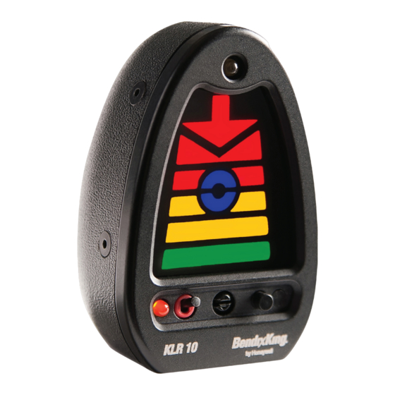
KLR 10 Installation Manual KLR 10 MAIN COMPONENT DETAILS: KLR 10 indicator The KLR 10 indicator is 2.35 in. tall X 1.55 in. wide X 1.26 in. deep and can be mounted anywhere in the cockpit Figure 1-1: KLR 10 Indicator Panel Mounting Kit Mounting ears are included in the Panel Mounting Kit that attach to either side of the KLR 10 Indicator as shown in the figure below. -
Page 15: Klr 10 Swivel Mount Kit
KLR 10 Installation Manual KLR 10 Swivel Mount Kit An optional mounting kit is available for vertical swivel flush mount for those aircraft that have a sloping glare shield, see Figure 1-3 below. Figure 1-3: KLR 10 Swivel Mount KLR 10 Interface Module (IF Module) The IF module is 1.63 in. -
Page 16: Klr 10 Aoa Probe
KLR 10 Installation Manual Figure 1-5: AOA Probe Sensor Fittings KLR 10 AOA probe The AOA Probe is mounted on a 9 in. x 9 in. mounting plate. The mounting plate is cut to fit the existing opening. Figure 1-6: Mounting Plate AOA Probe and 2 fittings = .23 lbs. -
Page 17: Planning
KLR 10 Installation Manual PLANNING PREPARATION: This chapter will guide you through the planning phase of the installation process. To prepare for the installation it is recommended that you read this manual in its entirety and complete this chapter prior to performing any work. -
Page 18: Establish The Location For The If Module
KLR 10 Installation Manual IF you plan to install the KLR 10 indicator on a glare shield you will need to make a determination that the structure is strong enough to support the weight of the indicator. This is also a preferred method of installing the KLR 10 indicator and in most cases will require no additional support structure. -
Page 19: Establish The Location For The Aoa Probe
KLR 10 Installation Manual ESTABLISH THE LOCATION FOR THE AOA PROBE The AOA probe is mounted on the wing with the following limitations: The AOA probe is mounted a minimum of 24 in. outboard of the propeller arc. The AOA probe is a mounted a minimum of 12 in. -
Page 20: Establish A Plan To Route The Sense Lines
KLR 10 Installation Manual ESTABLISH A PLAN TO ROUTE THE SENSE LINES The sense lines must be installed through the aircraft structure with the following limitations: Do not remove hose end caps until final connector installation. This keeps contamination from entering the sense lines during installation. -
Page 21: Review Your Plans
KLR 10 Installation Manual REVIEW YOUR PLANS Make sure that your plans meet the requirements of the following regulations: §23.1301: (a) Is it of a kind and design appropriate to its intended function? If you intended to add a KLR 10 and can do it as described above than the answer is yes. (b) Can it be labeled as to its identification, function? The indicator meets this identification requirement for the indicator. - Page 22 KLR 10 Installation Manual This Page Intentionally Left Blank Planning P/N D201305000058 Page 2-6 Rev 1 Jul 2013...
-
Page 23: Installation
KLR 10 Installation Manual INSTALLATION INSTALLATION OF THE PROBE MOUNTING PLATE In chapter two the location for the AOA probe was established. If it was determined that additional structure or modification to the wing will be required, perform that work now in accordance with the established plan and or any required engineering data. -
Page 24: Install Wiring, Switch & Circuit Breaker For Klr 10
KLR 10 Installation Manual Do not clamp sense lines at the end fittings. Use AN931 grommets (preferred) or bulkhead fittings where the sense lines pass thru bulkheads. Do not remove the caps installed on either ends of the sense lines and leave sufficient length so they may be cut to length later in the installation process. - Page 25 KLR 10 Installation Manual In chapter two a plan was established so that the requirements for installing the heated probe were satisfied, in accordance with that plan: If not already done, ensure that the aircraft electrical system is NOT powered and the aircraft battery is disconnected.
-
Page 26: Install The Klr 10 Swivel Mount (Optional)
KLR 10 Installation Manual INSTALL THE KLR 10 SWIVEL MOUNT (OPTIONAL) The “KLR 10” Indicator can be mounted in the pilot’s peripheral vision, vertically by purchasing the optional mounting kit. This mounting kit allows for accurate positioning in a vertical orientation, on or above the aircrafts glare shield and mounts simply with 4 screws. - Page 27 KLR 10 Installation Manual Figure 3-4: Swivel Mount Instructions - Step 1 Step 2 - When disk is in the final position, use a #40 drill to: Drill hole 2 and cleco thru hole 2. Drill hole 3 and cleco thru hole 3. ...
-
Page 28: Installation Of The Klr 10 Indicator
KLR 10 Installation Manual Step 5 - Mount the swivel base to the glareshield using the provided 4-40 mounting screws and nuts. INSTALLATION OF THE KLR 10 INDICATOR In chapter two the location for the KLR 10 indicator was established. If it was determined that additional structure or modification to the instrument panel will be required, perform that work now in accordance with the established plan and or any required engineering data. -
Page 29: Figure 3-7: Klr 10 Interface Module Electrical Connectors
KLR 10 Installation Manual Figure 3-7: KLR 10 Interface Module Electrical Connectors Figure 3-8: KLR 10 Interface Module Sense Line Connectors Connect the display cable connector (10 Pin) to the IF module connector, they are both color coded BLUE. This may be accomplished by holding the cable connector by its black strain relief and rotate it on the display connector until the alignment keyways mate up then push towards the control module and the retaining collar will snap into place tightly against the IF module. -
Page 30: Installation Of Aoa Probe
KLR 10 Installation Manual INSTALLATION OF AOA PROBE (Optional), if installing a heated probe, it will come from the factory installed with high temperature fittings and colored (Blue / White) high temperature hoses with the heater in AOA probe. Install the AOA probe in the mounting plate and secure it as follows: ... -
Page 31: Figure 3-11: Correct Position Of Probe Lock Plate
KLR 10 Installation Manual Probe Lock Plate Forward Figure 3-11: Correct position of Probe lock plate NOTE: The probe lock plate can face forwards or backwards and can be placed on either the left or right side of the AOA probe depending on which pin hole is selected on the AOA probe. ... -
Page 32: Inspect The Klr 10 Installation
KLR 10 Installation Manual BLUE WHITE LINE LINE Figure 3-13: AOA Probe Connectors Ensure the lines are installed correctly by giving the line a light pull and if the line does not back out it is a good connection. If you ever need to disconnect the lines depress the black collar (the furthest outboard portion of the connector) on the fitting and pull the line out. -
Page 33: Setup And Calibration
KLR 10 Installation Manual SETUP AND CALIBRATION The initial setup and calibration of the KLR 10 has 7 simple steps: 1. On ground Zero Pressure calibration, see page 4-1. 2. Set initial Brightness calibration of the KLR 10 Indicator, see page 4-2. 3. -
Page 34: Set Brightness Of The Klr 10 Indicator (Optional)
KLR 10 Installation Manual NOTE: This is a Power-On Procedure. For calibration, the system samples power and outputs to gain accuracy. Blue segments on the KLR 10 indicator may flash several times before the electronics stabilize and stop flashing for an acceptable / valid zero pressure point. -
Page 35: Master Volume Set
KLR 10 Installation Manual MASTER VOLUME SET The master volume for the KLR 10 is controlled from the IF Module. Figure 4-1: Master Volume Controls Push the UP recessed button on the IF Module to increase the master volume to your audio panel/intercom/radio. - Page 36 KLR 10 Installation Manual NOTE: While KLR 10 in-flight calibration can be accomplished by a solo pilot, it is advisable that the pilot flying focuses on safely and correctly achieving the calibration set points while a second person assists in performing the indicator calibration. •...
-
Page 37: In-Flight Optimum Alpha Angle (Oaa) Calibration
KLR 10 Installation Manual IN-FLIGHT OPTIMUM ALPHA ANGLE (OAA) CALIBRATION Enter the OAA Calibration Mode as follows: Turn the Calibration Mode Switch so that the slot is vertical. • Press the Brightness button. • segment on the KLR 10 indicator flashes three times, and the unit announces “Calibration Mode On”. -
Page 38: In-Flight Cruise Set Point Calibration
KLR 10 Installation Manual If the Set Point is NOT Successfully entered: • The KLR 10 indicator returns to an inactive state, discards the attempted set point (Values out of range). • • If the AOA probe angle is too low, the KLR 10 indicator’s flashes three times and announces “Invalid Set Point”. -
Page 39: Exiting The Calibration Mode
KLR 10 Installation Manual • The KLR 10 indicator’s “ ” segment flashes three times and announces “Invalid Set Point”. Repeat the In-Flight Cruise Set Point procedure until a valid Set Point is entered. !NEXT STEP MUST BE COMPLETED! EXITING THE CALIBRATION MODE NOTE 1: Both OAA and Cruise set points must be entered and must be valid values before exiting from the calibration mode. -
Page 40: Completing The Calibration
KLR 10 Installation Manual COMPLETING THE CALIBRATION: Confirm the angle of the AOA probe and write it down. Remove the probe assembly from the aircraft. Tighten the AOA probe mounting bolt to 60 ± 10 inch pounds. ... -
Page 41: Table 4-1: Indications And Annunciations During Calibration
KLR 10 Installation Manual Table 4-1: Indications and Annunciations During Calibration INDICATION/ANNOUNCEMENT MEANING All Segments flash continuously and unit The system’s Zero Offset set point is NOT accepted. announces: “Invalid Set Point”. The system’s Zero Offset set point is The unit announces: “Initial Zero Calibration accepted. -
Page 42: Figure 4-2: Oaa Setpoint Flowchart
KLR 10 Installation Manual In-Flight calibration requires the pilot to climb to a safe STEP 1 altitude for slow flight maneuvers. The pilot will fly the aircraft to the condition of Optimum Alpha Angle (OAA): OPTIMUM ALPHA ANGLE Aircraft is at the Optimum Alpha Angle (OAA), when: (IN- FLIGHT CALIBRATION) 1. -
Page 43: Figure 4-3: Cruise Setpoint Flowchart
KLR 10 Installation Manual The pilot must fly the aircraft at a “Cruise” In- Step 2 flight condition, straight and level, holding CRUISE SETPOINT altitude at Cruise power. This procedure sets (IN- FLIGHT CALIBRATION) the display to indicate “Cruise” AOA for the aircraft. - Page 44 KLR 10 Installation Manual This Page Intentionally Left Blank Setup and Calibration P/N D201305000058 Page 4-12 Rev 1 Jul 2013...
-
Page 45: Appendix
KLR 10 Installation Manual APPENDIX ACRONYMS AND ABBREVIATIONS Acronyms and abbreviations used in this manual are defined as follows: TERMS DEFINITION Advisory Circular Angle of Attack Coefficient of Lift Code of Federal Regulations CLmax Coefficient of Lift Maximum Coefficient of Drag Coefficient of Lift over Coefficient of Drag Federal Aviation Administration Federal Air Regulations... -
Page 46: If Module Connectors Pin Definitions
KLR 10 Installation Manual IF MODULE CONNECTORS PIN DEFINITIONS Table 5-1: Power Connector DEFINITION +12 VDC to +28 VDC Input Power Ground Metal Ground Not Connected Table 5-2: Auxiliary I/O Connector DEFINITION AP Ground AP Audio (mono) Reserved Shield 5-15 Not Connected Table 5-3: Display Connector DEFINITION... -
Page 47: Aoa Probe Angles
KLR 10 Installation Manual AOA PROBE ANGLES Positive Probe Lock System The design of the AOA probe and the mounting plate allows for the probe lock plate to positively pin the AOA probe from any possible movement after final assembly. Due to differences in wing designs and the number of wing mounting locations, it may become necessary to change the AOA probe angle to allow for full scale and accurate electronic calibration. -
Page 48: Limitations
KLR 10 Installation Manual LIMITATIONS Operating Airspeed Minimum 35 knots TAS Range: Maximum 500 knots TAS Operating Altitude Minimum 0 Ft MSL Range: Maximum 30,000 Ft MSL Operating Humidity: Maximum 96% Relative Humidity Operating Minimum -20°C (-4°F) Temperature Range: Maximum 66°C (151°F) Storage Minimum -30°C (-22°F) Temperature Range:... -
Page 49: Honeywell-Confidential
Materials and you provide prior written notice to Honeywell. 2. Rights In Materials - Honeywell retains all rights in these Materials and in any copies thereof that are not expressly granted to you, including all rights in patents, copyrights, trademarks, and trade secrets. No license to use any Honeywell trademarks or patents is granted under this License Agreement. -
Page 50: Copyright - Notice
State of New York without regard to the conflicts of laws provisions thereof. This license sets forth the entire agreement between you and Honeywell and may only be modified by a writing duly executed by the duly authorized representatives of the parties.