Table of Contents
Advertisement
Quick Links
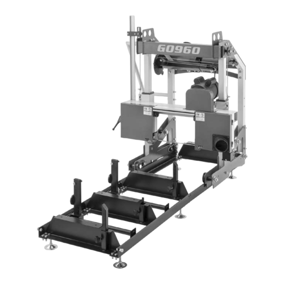
MODEL G0960
MINI SAWMILL PRO
OWNER'S MANUAL
(For models manufactured since 09/22)
COPYRIGHT © OCTOBER, 2022 BY GRIZZLY INDUSTRIAL, INC.
WARNING: NO PORTION OF THIS MANUAL MAY BE REPRODUCED IN ANY SHAPE
OR FORM WITHOUT THE WRITTEN APPROVAL OF GRIZZLY INDUSTRIAL, INC.
#CSLW22408 PRINTED IN TAIWAN
V1.10.22
***Keep for Future Reference***
Advertisement
Table of Contents

Related Manuals for Grizzly G0960


Summary of Contents for Grizzly G0960
- Page 1 (For models manufactured since 09/22) COPYRIGHT © OCTOBER, 2022 BY GRIZZLY INDUSTRIAL, INC. WARNING: NO PORTION OF THIS MANUAL MAY BE REPRODUCED IN ANY SHAPE OR FORM WITHOUT THE WRITTEN APPROVAL OF GRIZZLY INDUSTRIAL, INC. #CSLW22408 PRINTED IN TAIWAN V1.10.22...
- Page 2 This manual provides critical safety instructions on the proper setup, operation, maintenance, and service of this machine/tool. Save this document, refer to it often, and use it to instruct other operators. Failure to read, understand and follow the instructions in this manual may result in fire or serious personal injury—including amputation, electrocution, or death.
-
Page 3: Table Of Contents
Table of Contents INTRODUCTION ..........2 SECTION 5: ACCESSORIES ......48 Contact Info............ 2 SECTION 6: MAINTENANCE ......51 Manual Accuracy ........... 2 Schedule ............51 Identification ........... 3 Cleaning ............51 Controls & Components ......... 4 Lubrication ........... 51 Glossary Of Terms ......... -
Page 4: Introduction
ID label (see below). This information is required for us to provide proper tech support, and it helps us determine if updated documentation is available for your machine. Manufacture Date Serial Number Model G0960 (Mfd. Since 09/22) -
Page 5: Identification
ON/OFF Switch w/Disabling Key Blade Height Scale Push Handle Blade Height Controls Blade Tracking Knob Carriage Log Bunk Blade Tension Lever Dust Blade Cover Port Clamp Track Adjustable Support Foot Model G0960 (Mfd. Since 09/22) -
Page 6: Controls & Components
OFF when pressed in. When key is removed, blade height during operation. button is disabled and machine cannot start. E. Log Bunk (1 of 4): Supports log. Push Handle: Moves carriage along track. Model G0960 (Mfd. Since 09/22) - Page 7 ON/OFF switch in, wait a few minutes for machine to cool, then press reset button. If N. Blade Guide (1 of 2): Supports blade. button does not stay depressed, allow motor to cool longer, then try again. Model G0960 (Mfd. Since 09/22)
-
Page 8: Glossary Of Terms
The following is a list of common definitions, terms and phrases used throughout this manual as they relate to this sawmill and milling in general. Become familiar with these terms for assembling, adjusting or operat- ing this machine. Your safety is VERY important to us at Grizzly! Board Foot: Unit of measurement for volume Parallel: Being an equal distance apart at every of lumber cut from a log. -
Page 9: Machine Data Sheet
Power.Cord.Gauge............................14.AWG Plug.Included................................Yes Included.Plug.Type..........................5-15.for.110V Recommended.Plug.Type........................6-15.for.220V Switch.Type................. Push.Button.w/Large.Shut-Off.Paddle.&.Removable.Key Motors: Main Horsepower..............................2.HP Phase............................. Single-Phase Amps................................14A/7A Speed..............................1720.RPM Type........................TEFC.Capacitor-Start.Induction Power.Transfer.............................. Belt Bearings......................Shielded.&.Permanently.Lubricated Centrifugal.Switch/Contacts.Type......................Internal Model G0960 (Mfd. Since 09/22) Model G0960 Page 1 of 2... - Page 10 Wheel.Size................................10.in. Track.Extensions............................39-3/8.in. Track.Leveling............................Adjustable.Feet Number.of.Dust.Ports..............................1 Dust.Port.Size................................ 4.in... Other Specifications: Country.of.Origin..............................Taiwan Warranty................................1.Year Approximate.Assembly.&.Setup.Time.........................5.Hrs. Serial.Number.Location............................ID.Label Features: 13".Maximum.Log.Diameter.and.Width.of.Cut Ceramic.Blade.Guides Manual.Lift.System.Raises.0.2".per.Revolution Low-to-the-Ground.Bed Two.Adjustable.Log.Supports.and.Two.Log.Clamps Model G0960 (Mfd. Since 09/22) Page 2 of 2 Model G0960...
-
Page 11: Section 1: Safety
Never operate under the influence of drugs or injury or blindness from flying particles. Everyday alcohol, when tired, or when distracted. eyeglasses are NOT approved safety glasses. Model G0960 (Mfd. Since 09/22) - Page 12 Make sure they are properly installed, you experience difficulties performing the intend- undamaged, and working correctly BEFORE ed operation, stop using the machine! Contact our operating machine. Technical Support at (570) 546-9663. -10- Model G0960 (Mfd. Since 09/22)
-
Page 13: Additional Safety For Sawmills
If normal safety pre- respect. Failure to do so could result in cautions are overlooked or ignored, seri- serious personal injury, damage to equip- ous personal injury may occur. ment, or poor work results. -11- Model G0960 (Mfd. Since 09/22) -
Page 14: Section 2: Power Supply
Nominal Voltage ..208V, 220V, 230V, 240V meets the specified circuit requirements. Cycle ............60 Hz Phase ........... Single-Phase Power Supply Circuit ......15 Amps Plug/Receptacle ......NEMA 6-15 -12- Model G0960 (Mfd. Since 09/22) - Page 15 The plug must only be inserted into a matching receptacle (see following figure) that is properly installed and grounded in accordance with all local codes and ordinances. -13- Model G0960 (Mfd. Since 09/22)
-
Page 16: Section 3: Setup
IMPORTANT: Save all packaging materials until you are completely satisfied with the machine and have resolved any issues between Grizzly or the shipping agent. You MUST have the original pack- aging to file a freight claim. It is also extremely helpful if you need to return your machine later. -
Page 17: Inventory
M. Flat Washers ⁄ " ........48 N. Hex Nuts ⁄ "-12 ........12 O. Lock Nuts M12-1.75 ........4 Flange Nuts M10-1.5 ........ 48 Q. Spacers 12 x 17 x 15mm ......4 -15- Model G0960 (Mfd. Since 09/22) - Page 18 BG. Hex Nuts M5-.8 .......... 4 BH. Hex Nuts M4-.7 ........... 2 BI. Spacer 12 x 19 x 19.5mm ......1 BJ. Spacers 12 x 19 x 23mm......2 Figure 11. Carriage inventory. BK. Cable Clamps ..........4 -16- Model G0960 (Mfd. Since 09/22)
-
Page 19: Hardware Recognition Chart
Hardware Recognition Chart USE THIS CHART TO MATCH UP HARDWARE DURING THE INVENTORY AND ASSEMBLY PROCESS. Flat Head Screw -17- Model G0960 (Mfd. Since 09/22) -
Page 20: Cleanup
Figure 12. T23692 Orange Power Degreaser. Repeat Steps 2–3 as necessary until clean, then coat all unpainted surfaces with a quality metal protectant to prevent rust. -18- Model G0960 (Mfd. Since 09/22) -
Page 21: Site Considerations
Only install in an Shadows, glare, or strobe effects that may distract access restricted location. or impede the operator must be eliminated. Electrical Connection Dust Port 58½" 44½" 85½" Figure 13. Minimum working clearances. -19- Model G0960 (Mfd. Since 09/22) -
Page 22: Assembly
(4) ⁄ "-12 hex nuts. Rear Right Rail Rail Adjustable Foot Bracket (1 of 4) Figure 18. Rear right rail attached to rail bracket. Figure 15. Inserting feet at front rail corners. -20- Model G0960 (Mfd. Since 09/22) - Page 23 Figure 20. Rear log bunk installed on rails. 11. Use 90° square to adjust front log bunk Figure 22. Log clamp shafts installed on rails. square to front rails, then tighten fasteners securing it to rails. -21- Model G0960 (Mfd. Since 09/22)
- Page 24 (4) M10-1.5 hex nuts, as shown in Figure 27. Hand-tighten all fasteners until Figure 24. Log supports installed. told otherwise later. Note: Cable plates on post sleeves should face up and away from wheels of carriage legs (see Figure 27). -22- Model G0960 (Mfd. Since 09/22)
- Page 25 Note: Carriage leg wheels should face each other (see Figure 28). Cross Beam Carriage Leg Figure 30. Switch panel attached to rear posts. Wheel (1 of 4) Figure 28. Cross beam attached to posts. -23- Model G0960 (Mfd. Since 09/22)
- Page 26 Height Handle Blade Height Crank Figure 32. Blade height handle installed in blade height crank and location of hex nut to remove Figure 34. Stationary cable pulleys installed on from lift assembly. lift assembly. -24- Model G0960 (Mfd. Since 09/22)
- Page 27 (1) cable clamp. Hex Bolt Lift Cable Cable Clamp Figure 38. Second end of lift cable A secured. Anchoring Hex Bolt Figure 36. First end of lift cable A secured (switch panel removed for clarity). -25- Model G0960 (Mfd. Since 09/22)
- Page 28 Clamp Scale Indicator Figure 40. Lift cable B routed around pulleys (switch panel removed for clarity). Figure 42. Scale backing bracket and scale 39. Tighten (8) lock nuts securing cable end indicator installed. plates. -26- Model G0960 (Mfd. Since 09/22)
- Page 29 (see Figure 44) until distance is 606mm. Cross Beam Lifting Hole (1 of 4) Add or Remove Washers Here Figure 45. Location of cross beam lifting holes. Figure 44. Location of shimming flat washers. -27- Model G0960 (Mfd. Since 09/22)
- Page 30 M5-.8 hex nuts (see Figure 47). switch panel (see Figure 49). Strain Relief Motor Cord 4" Dust Port Figure 47. 4" dust port attached to right blade Figure 49. Motor cord inserted through switch cover. panel strain relief. -28- Model G0960 (Mfd. Since 09/22)
- Page 31 63. Tighten ON/OFF switch box strain relief, then Mounting install switch box cover with screws removed Holes in Step 56. Figure 51. ON/OFF switch attached to switch panel (shown installed on right side of panel). -29- Model G0960 (Mfd. Since 09/22)
- Page 32 — If distances between back of blade and log bunk are equal, no adjustment is neces- sary. Proceed to Step 68. — If distances between back of blade and log bunk are not equal proceed to Step 67. -30- Model G0960 (Mfd. Since 09/22)
-
Page 33: Converting Voltage To 220V
MOTOR 110V/220V to 220V Motor Prewired for 110V Motor Rewired Loosen Complete entire Assembly before converting These Start voltage for the Model G0960. The voltage con- Circuit Wire Circuit Capacitor Capacitor version MUST be performed by an electrician or Circuit... -
Page 34: Dust Collection
(4) amount of other open lines throughout the system. Explaining how to cal- culate these variables is beyond the scope of this manual. Consult an expert or purchase a good dust collection "how-to" book. -32- Model G0960 (Mfd. Since 09/22) -
Page 35: Test Run
Adjusting Blade Tracking on Page 38). machine. Switch disabling feature is not working correctly. This safety feature must Connect machine to power supply. work properly before proceeding with reg- ular operations. Call Tech Support for help. -33- Model G0960 (Mfd. Since 09/22) -
Page 36: Section 4: Operations
Regardless of the content in this sec- in this manual are easier to understand. tion, Grizzly Industrial will not be held liable for accidents caused by lack of training. Due to the generic nature of this overview, it is not intended to be an instructional guide. -
Page 37: Workpiece Inspection
Turn blade cover lock knobs clockwise to open blade covers (see Figure 63). Blade Tension Lever Blade Cover Lock Knobs Figure 63. Location of blade tension lever and blade cover lock knobs. Remove blade from blade wheels and guides. -35- Model G0960 (Mfd. Since 09/22) -
Page 38: Tensioning Blade
Tracking on Page 38), then adjust guides (see Adjusting Blade Guides on Page 39). Close blade covers and secure with lock knobs. Wear safety glasses when handling blade. To tension blade: DISCONNECT MACHINE FROM POWER! -36- Model G0960 (Mfd. Since 09/22) - Page 39 If blade shifts or does not sit squarely on blade wheels during step, release tension, reposi- tion blade, then re-tension. Blade Tension Lever Figure 66. Blade tension lever in down position. -37- Model G0960 (Mfd. Since 09/22)
-
Page 40: Adjusting Blade Tracking
"bell mouthed" and throw off wheel Blade Cover coplanarity just enough to cause problems. Lock Knobs Tools Needed Hex Wrench 3mm ..........1 Open-End Wrench ⁄ " ........1 Figure 68. Location of blade cover lock knobs. -38- Model G0960 (Mfd. Since 09/22) -
Page 41: Adjusting Blade Guides
Items Needed Blade Tension Calipers ............. 1 Lever Hex Wrench 3mm ..........1 Figure 71. Location of blade tension lever and blade tracking knob. -39- Model G0960 (Mfd. Since 09/22) - Page 42 Figure 73. Blade guide positioned 0.016" behind blade gullets. Tighten blade guide assembly adjustment screw to secure. Repeat Steps 2–4 on second blade guide Support Bearing assembly. Figure 75. Support bearing positioned 0.040" behind back of blade. -40- Model G0960 (Mfd. Since 09/22)
-
Page 43: Types Of Lumber
Tighten blade guide adjustment screws to 45° to the face of the lumber. In this manual, secure. quartersawn refers to lumber with grain between 75°–90° to the face. Repeat Steps 2–4 on second blade guide assembly. -41- Model G0960 (Mfd. Since 09/22) -
Page 44: Drying Lumber
Due to the many variables involved in drying lum- ber, it is important to research and plan for your specific needs. Understand the drying environ- ment and type of wood in order to ensure the end product meets your needs. -42- Model G0960 (Mfd. Since 09/22) -
Page 45: Cant Sawing
Repeat Steps 7–8 to remove final slab from cant. 10. If square cant was goal of operation, con- gratulations, you are finished! To cut cant into dimensional labor, proceed to Live Sawing. Figure 81. Cant rotated for second cut. -43- Model G0960 (Mfd. Since 09/22) -
Page 46: Live Sawing
Note: Live-sawing square cant will produce lum- Second Cut ber that does not need to be edged. However, it Support typically produces more waste than live-sawing Clamp log and edging it. Figure 84. First cuts to live saw a log. -44- Model G0960 (Mfd. Since 09/22) -
Page 47: Edging
Figure 88. Flitches secured to track in edging. preparation for second edging. Remove edged flitches, then secure the rest Repeat Steps 2–3 until all flitches have been (see Figure 87). edged on both sides. -45- Model G0960 (Mfd. Since 09/22) -
Page 48: Quarter Sawing
Figure 91). Set board aside for now. Thick Thin Slab Slab Support Cant Cant Clamp Pith Cant Thick Slab Figure 91. Two rectangular cants and pith to be Figure 89. Thick slabs to be removed from log. removed. -46- Model G0960 (Mfd. Since 09/22) - Page 49 18. Load slab from Step 3 or 4 to track bed, used. See Edging on Page 45. using log supports to ensure slab is perpen- dicular to track (see Figure 94). Take care that log clamps are holding slab tight against supports. -47- Model G0960 (Mfd. Since 09/22)
-
Page 50: Section 5: Accessories
100 lbs. serious personal injury or machine damage. To reduce this risk, only install accessories recommended for this machine by Grizzly. NOTICE Refer to our website or latest catalog for additional recommended accessories. - Page 51 Battery and charger not included. Figure 102. T30024 Powered Respirator Kit. Figure 100. T29242 20V Max Compact Cordless 12" Chainsaw. www.grizzly.com 1-800-523-4777 order online at or call -49- Model G0960 (Mfd. Since 09/22)
- Page 52 The finish also allows pitch to be eas- ily removed with solvents without damaging the printing. T32596 T32597 Figure 105. Log handling accessories. Figure 104. T32598 International Log Scale with Handle. www.grizzly.com 1-800-523-4777 order online at or call -50- Model G0960 (Mfd. Since 09/22)
-
Page 53: Section 6: Maintenance
Handle • V-belt tension, damage, or wear. Cleaning Cleaning the Model G0960 is relatively easy and should be done whenever the machine operation Figure 106. Location of blade height handwheel is finished for the day. Vacuum excess wood chips fasteners. -
Page 54: Section 7: Service
14. Motor or motor bearings at fault. 14. Replace motor. Machine has 1. Excessive sawdust buildup inside saw 1. Vacuum excess chips and sawdust. vibration or headstock. noisy operation. -52- Model G0960 (Mfd. Since 09/22) - Page 55 Sawdust 1. Clogged dust port. 1. Clean dust port. buildup inside 2. Use dust collector with higher CFM (Page 32) . 2. Dust collection CFM is too low. saw headstock. -53- Model G0960 (Mfd. Since 09/22)
- Page 56 1. Track is not level. 1. Level track. is tapered 2. Saw headstock and blade are not parallel to 2. Adjust saw headstock and blade parallel to log bunks or narrow in log bunks. (Page 30) . middle. -54- Model G0960 (Mfd. Since 09/22)
-
Page 57: Tensioning/Replacing V-Belt
" ........1 Another Person ..........1 To check V-belt tension: DISCONNECT MACHINE FROM POWER! Figure 108. Location of V-belt. Remove (2) hex bolts and flat washers shown in Figure 107 to remove V-belt cover. -55- Model G0960 (Mfd. Since 09/22) - Page 58 Have assistant adjust motor position until deflection is approximately ⁄ ", then tighten Wear safety glasses when hex nuts from Step 6. handling blade. Close and secure right blade cover and install V-belt cover. -56- Model G0960 (Mfd. Since 09/22)
-
Page 59: Calibrating Blade Height Scale
Motor Scale Indicator Wheel Knob Figure 113. V-belt deflection. Perform Steps 2–5 of Installing Blade on Page 36 to install blade. Install V-belt cover. Scale Indicator Figure 114. Location of scale indicator knob. -57- Model G0960 (Mfd. Since 09/22) -
Page 60: Adjusting Wheel Alignment
Figure 115. Wheel alignment illustration. Bringing the wheels into alignment may require a Figure 117. Illustrations of using straightedge to combination of shimming a wheel and adjusting check wheel alignment. the position of the left wheel shaft. -58- Model G0960 (Mfd. Since 09/22) - Page 61 Close blade covers, detension blade, then open blade covers and remove blade from Tip: Standard washers work well for shimming a wheels. wheel because they can easily be stacked to get the desired depth. -59- Model G0960 (Mfd. Since 09/22)
- Page 62 58, and adjust wheels as necessary to make wheel alignment (see Page 58), and troubleshoot them parallel and coplanar. all other possible solutions (see Troubleshooting beginning on Page 52) prior to adjusting the right wheel shaft position. -60- Model G0960 (Mfd. Since 09/22)
-
Page 63: Section 8: Wiring
Technical Support at (570) 546-9663. The photos and diagrams included in this section are best viewed in color. You can view these pages in color at www.grizzly.com. -61- Model G0960 (Mfd. Since 09/22) -
Page 64: Wiring Diagram
Breaker KUOYUH 98 SERIES Ground Ground (Rewired for 220V) ON/OFF SWITCH JP-9501-1A/1B Ground Ground 6-15 Plug (As Recommended) (Rewired for 220V) Neutral Ground 110 VAC 5-15 Plug (Prewired) READ ELECTRICAL SAFETY -62- Model G0960 (Mfd. Since 09/22) ON PAGE 61! -
Page 65: Electrical Component Photos
Electrical Component Photos Figure 122. Motor junction box wiring (110V Figure 124. Capacitor wiring. shown). Figure 123. ON/OFF switch wiring. READ ELECTRICAL SAFETY -63- Model G0960 (Mfd. Since 09/22) ON PAGE 61! -
Page 66: Section 9: Parts
SECTION 9: PARTS We do our best to stock replacement parts when possible, but we cannot guarantee that all parts shown are available for purchase. Call (800) 523-4777 or visit www.grizzly.com/parts to check for availability. Track 1921 1962 1115 1074... -
Page 67: Saw Head
2049 2045 2050 2048 2062 2930 2949 2936 2044 2043 2951 2063 2047 2950 2942 2947 2943 2068 2065 2054 2942 BUY PARTS ONLINE AT GRIZZLY.COM! -65- Model G0960 (Mfd. Since 09/22) Scan QR code to visit our Parts Store. - Page 68 2950 P09602950 LOCK WASHER 1/4 2057-12X P09602057-12X CIRCUIT BREAKER KUOYUH 88 10A 220V 2951 P09602951 FLAT WASHER 1/4 2058 P09602058 MOTOR PULLEY BUY PARTS ONLINE AT GRIZZLY.COM! -66- Model G0960 (Mfd. Since 09/22) Scan QR code to visit our Parts Store.
-
Page 69: Carriage
3927 P09603927 HEX BOLT M10-1.5 X 25 3027 P09603027 MOTOR CORD 14G 3W 45" 3951 P09603951 FLAT WASHER 1/4 3028 P09603028 PLATE 3962 P09603962 LOCK NUT M10-1.5 BUY PARTS ONLINE AT GRIZZLY.COM! -67- Model G0960 (Mfd. Since 09/22) Scan QR code to visit our Parts Store. -
Page 70: Carriage Leg Roller & Post Sleeve
4117 P09604117 POST SLEEVE 4982 P09604982 INT RETAINING RING 42MM 4118 P09604118 SPACER (NYLON) 4983 P09604983 HEX BOLT M6-1 X 20 BUY PARTS ONLINE AT GRIZZLY.COM! -68- Model G0960 (Mfd. Since 09/22) Scan QR code to visit our Parts Store. -
Page 71: Lift Assembly
5098 P09605098 SPACER 5974 P09605974 KEY 5 X 5 X 15 RE 5099 P09605099 FIXED HANDLE 22 X 80, M10-1.5 X 14 BUY PARTS ONLINE AT GRIZZLY.COM! -69- Model G0960 (Mfd. Since 09/22) Scan QR code to visit our Parts Store. -
Page 72: Blade Guides
6016 P09606016 CERAMIC GUIDE 6006 P09606006 BEARING SHAFT 6023 P09606023 SET SCREW 1/4-20 X 1/2 6007 P09606007 EXT RETAINING RING 10MM BUY PARTS ONLINE AT GRIZZLY.COM! -70- Model G0960 (Mfd. Since 09/22) Scan QR code to visit our Parts Store. -
Page 73: Labels & Cosmetics (Front)
7005 P09607005 ELECTRICITY LABEL 7002 P09607002 SCALE LABEL 7006 P09607006 MACHINE ID LABEL 7003 P09607003 COMBO WARNING LABEL 7007 P09607007 TOUCH-UP PAINT, GRIZZLY BEIGE 7004 P09607004 HEIGHT UP/DOWN LABEL BUY PARTS ONLINE AT GRIZZLY.COM! -71- Model G0960 (Mfd. Since 09/22) -
Page 74: Labels & Cosmetics (Rear)
Safety labels help reduce the risk of serious injury caused by machine hazards. If any label comes off or becomes unreadable, the owner of this machine MUST replace it in the original location before resuming operations. For replacements, contact (800) 523-4777 or www.grizzly.com. BUY PARTS ONLINE AT GRIZZLY.COM! -72- Model G0960 (Mfd. -
Page 75: Warranty & Returns
WARRANTY & RETURNS Grizzly Industrial, Inc. warrants every product it sells for a period of 1 year to the original purchaser from the date of purchase. This warranty does not apply to defects due directly or indirectly to misuse, abuse, negligence, accidents, repairs or alterations or lack of maintenance.