Sony AXS-R7 Service Manual
Portable memory recorder
Hide thumbs
Also See for AXS-R7:
- Operating instructions manual (10 pages) ,
- Operating instructions manual (81 pages) ,
- Quick start manual (3 pages)
Table of Contents
Advertisement
Quick Links
Advertisement
Table of Contents

Related Manuals for Sony AXS-R7


Summary of Contents for Sony AXS-R7
- Page 1 PORTABLE MEMORY RECORDER AXS-R7 SERVICE MANUAL 1st Edition...
- Page 2 Ce manual est destiné uniquement aux personnes compétentes en charge de l’entretien. Afin de réduire les risques de décharge électrique, d’incendie ou de blessure n’effectuer que les réparations indiquées dans le mode d’emploi à moins d’être qualifié pour en effectuer d’autres. Pour toute réparation faire appel à une personne compétente uniquement. AXS-R7...
- Page 3 Batterien nur durch den vom Hersteller empfohlenen Kasser batteriet i henhold til gjeldende avfallsregler. oder einen gleichwertigen Typ ersetzen. Wenn Sie die Batterie entsorgen, müssen Sie die Gesetze der jeweiligen Region und des jeweiligen Landes befolgen. AXS-R7...
-
Page 5: Table Of Contents
SCN-17 Board....................... 2-17 AXS-R7... - Page 6 Frame Wiring......................... . . 4-2 Revision History AXS-R7...
-
Page 7: Manual Structure
This manual describes the information for block service of this unit. • Factory Service Manual This manual describes the information for component service of this unit. This manual is required to repair the mounted circuit board by replacing parts. AXS-R7... -
Page 9: Service Overview
11 V to 17 V, DC BATT IN 5-pin, Male - External View - Signal Specifications BATT IN (–) BATT ID Battery identification BATT SDA IN/OUT Serial data BATT SCL Clock BATT IN (+) 11 V to 17 V, DC AXS-R7... - Page 10 — — — — — — — — — — — — — — — — — — — — — — — — — — — — — — — — — — — — — — Continued AXS-R7...
- Page 11 GOLGO_RX0_ — — — — — — — — — — — — — — — — — — — — — — — — — — — — — — — — — — — — — Continued AXS-R7...
-
Page 12: Applicable Connector
GND for EXT_ TERY 1-1-2. Applicable Connector The connectors applicable to the terminal of the unit are as follows. Panel Indication Connector Name Applicable Connector Part No. DC IN XLR 4P, Female — DC OUT Round Type 4P, Male 1-566-425-11 AXS-R7... -
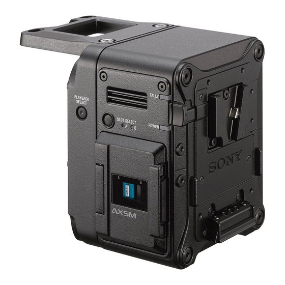
Page 13: Location Of Main Parts
Power supply DM-157 RAW codec IF-1318 Camera interface RE-340 Power control system SCN-17 Memory card interface SW-1706 Slot select switch and indicator Docking module DC-181 DC IN/OUT, camera interface IF-1308 Camera interface extension SW-1714 PB select switch and indicator AXS-R7... -
Page 14: Functions Of Onboard Switches And Led Indicators
1-3. Functions of Onboard Switches and LED Indicators 1-3-1. DC-181 Board S302 DC-181 board (Side A) Ref. No. (address) Color Description Normal state S302 (B-3) — Version update button — 1-3-2. RE-340 Board RE-340 board (Side A) AXS-R7... -
Page 15: Sw-1706 Board
Off: When a valid memory card is not inserted 1-3-4. SW-1714 Board D100 S100 SW-1714 board (Side A) Ref. No. (address) Color Description Normal state S100 (—) — PLAYBACK SELECT button — D100 (—) Green PLAYBACK SELECT indicator Lights Lights when playback of data is possible. AXS-R7... -
Page 16: Circuit Description
The RE-340 board contains the power control IC CPLD (IC107) to drive the cooling fan, POWER indicator, and TALLY lamp. This board also controls power of the SCN-17 board. DD-49 Board The DD-49 board generates three-channel +3.3 V and single-channel +5 V from the power supplied from the RE-340 board and supplies these voltages to each board. AXS-R7... - Page 17 EXIST signal to recognize installation of AXS-A memory card are sent from CN103 to the FPGA (IC0100) on the DM-157 board. The EXIST signal is also connected to the RE-340 board from CN102 to control power. Two SCN-17 boards are used in AXS-R7 because two AXS-A media slots are provided. SW-1706 Board The SW-1706 board contains the SLOT SELECT button, ACCESS lamp A, and ACCESS lamp B.
-
Page 18: Flow Of Main Signals
DC IN power is selected. The selected voltage is referred to as “SW_UNREG” hereafter. • Input overcurrent protection of DC IN A 15A fuse (F201) on the DC-181 board is installed at the DC IN input end for overcurrent protection. 1-10 AXS-R7... - Page 19 V and sends the Power Good signal to IC101. The FET (Q201) on the DD-49 board generates +3.3 V_3 from +3.3V_ 2 generated by the DC-DC converter (IC102) and sends the RE_PGOOD signal to the CPLD (IC107) on the RE-340 board. 1-11 AXS-R7...
- Page 20 The CPLD (IC107) on the RE-340 board monitors the fan rotating status and sends the PWM signal to the fan driver (IC202 and IC103) on the DD-49 board to generate a fan voltage. LED control The following LEDs are controlled by the CPLD (IC107) on the RE-340 board. • POWER indicator • TALLY lamp 1-12 AXS-R7...
-
Page 21: Notes On Replacement Of Circuit Board
1-5. Notes on Replacement of Circuit Board 1-5-1. DM-157 Board Data must be written to the new board. For details, contact your local Sony Sales Office/Service Center. 1-13 AXS-R7... -
Page 22: Updating Firmware Version
1-6. Updating Firmware Version Refer to the version update procedure. For details, contact your local Sony Sales Office/Service Center. 1-14 AXS-R7... -
Page 23: Acquiring Log Data
On completion of the acquisition, the PLAYBACK SELECT indicator starts blinking with 1 Hz. If log acquisition failes, the PLAYBACK SELECT indicator blinks with 4 Hz. Then, remove the USB memory and then retry operations from step 3. Remove the USB memory. 1-15 AXS-R7... -
Page 24: Periodic Maintenance And Inspection
When the DC fan is contaminated with dust, clean the DC fan. When cleaning the DC fan, remove it then blow the air. For the procedure to remove the DC fan, refer to “2-5. DC Fan”. DC fan 1-16 AXS-R7... -
Page 25: Circuit Protection Parts
After that, replace the defective parts. Board Name Ref. No. Address Part Name and Rating Part No. DC-181 F201 B-2/Side A Fuse (SMD) 15 A 65 VAC/DC 1-576-566-21 RE-340 F101 — Fuse (SMD) 15 A 65 VAC/DC 1-576-566-21 1-17 AXS-R7... -
Page 26: Service Tools
J-6325-400-A Torque screwdriver (3 kg•cm) (0.3 N•m) J-6252-510-A Torque screwdriver (6 kg•cm) (0.6 N•m) J-6252-520-A Torque screwdriver (12 kg•cm) (1.2 N•m) J-6252-530-A Torque screwdriver (26 kg•cm) (2.6 N•m) Commercially avail- Pliers Tightening nut of DC OUT connector able 1-18 AXS-R7... -
Page 27: Disconnecting/Connecting Fine-Wire Coaxial Cable
Connecting Insert the connector straight matching the polarity marks. Note Inserting the connector at an angle so may damage it. Insert the connector firmly as far as it will go. Polarity marks Fine-wire coaxial cable Connector 1-19 AXS-R7... -
Page 28: Lead-Free Solder
• The ordinary soldering iron can be used but the iron tip has to be applied to the solder joint for a slightly longer time. The printed pattern (copper foil) may peel away if the heated tip is applied for too long, so be careful. 1-20 AXS-R7... -
Page 29: Forming Harness Guard Ps
1-13. Forming Harness Guard PS When you use a new harness guard, fold it as shown below. Harness guard PS Valley fold Valley fold Valley fold Valley fold Valley fold 1-21 AXS-R7... -
Page 31: Replacement Of Main Parts
Tightening torque M2: 0.18 ±0.03 N·m M2.6: 0.53 ±0.07 N·m M3: 0.8 ±0.12 N·m M4: 1.4 ±0.1 N·m When using the torque driver with the notation of cN·m, interpret it as follows. Example: 0.8 N·m = 80 cN·m AXS-R7... -
Page 32: Docking Module
Docking Module Procedure Loosen the four hexagon socket bolts (anti-drop), and then remove the docking module. Docking module Hexagon socket bolt (anti-drop) M4 x 62.8 Connector (size: 3 mm) Connector Install the removed parts by reversing the steps of removal. AXS-R7... -
Page 33: Battery Harness
RE-340 board. P2 x 3 CN102 (RE-340 board) CN panel (BATT) Harness Clamper Note • When attaching the CN panel (BATT), be careful not to pinch the harness. • When connecting the harness, arrange it as shown in the figure. AXS-R7... - Page 34 Remove the battery harness. (1) Remove the four screws. (2) Pull the battery harness through the hole. P2 x 3 Battery harness Hole Install the removed parts by reversing the steps of removal. AXS-R7...
-
Page 35: Rear Case Assembly
(3) Remove the four hexagon socket bolts, and then remove the inside panel assembly. (4) Remove the button (slot select). Hexagon socket bolts M3 x 5 (size: 2 mm) P2 x 3 Memory slot cover Inside panel assembly Button (slot select) AXS-R7... - Page 36 (size: 2 mm) Outside panel assembly Remove the four hexagon socket bolts, and then remove the rear panel assembly. Hexagon socket bolts M3 x 10 (size: 2 mm) Rear panel assembly Install the removed parts by reversing the steps of removal. AXS-R7...
-
Page 37: Dc Fan
(1) Disconnect the harness from the connector (CN201) on the RE-340 board. (2) Remove the DC fan assembly. RE-340 board CN201 Harness DC fan assembly Attach two new cushions (fan) to a new DC fan. DC fan Cushion (fan) Cushion (fan) Reassemble the unit. AXS-R7... -
Page 38: Re-If-Power Harness (Disconnecting From The Connector)
(2) Remove the screw. (3) Release the harness guard PS from the boss and the slot. Harness guard PS PSW2 x 5 RE-IF-power harness Hole CN104 Slot RE-340 board Boss Install the removed parts by reversing the steps of removal. AXS-R7... -
Page 39: Re-340 Board, Dd-49 Board
Slot A Note When connecting the harnesses, observe the following instructions. • Connect the harnesses for slots A, B to the following connectors. Harness for slot A: CN302 Harness for slot B: CN303 • Tuck the harnesses under the duct. AXS-R7... - Page 40 Note • When installing the RE-340 board, tighten the screws in the following sequence: (a), (b), others. • When connecting the harness, twist it once in the direction of arrow and arrange it as shown in the figure. 2-10 AXS-R7...
- Page 41 Remove the screw, and then remove the DD-49 board from the connector (CN2500) on the DM-157 board in the direction of the arrow. DD-49 board PSW2 x 5 CN201 CN2500 (DM-157 board) Install the removed parts by reversing the steps of removal. 2-11 AXS-R7...
-
Page 42: Sw-1706 Board
• Align the boss with the hole. • Twist the harness [A] once in the direction of arrow and arrange it as shown above. • Pass the harness [B] between the two ribs. Install the removed parts by reversing the steps of removal. 2-12 AXS-R7... -
Page 43: Duct Assembly
• Before tightening four screws in step 2, arrange the two fine-wire coaxial cables under the fan section of the duct so that they are not out of the edge of the unit at portion C. • Push the two fine-wire coaxial cables into the space between the wall for fan and slot A/B. 2-13 AXS-R7... - Page 44 • Insert the two bosses of the heatsink DM into the location hole and the elongate hole of the duct, and then tighten screws. • Before tightening four screws, arrange the two fine-wire coaxial cables under the fan section of the duct so that they are inside the unit. Install the removed parts by reversing the steps of removal. 2-14 AXS-R7...
-
Page 45: Slot Assembly
Note When connecting the harnesses, observe the following instructions. • Connect the harnesses for slots A, B to the following connectors. Harness for slot A: CN302 Harness for slot B: CN303 • Tuck the harnesses under the duct. 2-15 AXS-R7... - Page 46 • When attaching the duct support plate, align the boss [A] with the hole [A]. First tighten the screw (a), and then tighten the screw (b). (Refer to the illustration.) • When attaching the slot assemblies, align the four bosses [B] with the four holes [B]. Install the removed parts by reversing the steps of removal. 2-16 AXS-R7...
- Page 47 “2-6. RE-IF-Power Harness (Disconnecting from the Connector)”) Remove the duct assembly. (Refer to “2-9. Duct Assembly”) Remove the slot assembly. (Refer to “2-10. Slot Assembly”) Procedure Remove the two radiation sheets 14X35X3 and the slot cushion. Radiation sheets 14X35X3 Slot cushion 2-17 AXS-R7...
-
Page 48: Scn-17 Board
(2) Remove the four screws, and then remove the SCN-17 board. PSW2 x 5 SCN-17 board CN102 Bosses Holes Note When attaching the SCN-17 board, align the two bosses with two holes. Install the removed parts by reversing the steps of removal. 2-18 AXS-R7... -
Page 49: Dm-157 Board
When installing the heat sink DM, observe the following instructions. • Confirm that the fine-wire coaxial cable is arranged as shown above. • Align the two bosses with the location hole and the elongate hole. • Tighten the screws into the holes pointed by arrows. 2-19 AXS-R7... - Page 50 When installing the DM-157 board, observe the following instructions. • Align the boss of the front panel with the location hole. • First tighten the screw (a) shown in the illustration, and then tighten the other three screws. 2-20 AXS-R7...
- Page 51 Fine-wire coaxial cable Arrangement of harnesses Harness Harness Fine-wire coaxial cable Note When connecting the harnesses and the fine-wire coaxial cable, arrange them as shown in the figure. Install the removed parts by reversing the steps of removal. 2-21 AXS-R7...
-
Page 52: If-1318 Board
Remove the DM-157 board. (Refer to “2-12. DM-157 Board”) Procedure Remove the DM protective sheet. DM protective sheet Arrangement of harness Harness DM protective sheet Note When attaching the DM protective sheet, arrange the harness as shown in the figure. 2-22 AXS-R7... - Page 53 (1) Disconnect the two harnesses from the two connectors (CN102, CN103) on the IF-1318 board. (2) Disconnect the fine-wire coaxial cable from the connector (CN101) on the IF-1318 board. CN101 CN103 Harness Contact (gold) Fine-wire Harness CN102 coaxial cable IF-1318 board 2-23 AXS-R7...
- Page 54 • Provide a margin for the harness between the IF-1318 board and the tape AS (0932). Note The connector CN100 on the IF-1318 board has a floating mechanism. After attaching the plate (IF), confirm that the floating mechanism works correctly. 2-24 AXS-R7...
- Page 55 Four lead wires Three lead wires Three lead wires IF-1318 board Tape AS (0932) Note When connecting the harness, locate each connector by the placement of leads as shown above. Install the removed parts by reversing the steps of removal. 2-25 AXS-R7...
-
Page 56: If-1308 Board
Remove the docking module. (Refer to “2-2. Docking Module”) Procedure Remove the six screws. P2.6 x 5 (Tightening torque: 0.33±0.02 N·m) Turn the release lever to the position shown below, and then remove the front cover G. Front cover G Release lever 2-26 AXS-R7... - Page 57 When attaching the docking reinforcement (OUT) and the docking reinforcement (IN), align the three bosses with the three holes respectively. Turn the release lever to the position shown below, and then remove the front cover assembly. Front cover assembly Release lever 2-27 AXS-R7...
- Page 58 Slide sheet Slide sheet Holes Bosses Bosses Note When attaching the two slide sheets, align the two bosses with the two holes respectively. Remove the two screws, and then remove the CN guard. PSW2 x 5 CN guard 2-28 AXS-R7...
- Page 59 When connecting the fine-wire coaxial cable, observe the following instructions. • Hook the fine-wire coaxial cable to the rib of the harness holder G. • Pass the harness on the right side of the connector (CN202) on the DC-181 board. 2-29 AXS-R7...
- Page 60 Tilt the harness holder G as shown below and remove it from the IF-1308 board assembly. Harness holder G IF-1308 board assembly Disconnect the two harnesses from the two connectors (CN101, CN103) on the IF-1308 board. IF-1308 board assembly CN103 Harness CN101 Harness 2-30 AXS-R7...
- Page 61 PSW2 x 5 CN cover Insulating sheet IF-1308 board Holes Sub plate G Bosses Note When attaching the sub plate G, align the two bosses with the two holes. 11. Install the removed parts by reversing the steps of removal. 2-31 AXS-R7...
-
Page 62: Dc-181 Board
(2) Disconnect the four harnesses from the four connectors (CN202, CN204, CN205, CN303) on the DC-181 board. Harness PSW2 x 5 CN202 Harnesses CN204 DC-181 board assembly Harness CN205 CN303 Note When attaching the DC-181 board assembly, be careful not to pinch the harnesses. 2-32 AXS-R7... - Page 63 (2) Disconnect the two harnesses from the two connectors (CN102, CN203) on the DC-181 board. (3) Disconnect the fine-wire coaxial cable from the connector (CN101) on the DC-181 board. Fine-wire coaxial cable Harness Contact (gold) CN203 Harness DC-181 board CN102 Hole CN101 Install the removed parts by reversing the steps of removal. 2-33 AXS-R7...
-
Page 64: Dc Out Connector
• When attaching the DC OUT connector, apply locking compound to one screw portion of the DC OUT connector. • Do not use the star washer supplied with the new DC OUT connector. Install the removed parts by reversing the steps of removal. 2-34 AXS-R7... -
Page 65: Dc In Connector
Remove the docking module. (Refer to “2-2. Docking Module”) Remove the IF-1308 board assembly. (Refer to “2-14. IF-1308 Board”) Remove the DC-181 board assembly. (Refer to “2-15. DC-181 Board”) Procedure Remove the tape AS (0932). Harness Tape AS (0932) 2-35 AXS-R7... - Page 66 Remove the two screws, and then remove the DC IN connector. P2.6 x 5 DC IN connector Install the removed parts by reversing the steps of removal. 2-36 AXS-R7...
-
Page 67: Sw-1714 Board
(1) Disconnect the harness from the connector (CN100) on the SW-1714 board. (2) Remove the screw, and then remove the SW-1714 board. SW-1714 board Switch board holder (G) P2 x 3 CN100 Harness Install the removed parts by reversing the steps of removal. 2-37 AXS-R7... -
Page 68: Sw Cover (Assign)
Remove the guide light (G). (1) Draw the guide light (G) in the direction of the arrow A. (2) Rotate the guide light (G) in the direction of the arrow B. (3) Remove the guide light (G). Guide light (G) 2-38 AXS-R7... - Page 69 After attaching the PB select sheet, confirm that the round projection of the SW cover (assign) comes out of the hole of sheet. Remove the SW cover (assign). SW cover (assign) Install the removed parts by reversing the steps of removal. 2-39 AXS-R7...
-
Page 71: Spare Parts
Therefore, specified parts should be used in the case 指定の部品を使ってください。 of replacement. 2. Standardization of Parts 2. 部品の共通化 Some repair parts supplied by Sony differ from those ソニーから供給する補修用部品は,セットに使われ used for the unit. These are because of parts common- ているものと異なることがあります。 ality and improvement. -
Page 72: Exploded Views
4-593-338-01 s CLAW, LOCK 4-593-339-01 s PLATE, CLAW FIXED 4-593-341-01 s BUTTON (SLOT SELECT) 4-598-993-01 s RETAINER, MEDIA 4-598-994-01 s SPRING, MEDIA RETAINER 4-599-119-01 s SHAFT, HINGE 4-599-120-01 s FRICTION, HINGE 4-599-121-01 s SPRING, COMPRESSION 4-599-979-01 s CAP SCREW(HEXAGON, LOW HEAD)M3 AXS-R7... -
Page 73: Rear Case Block
3-624-455-01 s TUBE,SHIELD 3-826-988-02 s LOCK,SLIDE 7-627-553-28 s SCREW,PRECISION +P 2X2.5 3-855-938-01 s SCREW [+PSW M2X5] 4-592-826-01 s MESH RETAINER (OUTSIDE) 4-592-827-01 s MESH RETAINER (BOTTOM) 4-592-831-01 s SCREW, RR ORNAMENT 4-592-833-01 s CN PANEL (BATT) 4-593-024-01 s CUSHION (OUT), WATERPROOF AXS-R7... -
Page 74: Main Duct Block
A-2143-630-A s DD-49 COMPLETE 1-855-374-11 s DC FAN 1-969-452-11 s HARNESS, SUB (HP-KY) 3-257-200-01 s CLAMP, CORD 3-855-938-01 s SCREW [+PSW M2X5] 4-592-829-01 s HARNESS GUARD PS 4-592-832-01 s PLATE, DUCT SUPPORT 4-593-907-01 s CUSHION (DUCT), WATERPROOF 4-594-022-01 s CUSHION (FAN) AXS-R7... -
Page 75: Slot Assembly
Slot Assembly Part No. SP Description A-2143-628-A s SCN-17 COMPLETE 1-971-479-11 s SUB HARNESS (SCN-POWER) 3-855-938-01 s SCREW [+PSW M2X5] 4-480-706-01 s RADIATION SHEET 14X35X3 4-598-199-01 s SPRING, SLOT RETAINER 4-598-200-01 s CUSHION, SLOT 4-598-201-01 s SHEET, SLOT SLIDER AXS-R7... -
Page 76: Front Panel Block
1-971-483-11 s SUB HARNESS (DM-IF2) 1-971-484-11 s SUB HARNESS (DM-SW-LED) 3-624-455-01 s TUBE,SHIELD 3-855-938-01 s SCREW [+PSW M2X5] 4-119-362-01 s SHEET (2828), LENS RADIATION 4-408-576-01 s TAPE (AS (0932)) 4-437-492-01 s SHEET (VCA2), RADIATION 4-458-196-01 s SHEET, HEAT TRANSFER (A) AXS-R7... -
Page 77: Docking Module
1-971-480-11 s SUB HARNESS (EXTIF-POWER) 3-694-181-03 s TYPE1, AROCK PRECISION +P2.6X5 3-080-203-21 s SCREW(M2),LOCK ACE,P2 3-624-455-01 s TUBE,SHIELD 3-855-938-01 s SCREW [+PSW M2X5] 4-408-576-01 s TAPE (AS (0932)) 4-458-407-01 s GUARD, CN 4-458-413-01 s SPRING,COMPRESSION 4-458-417-02 s COVER, CN AXS-R7... -
Page 78: Supplied Accessories
3-3. Supplied Accessories Q'ty Part No. SP Description 4pcs 4-562-604-01 s BOLT(1/4-20 UNC),HOLE HEXAGON 4-598-229-01 s COVER, TOP 4-685-095-01 s MANUAL, INSTRUCTION [Supplied for SY] 4-685-095-11 s MANUAL, INSTRUCTION [Supplied for CN] AXS-R7... -
Page 79: Diagrams
BATT-SCL FAN_PWM_RE Q203,204 IC103 IC201 BATT-SDA FAN_PWM_RE BATT-ID D204:TALLY DEMODULATOR DETECT SRPACK_EXIST D206:POWER ON Q202,203 +3.3V_4 5 to +3.3V_4 +5.0V +5.0V DRIVE FAN_OUT 41,42 X101 1.8432MHz CN202 SLOT_SEL_SW CN302 SRPACK_EXIST0 +3.3V_DC 1,2,3,4 CN303 SRPACK_EXIST1 +3.3V_DC 1,2,3,4 CN201 FAN_SENCE FAN_OUT AXS-R7... -
Page 80: Frame Wiring
CN0400 CN2500 200P SUB HARNESS (HP-KY) JTAG 200P CN201 D100 CN100 CN303 SUB HARNESS (KY-PSW) SW-1714 DD-49 SELECT S100 CN202 200P 200P CN302 CN301 CN202 CN104 RE-340 CN303 SUB HARNESS (RE-IF-POWER) CN103 CN201 CN102 JTAG SUB HARNESS (ADPT-BATT) BATTERY AXS-R7... -
Page 81: Revision History
Revision History Date History Contents 2016. 9 1st Edition ― 9-976-994-01 AXS-R7... - Page 84 AXS-R7 (SY) Printed in Japan Sony Corporation AXS-R7 (CN) J, E 2016. 9 08 9-976-994-01 © 2016...