Table of Contents
Advertisement
Quick Links
Advertisement
Table of Contents

Related Manuals for Honeywell COMBISAFE SkyReach 8100


Summary of Contents for Honeywell COMBISAFE SkyReach 8100
- Page 1 8100 SkyReach Anchor USER INSTRUCTIONS 0158 - EN 795:2012-B...
-
Page 2: Table Of Contents
CONTENTS General Quick Guide Safety instructions Technical data SkyReach Anchor Personal Fall Protection Equipment Attachments Optional items Attachment installation Cast-In Sleeve installation Steel Flange Clamp installation Assembly Installation by hand Installation by crane Dismantling Working procedure Changing the anchor point Maintenance Safety check before initial use Cleaning... -
Page 3: General
SkyReach Anchor Safety instructions General The SkyReach Anchor is a product that has been designed to prevent falls from heights, mainly during all work associated with decking for horizontal formwork operations. Together with specific attachments and certified Personal Fall Protection Equipment (PFPE) it will create a personal fall protection system which contributes to a safe workplace. -
Page 4: Quick Guide
Safety instructions SkyReach Anchor Quick Guide # 8100 # 8200 EN 795:2012 Type B... -
Page 5: Safety Instructions
SkyReach Anchor Safety instructions Safety instructions The SkyReach Anchor is intended for the purpose stated in this user instruction only, any other use is not allowed. The SkyReach Anchor is a personal fall protection anchor device, used to protect workers operating at height. If used incorrectly there is a potential risk of accidents to both the user and other people in the vicinity. - Page 6 Safety instructions SkyReach Anchor • When using a retractable fall arrest block, the certification of this product is only valid when the prescribed block is used, hence it is tested and approved in combination with the SkyReach Anchor. • PFPE that is used together with the SkyReach Anchor must be CE-certified and approved in the specific country of use.
- Page 7 SkyReach Anchor Safety instructions Fall clearance Note that it is necessary that enough free distance is verified to closest underlying object, see Figure 2 below. Figure 2. Explanation of fall clearance A: 0,7 [m] Vertical deflection of the SkyReach Anchor Point B: X Braking distance of the PFPE.
- Page 8 Safety instructions SkyReach Anchor Periodic inspection/inspection after a fall To ensure the function and safety of the components, a safety inspection of the SkyReach Anchor, the attachments and the PFPE, needs to be done by a competent person at least once every 12 months.
-
Page 9: Technical Data
SkyReach Anchor Technical data Technical data SkyReach Anchor The SkyReach Anchor is designed to be a lightweight product and is easily foldable for moving and configured to be space-saving when transporting or storing the item, see Figure 3. To secure both positions (assembled mode and folded mode) the attached Lock Pin is used. - Page 10 Technical data SkyReach Anchor SkyReach Anchor Labels and Markings Figure 4 below shows all the labels and markings of the SkyReach Anchor. The following figures (Figure 5, Figure 6 and Figure 7) are showing these important elements. Figure 4. Labels and markings on the SkyReach Anchor 1.
- Page 11 SkyReach Anchor Technical data Figure 5. A close-up of the ID Plate which includes the serial number. #8200 Type B 0158 EN 795:2012 SKYREACH Anchor #8100 Combisafe International AB Tallbacksgatan 16A,19572 Rosersberg, TP TC Sweden 019/2011 #8500/8501 #8800 © Combisafe International AB 100583 -1947 Type B #8100 Type E...
-
Page 12: Personal Fall Protection Equipment
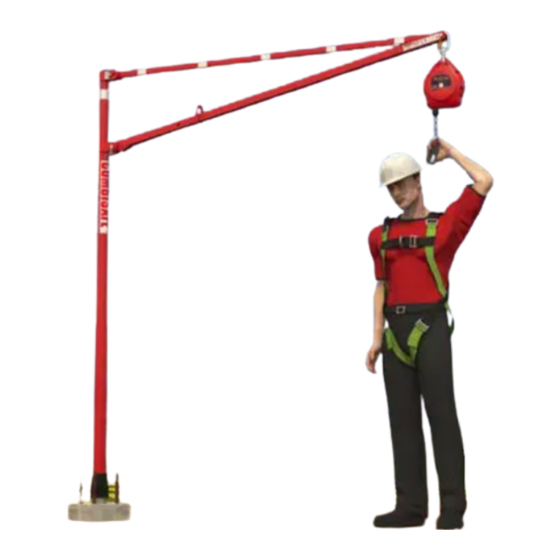
Technical data SkyReach Anchor Personal Fall Protection Equipment To create a complete system to protect the operative when working at height, the SkyReach Anchor needs to be equipped with Personal Fall Protection Equipment (PFPE). Figure 8 shows an example on how to equip the SkyReach Anchor with recommended PFPE. - Page 13 SkyReach Anchor Technical data Figure 8. The figure shows a fully PFPE equipped SkyReach Anchor Item Art no. Designation Weight 8100 SkyReach Anchor 25 kg Full body harness certified to EN 361 CM1002889 Miller extra webbing, 0.3 m 0,2 kg CM1011729 Falcon Fall Arrest Block, 6.2 m 4 kg...
-
Page 14: Attachments
Technical data SkyReach Anchor Attachments The SkyReach Anchor has been tested and approved to be used together with the following described attachments. Please remember that the SkyReach Anchor CE-certification is valid only when used with these attachments. Cast-in Sleeve (Art. 8200) The Cast-in Sleeve is a metal socket that shall be cast directly into the concrete on-site to house the SkyReach Anchor, see Figure 9. - Page 15 Technical data SkyReach Anchor Steel Flange Clamp Kit MkII - NEW (Art. 8501) This Steel Flange Clamp MkII - 8501 is new substitute for old clamp 8500. Clamp is designed to be placed onto pillars with flange width between 12 and 45 cm, see Figure 11. For the use of each SkyReach Anchor, two pieces of the Steel Flange Clamp MkII and one piece of the Steel Flange Clamp Cup is needed.
- Page 16 SkyReach Anchor Technical data Loading System MkII (Art. 8800) The SkyReach Anchor can be used together with the COMBISAFE Loading System MkII for the safe loading and unloading of e.g. flatbed lorries, see Figure 12. This combination is certified according to EN 795:2012 Type E. Please see UI Loading System MkII, provided by Combisafe.
-
Page 17: Optional Items
Technical data SkyReach Anchor Optional items The following items are not delivered as standard together with the SkyReach Anchor but can be ordered separately if required. Levelling Element (Art. 83416) The levelling element is a steel tube with a level on the top, see Figure 13. - Page 18 SkyReach Anchor Technical data Latex Cone (Art. 100608) The Latex Cone is a weather protective gasket which is placed onto the mast of the SkyReach Anchor, see Figure 15. The purpose is to prevent water and dirt getting into the Cast-In Sleeve when the SkyReach Anchor is in place in the sleeve, and therefore preventing the SkyReach Anchor from becoming frozen in the sleeve.
-
Page 19: Attachment Installation
Attachment installation SkyReach Anchor Attachment installation Cast-In Sleeve installation 1. After pouring concrete into the column mold, place a Cast-In Sleeve in the upper side of the column while the concrete is still wet. The Sleeve has to be protruding 30-80 mm above the top surface of the column. - Page 20 SkyReach Anchor Attachment installation Figure 17. Levelling the Cast-in Sleeve body. NOTE During concrete hardening, uplift of the Cast-in Sleeve may occur. To prevent this, the tube should be encumbered or alternatively may be wired to rebars to keep the protruding tolerance.
- Page 21 Attachment installation SkyReach Anchor As an example; if the maximum aggregate size is 16 mm, a Ø20 mm vertical bar and a Ø12 mm horizontal bar are used in a column. The minimum size to closest bar must then be 21 mm, hence the determined value is d = 16+5=21 mm.
- Page 22 SkyReach Anchor Attachment installation Load on structure The structure upon which the the SkyReach Anchor is mounted, must be capable of carrying the imposed loads. The maximum forces transmitted to the structure during service are shown in Figure 19. Figure 19. Maximum loads transmitted to the structure...
-
Page 23: Steel Flange Clamp Installation
Attachment installation SkyReach Anchor Steel Flange Clamp installation The Steel Flange Clamp installation is shown in Figure 20. 1. Loosen the adjustment nut and increase the gap of the jaws enough to place the clamp over the beam flange. 2. Make sure the centre-to-centre distance between the upper clamp and the lower clamp is 700 mm, and that the clamps are perpendicular to the column. - Page 24 SkyReach Anchor Attachment installation 5. Install the cup into the lower Steel Column Clamp. There is a pin located on the side of the cup, which has to pass into the grooves on each lug on the clamp. The grooves in the lugs are not aligned so the cup must be turned to pass through both lugs.
- Page 25 Attachment installation SkyReach Anchor Steel Flange Clamp Kit MkII Instalation The Steel Flange Clamp Kit MkII installation is shown in Figure 22. 1. Loosen the adjustment nut and increase the gap of the jaws enough to place the clamp over the beam flange. 2.
- Page 26 SkyReach Anchor Attachment installation 5. Install the cup into the lower Steel Flange Clamp MkII on the column. Once Cup is inserted into lower Steel Flange Clamp MkII, Insert Quick Release Pin into Cup locking hole and secure it. See Figure 23 for a detailed view. Figure 23.
- Page 27 Attachment installation SkyReach Anchor Load on structure The structure upon which the SkyReach Fall Arrest System is mounted must be capable of carrying the imposed loads. The maximum forces transmitted to the structure are shown in Figure 24. Figure 24. Maximum loads transmitted to the structure. NOTE It is important to take into consideration the column quality and stability under load.
-
Page 28: Assembly
SkyReach Anchor Assembly Assembly In this document two different methods to assemble and install the SkyReach Anchor will be described. Either just by hand, or with the help of a crane. The outcome of your risk analysis, depending on the site, will decide what method to use. Installation by hand Due to the lightweight design of the SkyReach Anchor it can easily be moved and installed by one person only. - Page 29 Assembly SkyReach Anchor NOTE Make sure that the SkyReach Anchor is inserted the correct length by observing the Insertion Marking Label. The upper edge of the sleeve must be aligned with the lower edge of the label, see Figure 26 for a closer illustration of the label. Figure 26.
- Page 30 SkyReach Anchor Assembly 3. Proceed either by; (1) fully assemble the SkyReach Anchor by placing the brace hook into lower lugs at the mast according to Figure 28, secure the brace with the Lock Pin according to the figure. Then connect the fall arrest block to the anchor point and make sure it is correctly secured.
-
Page 31: Installation By Crane
Assembly SkyReach Anchor Figure 29. Attaching a 6,2m Falcon Fall Arrest Block at a lower height. 4. Make sure that the steps in the safety check in the Maintenance chapter are followed and executed. Now the SkyReach Anchor is ready to use! NOTE Make sure that the Lock Pin is properly installed, latch is dropped and that it is secured with the wire. - Page 32 SkyReach Anchor Assembly 1. Mount the SkyReach Anchor in four easy steps, please see Figure 30. 1. Place the folded SkyReach Anchor on the ground and unpin the Lock Pin to release the SkyReach Anchor brace and boom. 2. Arrange the position of the boom. 3.
- Page 33 Assembly SkyReach Anchor 2. The next step is to connect the fall arrest block. Make sure that the component is correctly attached and secured to the SkyReach Anchor. Figure 31 shows how the 6,2 m Falcon Fall Arrest Block is attached to the anchor point. Figure 31.
- Page 34 SkyReach Anchor Assembly NOTE Check that the Cast-In Sleeve is empty and free of dirt (e.g. building debris, concrete, ice) prior installation of the SkyReach Anchor. Make sure that the SkyReach Anchor is inserted the correct length by observing the Insertion Marking Label. The upper edge of the sleeve must be aligned with the lower edge of the label, see Figure 33.
-
Page 35: Dismantling
Assembly SkyReach Anchor 4. Make sure that all steps in the safety check in the Maintenance chapter are followed and executed. Now the SkyReach Anchor is ready to use! Dismantling The installation procedure should be performed in the reverse order when dismantling. When lifting SkyReach from its position by crane, check that there is no part bent or damaged. -
Page 36: Working Procedure
SkyReach Anchor Working procedure Working procedure To ensure proper function of the SkyReach Anchor, the proposed method of installation has to be used in a controlled and disciplined manner. Failure to follow this working method could result in a fall which could result in injury or even death. Always perform a risk analysis and take actions before proceeding. - Page 37 Working procedure SkyReach Anchor If using edge protection, the above statement do not have to be considered, and the SkyReach can be inserted as close to the edge as needed. The pictures in the following installation description shows the method when edge protection is used. Any operative performing this action should be wearing: •...
- Page 38 SkyReach Anchor Working procedure Figure 35. Decking process. 3. After all accessible areas provided by the SkyReach Anchor in use are covered, the connection has to be changed and the sequence started again. The areas protected by the SkyReach Anchors from adjacent columns will overlap, permitting workers to support each other, and ensure a common, progressive leading edge.
- Page 39 Working procedure SkyReach Anchor Figure 36. Decking process after changing anchor point. NOTE The leading edge of all decking sections has to be continuously spread across the whole width of the circular work area. No decking section should stick out too much in front of the decking section beside it.
- Page 40 SkyReach Anchor Working procedure One example of wrong way of formwork installation is shown in Figure 37. Figure 37. Wrong way of formwork installation, this is not allowed...
- Page 41 Working procedure SkyReach Anchor Changing anchor The SkyReach Anchor has been designed to allow the operator to change anchor before unhooking themselves from the first anchor, and thus provide safety at all times, see Figure 38. The use of the recommended 0.3 m Extra Webbing attached to the Full body harness allows quick and comfortable attaching of a snap hook or fast disengagement if any dangerous situation occurs.
-
Page 42: Maintenance
SkyReach Anchor Maintenance Maintenance Safety check before each use Checking of the system shall be performed before each use, if any of the listed statements below are not met, make sure to correct any issue before using the product. Checking includes the following steps: SkyReach Anchor: •... - Page 43 Maintenance SkyReach Anchor Cast-In sleeve: • Ensure that no drill holes have been made. • Ensure that no corrosion that can affect the strength of the compo- nent has occurred. • Ensure that there is no weld damage or deformation to any part of the component.
-
Page 44: Cleaning
SkyReach Anchor Maintenance Cleaning Periodically clean the exterior of the parts. Wipe all parts to remove grease or dirt using a damp cloth and if needed use mild detergent, towel dry. Do not use any detergent that could affect the strength of the parts. - Page 46 EN/ Notified body having carried out the EU test of type: /BG/ : /CS/ Oznámený orgán, který provedl EU test typu: /DA/Godkendt organisme, der har udført EU-ty- peafprøvningen: /DE/ Zugelassene Stelle, welche die EU-Typprüfung durchge führt hat: /EL/: : /ES/ Organismo notificado que ha realizado el examen UE de tipo: /ET/Teavi- tatud asutus, mis tegi EL-tüübikatse: FI/ llmoitettu jãrjestõ, joka on suorittanut EU-tyyppitarkastuksen: /FR/ Organisme notifié...
- Page 47 2016/425 e todos os outros requisitos de diretivas da União Europeia. O texto completo da Declaração de Conformidade encontrase em: /RO/ Honeywell Fall Protection declară prin prezentul că acest produs respectă cerin ele esen iale și alte prevederi relevante ale em: /RO/ Honeywell Fall Protection declară...
-
Page 48: Combisafe International Ab
COMBISAFE International Ltd Safety Centre, Cheaney Drive, Grange Park Northampton UK-NN4 5FB Tel.: +44 (0)160 4 660600, Fax: +44 (0)160 4 662960 info@combisafe.com, www.combisafe.com...