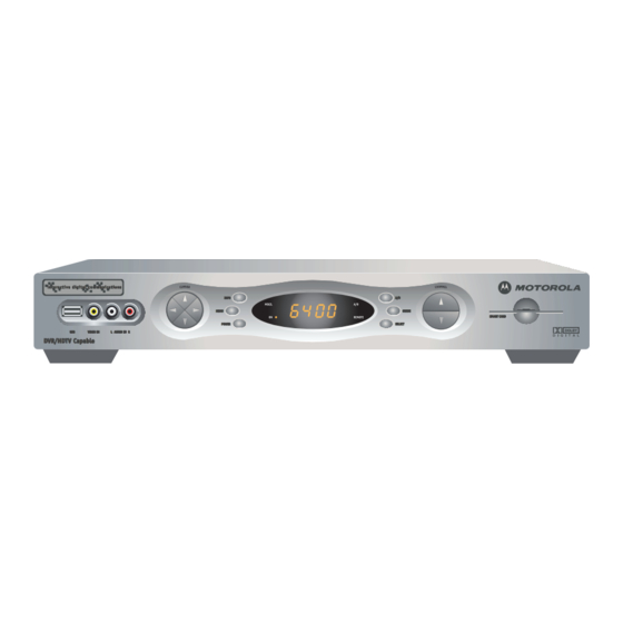
Motorola dct6412 User Manual
High definition dual tuner dvr cable receiver
Hide thumbs
Also See for dct6412:
- User's reference manual (71 pages) ,
- User manual (41 pages) ,
- Reference manual (10 pages)
Table of Contents
Advertisement
Quick Links
Advertisement
Table of Contents

Related Manuals for Motorola dct6412


Summary of Contents for Motorola dct6412
- Page 2 REPAIRS If you find the unit in need of repair, call Motorola Support at 1-866-668-2271 or 1-866-MOT-BCS1. NOTE TO CATV SYSTEM INSTALLER This reminder is provided to call the CATV system installer’s attention to Article 820-40 of the NEC that...
- Page 3 Read instructions All the safety and operating instructions should be read before the appliance is operated. Retain instructions The safety and operating instructions should be retained for future reference. Heed warnings All warnings on the appliance and in the operating instructions should be adhered to. Follow instructions All operating and use instructions should be followed.
- Page 4 Outdoor Antenna Grounding If an outside antenna or cable system is connected to the equipment, be sure the antenna or cable system is grounded as to provide some protection against voltage surges and built-up static charges. Lightning For added protection for this equipment during a lightning storm, or when it is left unattended and unused for long periods of time, unplug it from the wall outlet and disconnect the antenna or cable system.
-
Page 5: Regulatory Information
Motorola will not be liable to anyone for the end user's failure to use and/or dispose of batteries in the proper manner and in accordance with such laws, rules and regulations, or for any defect contained in batteries which may cause injury damage to persons or property. -
Page 6: Software License
TERMINATE AUTOMATICALLY if you fail to comply with the terms of this License. Motorola is not responsible for any third party software that is provided as a bundled application, or otherwise, with the Software or that is downloaded to, or otherwise installed on, the Product. - Page 7 (such as translation, transformation or adaptation) without written permission from Motorola, Inc. Motorola reserves the right to revise this publication and to make changes in content from time to time without obligation on the part of Motorola to provide notification of such revision or change. Motorola provides this guide without warranty of any kind, either implied or expressed, including but not limited to, the implied warranties of merchantability and fitness for a particular purpose.
-
Page 8: Table Of Contents
Connecting Your DCT* to a HDTV – Video Only ... 18 Connecting Your DCT* to a HDTV – Audio Only... 20 Connecting Your DCT* to an A/V Receiver – Audio Only ... 22 Connecting Your DCT* to a Stereo TV ... 24 Connecting Your DCT* to a Stereo TV and Stereo VCR... - Page 9 Recording Your Connections ... 30 Data Devices ... 31 Data Features ... 31 Troubleshooting ... 32...
-
Page 10: Introduction
High Definition Dual Tuner DVR Cable Receiver, one of the most advanced interactive digital cable receivers available today. With the DCT*, Motorola has merged the extraordinary features of digital cable – the seemingly endless programming options, interactive program guides, Video on Demand (VOD), and commercial free, CD quality music – with the flexibility of a dual tuner digital video recorder (DVR) and the incredible picture quality and sound of high definition TV (HDTV). -
Page 11: Power Switch
Connects to a CD player or stereo tuner ETHERNET* Supports PC networking ETHERNET CABLE USB* Connects to support devices AUDIO OUT (R/L) Connects to audio input of a stereo receiver INFO MSGS. POW ER POWER indicator Lights to indicate DCT* is on AUDIO IN (R/L)*... -
Page 12: Select Switch
RECORD Indicator Lights to indicate the DVR is recording SELECT switch Selects menu options GUIDE switch Displays the program guide OPTION switch Reserved for future use OPTION RECORD GUIDE REMOTE SELEC T REMOTE indicator Lights to indicate remote control is in use Display Displays channel number and time of day... -
Page 13: Operation
For best audio quality, use the remote control to set the DCT* to approximately ¾ of the maximum volume level and then adjust the audio levels on external devices such as your TV or A/V Receiver. Interactive Program Guide The interactive program guide displays information about TV programs and enables you to access features such as Parental Control or Pay-Per-View. -
Page 14: Digital Video Recorder (Dvr)
DCT6400 Series User Guide DIGITAL VIDEO RECORDER (DVR) The DCT* is equipped with an internal hard drive for DVR functionality, which provides the ability to record both standard definition TV (SDTV) and high definition TV (HDTV) programs. Storage time depends on the video format and the bit rate at which it is received. - Page 15 Simultaneously Record Two Shows Record two programs from two different channels at the same time. Simultaneously Record Two Shows and Watch a Recorded Program Watch a program recorded on your DCT* while recording up to two other programs at the same time. You can also easily switch viewing the pre-recorded program and either of the programs you’re recording.
-
Page 16: Optimizing Your Dct* For High Definition Tv
TV. The Motorola DCT* delivers high-quality video for HDTVs using the YPbPr (component), DVI-D, and IEEE 1394 connectors. This section describes how to use the on-screen display to set your DCT* to automatically optimize both standard and HD video based on your HDTV and personal preferences. - Page 17 Press the MENU on-screen display menu appears listing the settings you can configure. Use your remote control or the cursor keys on the front panel to navigate the on-screen display: Press the ▲ and ▼ keys to highlight the setting you wish to change.
-
Page 18: User Settings
User Settings Setting Description TV Type Sets the aspect ratio. The front panel display indicates the type you select. Defaults to 16:9. Options are 16:9 for wide screen TVs or 4:3 LETTERBOX or 4:3 PAN/SCAN for standard TVs: DVI/YPbPr Sets the video display format for the component video Output outputs. - Page 19 Setting Description 4:3 Override Sets the display format for 4:3 standard-definition programming. If the YPrPb Output is set to 1080i, 720p, or 480p, this setting defaults to 480i. If the YPrPb Output is set to 480i, this setting defaults to OFF and cannot be changed. Options are: Closed Caption Turns closed captions off or on.
- Page 20 Setting Description Background Sets the background color for closed captions. Defaults to Color AUTO. Options are AUTO, WHITE, BLACK, RED, GREEN, BLUE, YELLOW, MAGENTA, or CYAN. Background Sets the background opacity for closed captions. Defaults to Opacity AUTO. Options are AUTO, TRANSPARENT, TRANSLUCENT, SOLID, or FLASHING.
-
Page 21: On-Screen Graphics
ON-SCREEN GRAPHICS The DCT* can generate graphics that overlay the video programming or fill the entire television screen. Common examples include on-screen menus (such as the User Setting menu), closed captions, and interactive program guides. The DCT* overlays these graphics whenever you open a menu, enable closed captions, or scroll through a program grid. -
Page 22: Connecting Your Dct
Stereo TV and Stereo VCR A/V Receiver, TV, and VCR In this manual, DCT* refers to the DCT6400 Series of High Definition Cable Receivers: DCT6412 and DCT6416. Before you move or change components on your entertainment system, review the following: For basic cable connections, use 75-ohm coaxial cables equipped with F-type connectors. -
Page 23: Video Connection Options
Video Connection Options The DCT* offers five different video connection options. Component video, DVI, and IEEE 1394 allow you to view both HD and standard TV programming. Composite video and RF coaxial connections allow you to view only standard definition TV programming. To determine whether your TV features component video, DVI, IEEE 1394, S-Video, or composite video, check the manual supplied with your TV. -
Page 24: Important Safety Considerations
Important Safety Considerations inch US B VIDE O IN L AU DIO IN R Dual Tuner DVR / HDTV Capable Follow these important safety guidelines when positioning and connecting the DCT*: Position the DCT* with at least 2 inches of space above and on all sides Do not block the slots and openings in the DCT* Do not place anything on top of the DCT*... -
Page 25: Connecting Your Dct* To A Hdtv - Video Only
CONNECTING YOUR DCT* TO A HDTV – VIDEO ONLY Component video connection connection CABLE Cable in DVI-HDTV CABLE/ ANTENNA IN IEEE 1394 IEEE 1394 connection VIDEO ETHERNET SPDIF AUDIO IN DVI-D OUT AUDIO OUT Pass Card Either / or HDTV Component Video Input DCT6400 Series... - Page 26 DCT* and the HDTV. To connect the audio connections for your HDTV, proceed to the following page. To connect your audio connections for an A/V receiver, go to “Connecting Your DCT* to an A/V Receiver – Audio Only.”...
-
Page 27: Connecting Your Dct* To A Hdtv - Audio Only
CONNECTING YOUR DCT* TO A HDTV – AUDIO ONLY Audio Optical Digital audio connection connection connection DCT6400 Series VIDEO ETHERNET SPDIF AUDIO IN IEEE 1394 DVI-D OUT S-VIDEO CABLE AUDIO OUT OPTICAL Pass Card SPDIF Optional Optional HDTV INPUT DIGITAL INPUT COAX AUDIO LEFT CABLE/... - Page 28 Connecting HDTV – Audio Only Connect the stereo audio cable to the the DCT* and the HDTV. If your equipment supports it: The optical ( OPTICAL SPDIF may be used in place of the stereo audio outputs ( most cases these outputs offer a higher level of audio quality, including support for 5.1 Surround Sound.
-
Page 29: Connecting Your Dct* To An A/V Receiver - Audio Only
CONNECTING YOUR DCT* TO AN A/V RECEIVER – AUDIO ONLY Audio Digital audio connection connection CABLE AUDIO VIDEO VIDEO S-VIDEO CABLE/TV VIDEO 2 Optical connection VIDEO ETHERNET SPDIF AUDIO IN DVI-D OUT AUDIO OUT Pass Card Either / or DIGITAL INPUT... - Page 30 Connecting an A/V Receiver – Audio Only There are three options available for audio connections to your A/V receiver: Optical ( OPTICAL SPDIF Coaxial ( SPDIF Stereo audio ( AUDIO R If your equipment supports it, the optical ( ) audio outputs may be used in place of the stereo audio outputs SPDIF and L).
-
Page 31: Connecting Your Dct* To A Stereo Tv
CONNECTING YOUR DCT* TO A STEREO TV RF (75 ohm) connection CABLE Cable in CABLE/ ANTENNA IN S-Video Video connection connection VIDEO ETHERNET SPDIF AUDIO IN DVI-D OUT AUDIO OUT Pass Card Stereo TV INPUT S-VIDEO VIDEO AUDIO LEFT AUDIO RIGHT Audio connection DCT6400 Series... -
Page 32: Connecting A Stereo Tv
Connecting a Stereo TV Connect an RF coaxial cable to the cable wall outlet and the connector on the DCT*. CABLE IN Connect the stereo audio cable to the the DCT* and the stereo TV. Connect a video cable to the INPUT VIDEO connectors on the DCT* and the TV. -
Page 33: Connecting Your Dct* To A Stereo Tv And Stereo Vcr
CONNECTING YOUR DCT* TO A STEREO TV AND STEREO VCR RF (75 ohm) Video connection connection ETHERNET CABLE Cable in Stereo VCR INPUT CABLE/ AUDIO VIDEO AUDIO ANTENNA IN To TV Audio connection VIDEO SPDIF AUDIO IN DVI-D OUT S-VIDEO AUDIO OUT Pass Card OUTPUT... -
Page 34: Connecting A Stereo Tv And Stereo Vcr
Connecting a Stereo TV and Stereo VCR Connect an RF coaxial cable to the cable wall outlet and the connector on the DCT*. CABLE IN Connect a stereo audio cable to the on the DCT* and the VCR. Connect a video cable to the INPUT VIDEO Connect a stereo audio cable to the connectors on the Stereo VCR and the... -
Page 35: Connecting Your Dct* To An A/V Receiver, Tv, And Vcr
CONNECTING YOUR DCT* TO AN A/V RECEIVER, TV, AND VCR RF (75 ohm) Video connection connection CABLE Cable in Stereo VCR INPUT CABLE/ AUDIO VIDEO ANTENNA IN To TV Audio Digital audio connection connection VIDEO ETHERNET SPDIF AUDIO IN DVI-D OUT... - Page 36 Connecting an A/V Receiver, TV, and VCR Connect an RF coaxial cable to the cable wall outlet and the connector on the DCT*. CABLE IN Connect a stereo audio cable to the on the DCT* and the Connect a video cable to the...
-
Page 37: Recording Your Connections
Disconnect the power from the DCT* before connecting or changing cable connections. Do not place another component or object on top of the DCT*. CABLE INPUT CABLE/ AUDIO VIDEO ANTENNA IN To TV Stereo receiver CD IN AUX IN TAPE 1 CABLE/TV VIDEO 2 VIDEO ETHERNET SPDIF AUDIO IN... -
Page 38: Data Devices
DCT6400 Series User Guide DATA DEVICES DCT6400 Series VIDEO ETHERNET SPDIF AUDIO IN IEEE 1394 DVI-D OUT S-VIDEO CABLE AUDIO OUT OPTICAL Pass Card SPDIF Audio/Video devices devices Do not attempt to connect data devices without contacting your service provider. Advanced data features require the proper application and network infrastructure to operate. -
Page 39: Troubleshooting
TROUBLESHOOTING Before calling your service provider, review this troubleshooting guide. This information is to help you quickly solve a problem. If your problem still exists, contact your service provider. Problem Possible Solution The DCT* will not The DCT* may have received a software update and power on may not power on while the new software is being installed. - Page 40 If the DCT* audio output is connected to a home theater receiver, verify that the receiver is set to the appropriate input source and the mute button on the receiver has not been pressed. Verify that you have the correct cables for the audio ports.
- Page 41 Problem Possible Solution There is no video Verify that the TV is powered on and set to the on the TV screen appropriate input source for the DCT*. Verify that the DCT* is powered on and tuned to an authorized cable channel. Verify that all video cables between the DCT* and the TV are firmly connected.
- Page 42 Problem Possible Solution There are no The DCT* cannot generate graphics on all video outputs graphics, closed at all times. If the DCT* is set to 1080i, 720p, or 480p captions, or output format, graphics are only available on the HD program guides video outputs (DVI and component video).
- Page 43 Problem Possible Solution There are black This may occur on a 4:3 TV if the 4:3 OVERRIDE setting bars on all four is OFF. To set 4:3 SD programming to fill the screen, sides of the picture depending on the capabilities of the TV, set 4:3 OVERRIDE to 480i or 480p.
- Page 44 Visit our website at: www.motorola.com 512659-001 4/04 MGBI...