Motorola TIME WARNER DCT6200 User Manual
High definition cable receiver
Hide thumbs
Also See for TIME WARNER DCT6200:
- Installation manual (89 pages) ,
- User manual (43 pages) ,
- Setup manual (12 pages)
Table of Contents
Advertisement
Quick Links
Moves cursor around program
guide and menu screens
Audio In (L/R)
Connects to a CD
player or stereo tuner
USB
VIDEO
L AUDIO R
USB
VIDEO IN
Connects to
Connects to baseband
support devices
video output of a VCR,
camcorder, or other device
To TV/VCR
Connects to TV or VCR
TO
TV/VCR
Cable In
Connects to cable signal
from your service provider
Enables DCT* to control a VCR
while recording a selected program.
(Not supported by all program guides).
Cursor
Info
Displays current
Message
channel and
Lights when a
program info
message is waiting
CURSOR
INFO
MSGS.
MENU
ON
POWER
Menu
Displays the menu area
Power Indicator
Lights to indicate
DCT is on
Power
Turns the DCT
on or off
Provides Dolby ® Digital 5.1
Ethernet
Supports PC
AUDIO IN (R/L)
networking
Connects to CD or stereo
ETHERNET
IR
CABLE
IN
USB
USB
Connects to
IR port
support devices
AUDIO OUT (R/L)
Connects to audio input
of a stereo receiver
Copyright Time Warner Cable, All Rights Reserved
Display
Displays channel number
A/B Indicator
and time of day
Lights, if optional
switch is activated
A/B
REMOTE
Remote
Lights to indicate
remote control
is in use
SPDIF
VIDEO IN
Connects to baseband video output from
audio or PCM audio
a VCR, camcorder, or other video device
VIDEO OUT
Delivers video to an external device, such as a TV or VCR
VIDEO
AUDIO IN
SPDIF
IN
OUT
R
L
Y
Pb
Pr
R
L
TV
AUDIO OUT
PASS CARD
TV Pass Card
Y Pb Pr
Delivers component video
Motorola
DCT6200
Channel
Scrolls down or
up through the
channels
Options
Reserved for
future use
CHANNEL
OPTIONS
GUIDE
SELECT
Guide
Displays the
Smart Card
program guide
Supports electronic
commerce using a
Smart Card.
Select
Selects menu options
SWITCHED
105-125V
60Hz
4A MAX
S-VIDEO
500W MAX
OPTICAL
SPDIF
Optical SPDIF
Provides Dolby® Digital 5.1
audio or PCM audio
S-Video
Connects to S-Video
input of TV or VCR
AC Switched Outlet
Connect AC power
cord from another
device, such as a
TV or VCR
Advertisement
Table of Contents

Related Manuals for Motorola TIME WARNER DCT6200


Summary of Contents for Motorola TIME WARNER DCT6200
- Page 1 Delivers component video IR port support devices AUDIO OUT (R/L) Connects to audio input of a stereo receiver Copyright Time Warner Cable, All Rights Reserved Motorola DCT6200 Channel A/B Indicator Scrolls down or Lights, if optional up through the switch is activated...
- Page 2 User Guide DCT6200/DCT6208 High Definition Cable Receiver...
- Page 3 REPAIRS If you find the unit in need of repair, call Motorola Support at 1-866-668-2271 or 1-866-MOT-BCS1. NOTE TO CATV SYSTEM INSTALLER This reminder is provided to call the CATV system installer’s attention to Article 820-40 of the NEC that...
-
Page 4: Important Safety Instructions
IMPORTANT SAFETY INSTRUCTIONS Read instructions All the safety and operating instructions should be read before the appliance is operated. Retain instructions The safety and operating instructions should be retained for future reference. Heed warnings All warnings on the appliance and in the operating instructions should be adhered to. Follow instructions All operating and use instructions should be followed. - Page 5 IMPORTANT SAFETY INSTRUCTIONS Outdoor Antenna Grounding If an outside antenna or cable system is connected to the equipment, be sure the antenna or cable system is grounded as to provide some protection against voltage surges and built-up static charges. Lightning For added protection for this equipment during a lightning storm, or when it is left unattended and unused for long periods of time, unplug it from the wall outlet and disconnect the antenna or cable system.
-
Page 6: Declaration Of Conformity
Motorola will not be liable to anyone for the end user's failure to use and/or dispose of batteries in the proper manner and in accordance with such laws, rules and regulations, or for any defect contained in batteries which may cause injury damage to persons or property. - Page 7 TERMINATE AUTOMATICALLY if you fail to comply with the terms of this License. Motorola is not responsible for any third party software that is provided as a bundled application, or otherwise, with the Software or that is downloaded to, or otherwise installed on, the Product.
- Page 8 (such as translation, transformation or adaptation) without written permission from Motorola, Inc. Motorola reserves the right to revise this publication and to make changes in content from time to time without obligation on the part of Motorola to provide notification of such revision or change. Motorola provides this guide without warranty of any kind, either implied or expressed, including but not limited to, the implied warranties of merchantability and fitness for a particular purpose.
-
Page 9: Table Of Contents
CONTENTS Introduction ... 3 Basic Operation... 6 Turning Power On and Off... 6 Changing Channels ... 6 Adjusting the Volume... 6 Interactive Program Guide... 6 Audio/Video Connections ... 7 RF Bypass... 8 Optimizing Your DCT* Output Settings ... 10 User Options ... 12 Connecting Your DCT* ... - Page 10 Data Devices ... 33 Data Features ... 34 Troubleshooting... 35 Specifications ... 40 Physical Dimensions... 40...
-
Page 11: Introduction
Welcome and congratulations on receiving a Motorola DCT* High Definition Cable Receiver, one of the most advanced interactive digital cable receivers available today. With the DCT*, Motorola has merged the extraordinary features of digital cable – the seemingly endless programming options, interactive program guides, Video on Demand (VOD), and commercial free, CD quality music –... -
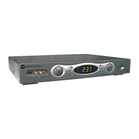
Page 12: Front Panel
FRONT PANEL Displays current channel and program information VIDEO IN USB* VIDEO IN* Connects to Connects to baseband video output of a support devices VCR, camcorder, or other video device TO TV/VCR Connects to TV or VCR CABLE IN Connects to cable signal from your service provider TV/VCR Enables DCT* to control a VCR... -
Page 13: Back Panel
A/B Indicator Lights, if optional switch is activated SELECT switch Selects menu options GUIDE switch Displays the program guide A/B switch Manually enables RF bypass function (optional) GUIDE REMOTE SELEC T REMOTE indicator Lights to indicate remote control is in use Display Displays channel number and time of day... -
Page 14: Basic Operation
BASIC OPERATION Turning Power On and Off POWER Press on the front panel to turn the DCT* on or off. When using the remote control, be sure it is in cable mode by pressing POWER before pressing Changing Channels You can change channels in two ways: CHANNEL Press + or - on the remote control to step through the... -
Page 15: Audio/Video Connections
AUDIO/VIDEO CONNECTIONS Before you move or change components on your entertainment system, review the following: For basic cable connections, use 75-ohm coaxial cables equipped with F-type connectors. A 6-foot coaxial cable is provided to connect the DCT* to your cable wall outlet. A 6-foot component video cable and left/right audio cables are also provided to connect the DCT* to your TV. -
Page 16: Rf Bypass
RF BYPASS oc=ETR=çÜãF ÅçååÉÅíáçå a`qSOMMLa`qSOMU VIDEO ETHERNET SPDIF AUDIO IN TV/VCR RPT OUT IEEE 1394 DVI-D OUT S-VIDEO RF IN RF IN AUDIO OUT OPTICAL Pass Card SPDIF CONV CONV CABLE TV/VCR CABLE From cable outlet To TV... - Page 17 DCT6200/DCT6208 User Guide The DCT* may be equipped with an optional RF Bypass switch. When the optional RF bypass switch is activated, it routes the cable signal directly to a cable-ready TV, bypassing the DCT*. This configuration enables you to view clear (unscrambled) analog programming on the direct cable signal should the DCT* be powered off.
-
Page 18: Optimizing Your Dct* Output Settings
OPTIMIZING YOUR DCT* OUTPUT SETTINGS The Motorola DCT* delivers high-quality video for high definition TVs using the YPbPr (component) and DVI-D video connectors. This section describes how to use the on-screen display to set your DCT* to automatically optimize both standard and high definition video based on your HDTV and personal preferences. - Page 19 DCT6200/DCT6208 User Guide The DVI/YPbPr OUTPUT setting displays as YPbPr OUTPUT if you are not using the DVI video connection. The user settings will also be displayed on the front panel LED whether your TV is off or on. If the on-screen display menu does not appear on your HDTV screen, your TV may not support the default video output setting.
-
Page 20: User Options
User Options Setting Description TV Type Selects the type of TV. The LED panel will display the output type you have selected. Defaults to 16:9. Options are 16:9 (for wide screen TVs); 4:3 LETTERBOX or 4:3 PAN/SCAN (for normal TVs). 4:3 LETTERBOX allows you to view widescreen programming in a letterbox format through the S-video, composite video, or RF video outputs when the DCT* is tuned to a widescreen... - Page 21 Setting Description 4:3 Override Selects the DVI or YPbPr (Component video) output format of the DCT* when it is tuned to 4:3 standard definition programs. Defaults to 480i. Options are OFF, 480i or 480p. If the DVI/YPbPr Output is set to 480i, this setting becomes redundant and defaults to OFF.
- Page 22 Setting Description Back- Selects the background color for closed captions. Defaults ground to AUTO. Color Options are AUTO, WHITE, BLACK, RED, GREEN, BLUE, YELLOW, MAGENTA, or CYAN. Back- Selects the background opacity for closed captions. Defaults ground to AUTO. Opacity Options are AUTO, TRANSPARENT, TRANSLUCENT, SOLID, or FLASHING.
-
Page 23: Connecting Your Dct
CONNECTING YOUR DCT* This section describes how to connect the DCT* to your home entertainment system. Instructions and diagrams are included for the following connections to the DCT*: High Definition Television (HDTV) A/V Receiver – Audio Stereo TV Stereo TV and Stereo VCR A/V Receiver, TV, and VCR Stereo TV, VCR, and DVD In this User Guide, DCT* refers to both the DCT6200 and DCT6208 High... -
Page 24: Connecting Your Dct* To A Hdtv - Video Only
CONNECTING YOUR DCT* TO A HDTV – VIDEO ONLY `çãéçåÉåí=îáÇÉç ÅçååÉÅíáçå ÅçååÉÅíáçå TV/VCR CABLE `~ÄäÉ= áå DVI-HDTV CABLE/ ANTENNA IN VIDEO ETHERNET SPDIF AUDIO IN DVI-D OUT AUDIO OUT Pass Card báíÜÉê=L=çê eaqs Component Video Input a`qSOMMLa`qSOMU IEEE 1394 S-VIDEO OPTICAL SPDIF... - Page 25 Connecting HDTV – Video Only Connect an RF coaxial cable to the cable wall outlet and the CABLE IN connector on the DCT*. Connect the component video cables to the Y, Pb, and Pr connectors on your HDTV and DCT*. Connect a DVI cable to the HDTV connector on your TV.
-
Page 26: Connecting Your Dct* To A Hdtv - Audio Only
CONNECTING YOUR DCT* TO A HDTV – AUDIO ONLY ^ìÇáç ÅçååÉÅíáçå a`qSOMMLa`qSOMU VIDEO ETHERNET SPDIF AUDIO IN TV/VCR IEEE 1394 DVI-D OUT S-VIDEO CABLE AUDIO OUT OPTICAL Pass Card SPDIF eaqs INPUT S-VIDEO VIDEO AUDIO LEFT CABLE/ ANTENNA IN AUDIO RIGHT... - Page 27 Connecting HDTV – Audio Only Connect the stereo audio cable to the the DCT* and the HDTV. For information on configuring your DCT* settings, see “Optimizing Your DCT* Output Settings”. DCT6200/DCT6208 User Guide AUDIO R AUDIO LEFT AUDIO RIGHT connectors on connectors on the...
-
Page 28: Connecting Your Dct* To An A/V Receiver - Audio Only
CONNECTING YOUR DCT* TO AN A/V RECEIVER – AUDIO ONLY ^ìÇáç aáÖáí~ä=~ìÇáç ÅçååÉÅíáçå ÅçååÉÅíáçå TV/VCR CABLE AUDIO VIDEO VIDEO S-VIDEO CABLE/TV VIDEO 2 léíáÅ~ä ÅçååÉÅíáçå VIDEO ETHERNET SPDIF AUDIO IN DVI-D OUT AUDIO OUT Pass Card báíÜÉê=L=çê DIGITAL INPUT COAX OPTICAL TV/MONITOR SPEAKER... - Page 29 Connecting an A/V Receiver – Audio Only There are three options available for audio connections to your A/V receiver: OPTICAL SPDIF Optical ( SPDIF Coaxial ( AUDIO R Stereo audio ( If your equipment supports it, the optical ( SPDIF ) audio outputs may be used in place of the stereo audio outputs AUDIO R and L).
-
Page 30: Connecting Your Dct* To A Stereo Tv
CONNECTING YOUR DCT* TO A STEREO TV oc=ETR=çÜãF pJsáÇÉç sáÇÉç ^ìÇáç ÅçååÉÅíáçå =ÅçååÉÅíáçå ÅçååÉÅíáçå ÅçååÉÅíáçå a`qSOMMLa`qSOMU VIDEO ETHERNET SPDIF AUDIO IN TV/VCR IEEE 1394 DVI-D OUT S-VIDEO CABLE AUDIO OUT OPTICAL Pass Card SPDIF `~ÄäÉ= áå báíÜÉê=L=çê píÉêÉç=qs báíÜÉê=L=çê INPUT S-VIDEO VIDEO AUDIO LEFT... - Page 31 Connecting a Stereo TV Connect an RF coaxial cable to the cable wall outlet and the CABLE IN connector on the DCT*. Connect a second RF coaxial cable to the the DCT* and the Connect the stereo audio cable to the the DCT* and the stereo TV.
-
Page 32: Connecting Your Dct* To A Stereo Tv And Stereo Vcr
CONNECTING YOUR DCT* TO A STEREO TV AND STEREO VCR oc=ETR=çÜãF sáÇÉç ÅçååÉÅíáçå ÅçååÉÅíáçå ETHERNET TV/VCR CABLE `~ÄäÉ=áå píÉêÉç=s`o INPUT CABLE/ AUDIO VIDEO ANTENNA IN To TV ^ìÇáç ÅçååÉÅíáçå VIDEO SPDIF AUDIO IN DVI-D OUT S-VIDEO AUDIO OUT Pass Card OUTPUT AUDIO VIDEO... - Page 33 Connecting a Stereo TV and Stereo VCR Connect an RF coaxial cable to the cable wall outlet and the CABLE IN connector on the DCT*. Connect a stereo audio cable to the on the DCT* and the VCR. Connect a video cable to the INPUT VIDEO Connect a stereo audio cable to the connectors on the Stereo VCR and the...
-
Page 34: Connecting Your Dct* To An A/V Receiver, Tv, And Vcr
CONNECTING YOUR DCT* TO AN A/V RECEIVER, TV, AND VCR oc=ETR=çÜãF sáÇÉç ÅçååÉÅíáçå ÅçååÉÅíáçå TV/VCR CABLE `~ÄäÉ= áå INPUT CABLE/ AUDIO VIDEO ANTENNA IN To TV ^ìÇáç aáÖáí~ä=~ìÇáç ÅçååÉÅíáçå ÅçååÉÅíáçå VIDEO ETHERNET SPDIF AUDIO IN DVI-D OUT S-VIDEO AUDIO OUT Pass Card píÉêÉç=s`o OUTPUT... - Page 35 Connecting an A/V Receiver, TV, and VCR Connect an RF coaxial cable to the cable wall outlet and the CABLE IN connector on the DCT*. Connect a stereo audio cable to the on the DCT* and the Connect a video cable to the CABLE TV VIDEO Connect a stereo audio cable to the...
-
Page 36: Connecting Your Dct* To A Stereo Tv, Vcr, And Dvd
CONNECTING YOUR DCT* TO A STEREO TV, VCR, AND DVD oc=ETR=çÜãF pJsáÇÉç ÅçååÉÅíáçå =ÅçååÉÅíáçå ETHERNET TV/VCR CABLE `~ÄäÉ= áå INPUT CABLE/ AUDIO VIDEO ANTENNA IN To TV sáÇÉç ÅçååÉÅíáçå VIDEO SPDIF AUDIO IN DVI-D OUT S-VIDEO AUDIO OUT OPTICAL Pass Card OUTPUT AUDIO VIDEO... - Page 37 Connecting a Stereo TV, VCR, and DVD This cable configuration may be used for a mono or stereo VCR, because the VCR audio and video jacks are not used. If your TV supports multiple sets of video and audio inputs (such as VID1, VID2, etc.), see the diagram Connecting a Stereo TV and Stereo VCR to connect your DCT*, VCR and TV.
-
Page 38: Recording Your Connections
RECORDING YOUR CONNECTIONS Use this diagram to record connections between your home entertainment components. Later, you can use this diagram to reconnect your system if you move the equipment or add new equipment. Disconnect the power from the DCT* before connecting or changing cable connections. - Page 39 TV/VCR CABLE INPUT CABLE/ AUDIO VIDEO ANTENNA IN To TV píÉêÉç=êÉÅÉáîÉê CD IN AUX IN TAPE 1 CABLE/TV VIDEO 2 DCT6200/DCT6208 User Guide VIDEO ETHERNET SPDIF AUDIO IN DVI-D OUT AUDIO OUT Pass Card OUTPUT AUDIO VIDEO CABLE/ ANTENNA IN SPEAKER CONNECTORS COAX...
-
Page 40: Graphics Overlaying The Video
GRAPHICS OVERLAYING THE VIDEO The DCT* can generate graphics that overlay the video programming or fill the entire television screen. Common examples include on-screen menus (such as the User Setting menu), closed captions, and interactive program guides. The DCT* overlays these graphics whenever you open a menu, enables closed captions, or scrolls through a program grid. -
Page 41: Data Devices
DCT6200/DCT6208 User Guide DATA DEVICES a`qSOMMLa`qSOMU VIDEO ETHERNET SPDIF AUDIO IN TV/VCR IEEE 1394 DVI-D OUT S-VIDEO CABLE AUDIO OUT OPTICAL Pass Card SPDIF Audio/Video devices devices Do not attempt to connect data devices without contacting your service provider. Advanced data features require the proper application and network infrastructure to operate. -
Page 42: Data Features
Data Features In addition to high quality audio and video, the DCT* has the capability to deliver high-speed data services such as Internet access, e-mail, IP Telephony, E-Commerce and home banking. Your DCT* may be equipped with the interface connections illustrated, but their functionality depends on the services offered by your service provider. -
Page 43: Troubleshooting
TROUBLESHOOTING Before calling your service provider, review this troubleshooting guide. This information is to help you quickly solve a problem. If your problem still exists, contact your service provider. Problem Possible Solution The DCT* will not Verify that the AC power cord is connected to the DCT* power on and an AC outlet. - Page 44 Problem Possible Solution There is no audio Verify that the when viewing cable control has not been pressed. Press channels control to restore sound. If the DCT* audio output is connected to the TV, verify that the If the DCT* audio output is connected to a home theater receiver, verify that the receiver is set to the appropriate input source and the mute button on the receiver has not been pressed.
- Page 45 Problem Possible Solution There is no video Verify that the TV is powered on and set to the on the TV screen appropriate input source for the DCT*. Verify that the DCT* is powered on and tuned to an authorized cable channel. Verify that the coaxial cable feed is firmly connected to the DCT* and the wall jack.
- Page 46 Problem Possible Solution There are black Wide screen TVs display 4:3 programs in this format bars to the right unless set to Stretch. Turn on the 4:3 OVERRIDE feature and left of the in the User Settings menu. This enables most wide picture screen TVs to stretch the video to fill the screen (see the TV manual for information about stretching 4:3 video).
- Page 47 Problem Possible Solution There are black This may occur on a 4:3 TV if the 4:3 OVERRIDE setting bars on all four is OFF. To cause 4:3 SD programming to fill the screen, sides of the picture depending on the capabilities of the TV, set 4:3 OVERRIDE to 480i or 480p.
-
Page 48: Specifications
SPECIFICATIONS Physical Dimensions Size 17.13 in. Weight 9.5 pounds 12.75 in. 2.75 in. - Page 49 Visit our website at: www.motorola.com 512443-001 12/03 MGBI...