
Related Manuals for Makita XRT02


Summary of Contents for Makita XRT02
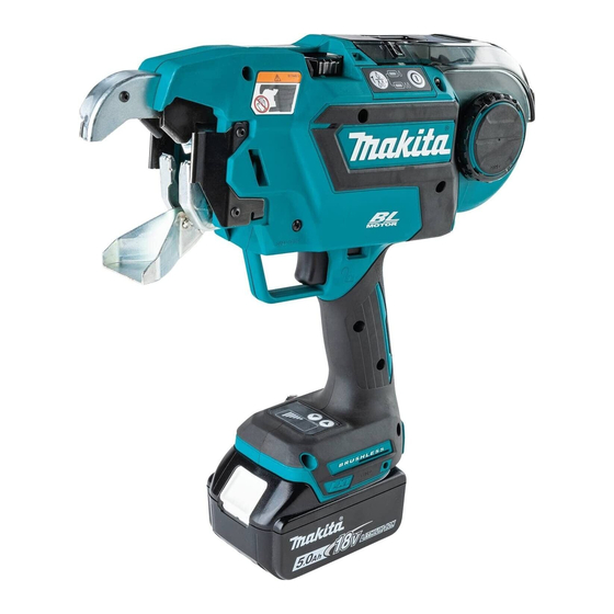
- Page 1 INSTRUCTION MANUAL MANUAL DE INSTRUCCIONES Cordless Rebar Tying Tool Amarradora Inalámbrica de Varilla XRT02 IMPORTANT: Read Before Using. IMPORTANTE: Lea antes de usar.
-
Page 2: Specifications
ENGLISH (Original instructions) SPECIFICATIONS Model: XRT02 Tie wire (Optional accessory) Annealing iron tie wire ø0.8 mm (21GA) Poly coated tie wire ø0.9 mm (20GA) Galvanized tie wire ø0.8 mm (21GA) Approximate number of ties Annealing iron tie wire Approximately 75 ties... -
Page 3: General Power Tool Safety Warnings
Combination of 3 rebars #3 x #3 #4 x #4 #5 x #5 (10 mm x 10 mm) (13 mm x 13 mm) (16 mm x 16 mm) #3 (10 mm) #4 (13 mm) #5 (16 mm) #6 (19 mm) #7 (22 mm) #8 (25 mm) The combination is not designed for high tying strength. - Page 4 Use personal protective equipment. Always Keep cutting tools sharp and clean. Properly wear eye protection. Protective equipment such maintained cutting tools with sharp cutting edges as dust mask, non-skid safety shoes, hard hat, or are less likely to bind and are easier to control. hearing protection used for appropriate conditions Use the power tool, accessories and tool bits will reduce personal injuries.
- Page 5 Otherwise, an accident may occur. Do not bring your hands close to the tying 23. Always use Makita's genuine wires. If wires are point during the wire tying process. Otherwise, not used for a long period of time, they may you may get caught in the wire and injured.
- Page 6 Do not short the battery cartridge: causing fires, personal injury and damage. It will Do not touch the terminals with any con- also void the Makita warranty for the Makita tool and ductive material. charger. Avoid storing battery cartridge in a con-...
-
Page 7: Functional Description
Indicating the remaining battery capacity FUNCTIONAL DESCRIPTION Only for battery cartridges with the indicator CAUTION: Always be sure that the tool is switched off and the battery cartridge is removed before adjusting or checking function on the tool. Installing or removing battery cartridge CAUTION: Always switch off the tool before... -
Page 8: Overheat Protection
Overheat protection NOTE: The tool has an auto power-off function. If the switch trigger is not pulled for 10 minutes, the tool When the tool or battery is overheated, the tool stops is automatically turned off to reduce battery power automatically and the corresponding error number is consumption. - Page 9 Failure to do so may cause an accident. NOTICE: Using wires other than Makita's genu- ine tie wires may cause the tool to malfunction. Fig.7 You can set the tying strength by adjusting the tying strength Push the release lever, and lock it with the lock adjusting button.
- Page 10 Open the reel cover. Make the tip of the wire straight, and pass the wire through the guide. Fig.11 Fig.14 ► 1. Reel cover ► 1. Guide Mount the wire reel on the tool in the orientation shown in the figure. NOTE: If the tip of the wire is bent when it is passed through the guide, the wire may become jammed in the tool.
- Page 11 Rewind the wire to eliminate its slack. Fig.16 Release the lock lever. The release lever returns, and the wire is held by the left and right gears. Fig.18 ► 1. Gear 2. Path of the wire 3. Wire NOTICE: When the lock lever is released and when the left and right gears mesh with each other, the grooves in the gears form a space.
- Page 12 Pull the contact plate cover up in the direction of the Replacing wire guide B arrow and remove it. Bolt B will be removed at the same time. Optional accessory The wire guide B (in silver color) in the arm can be replaced with an optional wire guide B (EG) (in black color) according to the type of tying wire to use.
- Page 13 Align the pipe of the tool with the groove inside the Fix the optional wire guide B (EG) (black) and con- optional wire guide B (EG) (black), and assemble them. tact plate cover securely by tightening bolt A and bolt B. Fig.25 Fig.28 ►...
-
Page 14: Operation
If the tool operates and if no error is shown on the dis- diately. Ask your local Makita Service Center for repairs. play panel, the state of the tool is abnormal. Stop using... -
Page 15: Preparation Before Work
Release the trigger lock. Tying work CAUTION: Before inserting the battery car- tridge, be sure to release your fingers from the switch trigger and lock the trigger. If you insert the battery cartridge while the switch trigger is being pulled, it may cause an accident if the wire tying process is accidentally carried out. - Page 16 Continuous actuation mode After tying, be careful not to hook the arm on the rebars, and then pull the tool up. Switch the tool mode from the single actuation mode to the continuous actuation mode using the mode switching button. Fig.36 Fig.38 ►...
- Page 17 After tying, be careful not to hook the arm on the • Tie the wire onto the flat (with no unevenness) rebars, and then pull the tool up. sections of crossed rebars. Fig.42 • If tying strength is insufficient, change the tying Fig.40 orientation and perform tying twice so that tying strength increases.
-
Page 18: Maintenance
When inserting the wire brush, hold it short and push it into the guide little by little. To maintain product SAFETY and RELIABILITY, repairs, any other maintenance or adjustment should be performed by Makita Authorized or Factory Service Centers, always using Makita replacement parts. Fig.47 ► 1. Wire brush... -
Page 19: Disassembling And Cleaning
Using the air duster gun Open the reel cover, push the release lever, and lock it with the lock lever. Then bring the air duster gun close to the guide and blow the air. Make sure the air comes from the tip of the arm. Fig.48 ►... - Page 20 Turn wire guide B over and clean its inside. Fig.53 ► 1. Bolt A 2. Bolt B 3. Contact plate cover 4. Wire guide B Fig.56 Remove top plate, cutter B, link arm A and cutter A NOTICE: Do not forcibly remove any bolts that from arm plate A.
- Page 21 Install cutter B and the top plate onto arm plate A. Install the contact plate cover in the direction of (Install cutter B on cutter A and link arm A.) the arrow. Fig.59 Fig.62 ► 1. Cutter B 2. Top plate 3. Arm plate A 4. Cutter A ►...
- Page 22 If an error occurs, an error tone will sound, and an error number will be shown on the display panel. Refer to the following table and take appropriate actions. If the error persists, ask Makita Authorized Service Centers for repairs.
-
Page 23: Optional Accessories
OPTIONAL ACCESSORIES CAUTION: These accessories or attachments are recommended for use with your Makita tool specified in this manual. The use of any other accessories or attachments might present a risk of injury to persons. Only use accessory or attachment for its stated purpose. -
Page 24: Especificaciones
ESPAÑOL (Instrucciones originales) ESPECIFICACIONES Modelo: XRT02 Alambre de amarre Alambre de amarre de hierro recocido ø0,8 mm (21GA) (accesorio opcional) Alambre de amarre recubierto ø0,9 mm (20GA) con resina de poliéster Alambre de amarre galvanizado ø0,8 mm (21GA) Número aproximado de ama-... -
Page 25: Advertencias Generales De Seguridad Para Herramientas Eléctricas
Combinación de 3 varillas #3 x #3 #4 x #4 #5 x #5 (10 mm x 10 mm) (13 mm x 13 mm) (16 mm x 16 mm) #3 (10 mm) #4 (13 mm) #5 (16 mm) #6 (19 mm) #7 (22 mm) #8 (25 mm) La combinación no está... - Page 26 Si no es posible evitar usar una herramienta Utilice siempre gafas protectoras para prote- eléctrica en condiciones húmedas, utilice un ger sus ojos de lesiones al usar herramientas alimentador protegido con interruptor de cir- eléctricas. Las gafas deben cumplir con la cuito de falla a tierra (ICFT).
- Page 27 Solicite la repara- accidentalmente, enjuague con agua. Si hay ción en el centro de servicio Makita de su loca- contacto del líquido con los ojos, busque asis- lidad. Si la herramienta se utiliza en un estado tencia médica.
- Page 28 No desarme ni modifique el cartucho de bate- la indicación de error. (Solicite la reparación en ría. Podría ocurrir un incendio, calor excesivo o el centro de servicio Makita de su localidad). una explosión. • Cuando cargue o descargue un carrete de Si el tiempo de operación se ha acortado en...
-
Page 29: Descripción Del Funcionamiento
► 1. Indicador rojo 2. Botón 3. Cartucho de batería lesiones personales y daños. Asimismo, esto inva- lidará la garantía de Makita para la herramienta y el Para quitar el cartucho de batería, deslícelo de la herra- cargador Makita. -
Page 30: Protección Contra Sobrecarga
Protección contra sobrecarga Indicación de la capacidad restante de la batería Cuando la herramienta o batería sean utilizadas de una manera que consuma una cantidad anormalmente alta de corriente, la herramienta se detendrá automática- Únicamente para cartuchos de batería con el mente y el número de error correspondiente se visuali- indicador zará... - Page 31 Al presionar el botón de encendido/apagado, la herra- Accionamiento del interruptor mienta se enciende y la luz indicadora de modo de amarre se ilumina. A fin de ajustar su posición inicial, ADVERTENCIA: la herramienta se activa temporalmente. Una vez com- Antes de insertar el car- pletado el ajuste, la herramienta se detiene automáti- tucho de batería en la herramienta, compruebe...
-
Page 32: Montaje
De lo con- trario, se podría ocasionar un accidente. AVISO: Si se usan alambres que no sean los auténticos alambres de amarre de Makita, la herramienta puede funcionar mal. Presione la palanca de liberación y bloquéela con la palanca de bloqueo. - Page 33 Abra la cubierta del carrete. Enderece la punta del alambre y pase el alambre por la guía. Fig.11 Fig.14 ► 1. Cubierta del carrete ► 1. Guía Monte el carrete de alambre en la herramienta según la orientación que se muestra en la figura. NOTA: Si la punta del alambre está...
- Page 34 Rebobine el alambre para tensarlo. Fig.16 Libere la palanca de bloqueo. La palanca de liberación regresa a su posición, y el alambre queda sujetado por los engranajes izquierdo y derecho. Fig.18 ► 1. Engranaje 2. Ruta del alambre 3. Alambre AVISO: Cuando se suelta la palanca de bloqueo y los engranajes izquierdo y derecho se engranan...
- Page 35 Jale de la cubierta de la placa de contacto hacia Reemplazo de la guía de alambre B arriba en la dirección de la flecha y retírela. El perno B se extraerá al mismo tiempo. Accesorio opcional La guía de alambre B (en color plata) en el brazo de la herramienta se puede reemplazar con una guía de alambre B opcional (EG) (en color negro) según el tipo de alambre de amarre a utilizar.
- Page 36 Reemplace la guía de alambre B equipada de Instale la cubierta de la placa de contacto en la serie (en color plata) con una guía de alambre B opcio- dirección de la flecha. nal (EG) (en color negro). Fig.27 Fig.24 ►...
-
Page 37: Operación
► 1. Guía de volutas mienta inmediatamente. Solicite la reparación en el centro de servicio Makita de su localidad. Verificación de la detección de apertura/ Verificación del seguro del gatillo cierre de la guía de volutas Retire el alambre de amarre, verifique la operación... - Page 38 Preparación antes del trabajo PRECAUCIÓN: Si abre la guía de volutas y conecta la alimentación para comprobar el bloqueo de Asegúrese de que el cartucho de batería haya seguridad, sujete la guía de volutas como se muestra sido extraído y de que el gatillo está bloqueado. en la figura.
- Page 39 Modo de accionamiento continuo Jale el gatillo interruptor una vez. El alambre se alimenta y se corta Conmute el modo de la herramienta desde el automáticamente. modo de accionamiento simple al modo de acciona- El gancho sujeta y retuerce el alambre, y luego miento continuo mediante el botón de conmutación de retorna a su posición original una vez que los alambres modo.
- Page 40 Después del amarre, tenga cuidado de no engan- • Ate el alambre sobre las secciones planas (sin char el brazo de la herramienta en las varillas, y luego irregularidades) de las varillas cruzadas. jale de la herramienta hacia arriba. Fig.42 •...
-
Page 41: Mantenimiento
Para mantener la SEGURIDAD y FIABILIDAD del pro- ducto, las reparaciones, y cualquier otra tarea de man- tenimiento o ajuste deberán ser realizadas en centros de servicio autorizados o de fábrica Makita, empleando siempre repuestos Makita. Fig.47 ► 1. Cepillo de alambre... - Page 42 Uso de la pistola sacudidora de aire Abra la cubierta del carrete, presione la palanca de libe- ración y bloquéela con la palanca de bloqueo. Luego, acerque la pistola sacudidora de aire a la guía y sople aire. Asegúrese de que el aire salga por la punta del brazo de la herramienta.
- Page 43 Retire el perno A y extraiga la guía de alambre B. Fig.53 ► 1. Perno A 2. Perno B 3. Cubierta de la placa de contacto 4. Guía de alambre B AVISO: No extraiga a la fuerza ningún perno que no pueda extraerse con la llave hexagonal.
- Page 44 Montaje Acople la guía de alambre B apretando temporal- mente el perno A. Una vez terminada la limpieza, monte las piezas siguiendo el procedimiento a continuación. Instale la cortadora A y el brazo articulado A de manera que se ajusten a la forma de la placa de brazo A. Fig.61 ►...
- Page 45 Después del montaje, verifique que la placa de contacto puede moverse tal como se muestra en la figura. Fig.64 ► 1. Placa de contacto NOTA: Si la placa de contacto ha quedado pillada, presiónela como se muestra en la figura. Fig.65 45 ESPAÑOL...
-
Page 46: Accesorios Opcionales
Si se produce un error, sonará un tono de error y se visualizará un número de error en el panel indicador. Consulte la tabla siguiente y tome las medidas apropiadas. Si el error persiste, pida a su centro de servicio autorizado de Makita que se lo repare. - Page 48 Para reducir la exposición a estos productos químicos: trabaje en un área bien ventilada y póngase el equipo de seguridad indicado, tal como las máscaras contra polvo que están especialmente diseñadas para filtrar partículas microscópicas. Makita Corporation 3-11-8, Sumiyoshi-cho, Anjo, Aichi 446-8502 Japan 885876-941...