Honeywell OELD Operating Instructions Manual
Smart junction box
Hide thumbs
Also See for OELD:
- Quick start manual (12 pages) ,
- Operating instructions manual (37 pages)
Table of Contents
Advertisement
Quick Links
Advertisement
Table of Contents

Related Manuals for Honeywell OELD


Summary of Contents for Honeywell OELD
- Page 1 Operating Instructions OELD Smart Junction Box (3018M5000_1-3)
-
Page 2: Table Of Contents
6.1 LCD ..............................16 6.1.1 Start-up ........................... 16 6.1.2 Normal Operation ........................17 6.1.3 Display Screen ........................17 6.2 BLE Communication (Optional)...................... 18 6.3 Alternative communications (SHC-1) ..................... 18 7. OELD Mobile App ..........................20 7.1 Install mobile App ........................... 20... - Page 3 OELD User Manual (3018M5000_1-3) Revision 1, Issue 3 7.2 Run OELD Mobile App ........................20 8. Maintenance ............................24 8.1 General ............................24 8.2 Display Module Replacement ......................24 9. Faults and Warning ..........................25 10 Specifications ............................26 11. Ordering Information ........................... 28...
-
Page 4: Safety
6. Access to the interior of the product, when carrying out any work, must be conducted only by trained personnel. 7. Do not use the OELD LCD backlit status indication for safety-related purposes. 8. In order to maintain electrical safety, the unit must not be operated in atmospheres of more than 21% oxygen. -
Page 5: Waste Electrical And Electronic Equipment (Weee) Directive
This manual is for use with the OELD junction box only. Honeywell Analytics can take no responsibility for installation and/or use of its equipment if not done so in accordance with the appropriate issue and/or amendment of the Operating Instructions. - Page 6 2) This device must accept any interference, including interference that may cause undesired opera- tion of the device WARNING OELD has been tested and meets applicable limits for radio frequency (RF) exposure. Ac- cording to the RF Exposure report, minimum 20 cm separate distance is required.
-
Page 7: Overview
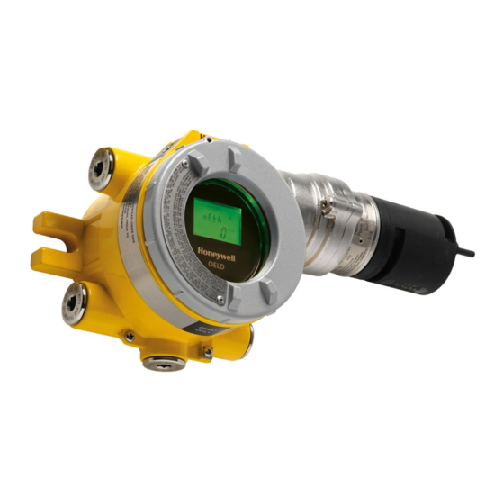
2 Overview 2.1 Introduction OELD is an ATEX certified Ex d junction box for use with sensors that feature a 4-20mA output. The sensor is Searchpoint Optima Plus or Searchline Excel. It provides a local visual status indication, and a Bluetooth low energy interface for remote monitoring and configuration using mobile device. OELD is ATEX approved for use in either Zone 1 (gas) or Zone 21 (dust) hazardous areas as well as cULus approved for use in Class I Division 1 or Class II Division 1. - Page 8 OELD User Manual (3018M5000_1-3) Revision 1, Issue 3...
-
Page 9: Optional Accessories
2.2.3 Sunshade (94000-C-1018) An optional sunshade is available which covers the OELD and can extend over either side to also protect a Searchpoint Optima or Searchline Excel The sunshade slots over the OELD mounting bolts so no additional fixings are required. -
Page 10: Installation
3.2 Mechanical Installation The OELD can be mounted in a number of ways using the integral mounting tabs. The OELD can be attached to flat wall surfaces or to Unistrut®. With the optional Pipe Mount kit, the unit can be mount- ed to pipe of diameter 2”... -
Page 11: Optional Pipe And Celling Mount Installation
3.2.2 Optional pipe and celling mount installation OELD may be fixed to a vertical pipe of 50 to 150 mm (2 to 6 inches) in diameter using the optional Pipe Mounting Bracket. The pipe mounting bracket kit (1226A0358) consists of one bracket, two sets of carriage bolts, nuts and lock washers. -
Page 12: Electrical Installation
OELD User Manual (3018M5000_1-3) Revision 1, Issue 3 3.3 Electrical Installation 1. Remove the lid. 2. Lift the handle and take out the internal display module. 3. Fit a suitable approved Ex d cable gland to the required cable entry for the field cable. -
Page 13: Electrical Connections
485B Orange Reserved for SHC-1 Note: OELD is reverse polarity protected. Spare conductors must be terminated in a spare terminal. Wiring must be in accordance with local, national and/or company regulations. Bare conductors must be avoided. Refer to individual sensor manuals for sensor wiring details. Specific wiring diagrams for some com- monly used sensors are provided in the Appendix. -
Page 14: Power Supply
Revision 1, Issue 3 4.1 Power Supply OELD requires an isolated voltage supply of 18 - 32 Vdc (nominal 24 Vdc), which is suitably approved for the region (for example, UL approved). Power consumption is 2 W maximum. Refer to individual sensor manuals for sensor specific limits and power consumption. -
Page 15: Earth Regimes
• Field cable screens should be connected to instrument earth at the control room. The other end of the field cable screen may be terminated in a spare terminal of OELD. It should not be connected to the continuity plate. -
Page 16: Configuration
1. Threshold for local alarm indication The gas reading at which OELD indicates an alarm (flashing red lights) can be set between 10 and 65 %FSD. The default setting is 20 %FSD. Note: This setting is local to OELD and applies only to the red lights in the OELD backlit. Changing the level will have no effect on alarm levels configured in the sensor, or in the control room. -
Page 17: Configuration Process
To configure OELD, it should be connected to mobile device over Bluetooth Low Energy first. The blue backlit of OELD will flash when a mobile device pairs with OELD so that an operator can easily find out and identify the target OELD. When OELD is connected to mobile device successfully the blue backlight will stay on in normal condition. -
Page 18: Operation
LCD and backlit test. During LCD test each segment of LCD will be on one by one while LCD backlit will flash in various colors. And OELD shows software version and various configuration information as below. During start-up sequence except LCD test, the green light will be on. -
Page 19: Normal Operation
-40 °C. The display is not damaged and recovers when the temperature increas- Note: The refresh rate of OELD display will change up to 6 seconds at lower temperature so that LCD readability at lower temperature can be maintained... -
Page 20: Ble Communication (Optional)
Refer to the Mobile device user’s manual for details of how to use the Bluetooth on the mobile device. Note: OELD is compatible with the BLE Point-to-Point mode of operation only. If OELD is connected with one mobile device, it won’t be scanned by other mobile device... - Page 21 OELD User Manual (3018M5000_1-3) Revision 1, Issue 3 Note: OELD does not support XPIS terminal. If XPIS terminal is required, an appropriate junction box should be used instead WARNING Do not use BLE communication when the SHC1 Handheld Interrogator is connected to RS485 terminal on the OELD Refer to the individual sensor manual for details of how to use the SHC1 Handheld Interrogator.
-
Page 22: Oeld Mobile App
7. OELD Mobile App 7.1 Install mobile App Mobile App on the mobile device is used to configure OELD and sensor connected to an OELD. The OELD configuration is done as part of sensor configuration by mobile app. The sensor considers an OELD as local display accessory with BLE. - Page 23 OELD User Manual (3018M5000_1-3) Revision 1, Issue 3...
- Page 24 Green LED in normal Off or on *Note Alarm threshold and trigger is for local indication at OELD. They do not affect the operation of con- nected sensor and other alarm devices. 7.4 Configure Optima Plus OELD mobile helps a user to configure Optima Plus connected to OELD. The configurable parame- ters are as shown in the table below.
- Page 25 Revision 1, Issue 3 7.5 Calibrate Optima Plus OELD mobile app allows a user to calibrate the Optima Plus same as SHC1 handheld device. 1. After connecting to OELD device, go to Calibrate menu on the mobile app 2. Click on “Zero” button to start zeroing 3.
-
Page 26: Maintenance
8. Maintenance 8.1 General Periodically inspect OELD and cabling for signs of physical damage. Clean the glass window with a damp cloth. Do not use solvents or abrasive cleaners. OELD has no user serviceable parts. Honeywell Analytics recommend that the unit’s configuration and operation are checked annually. -
Page 27: Faults And Warning
Check the sensor by referring to sensor detector manual Comm Err F-01 Internal Comm. failure Reset OELD. If fault still appears, re- place the display module Curr FLt F-02 Fault level input from the Check the sensor by referring to sensor... -
Page 28: Specifications
Measurement range Visual Green/amber/red/blue multi-colour backlight to display for indication of detector indication and OELD status. Green (normal) indication can be disabled via app. Power supply 18 to 32 Vdc (24 Vdc nominal), <2 W Interfaces Bluetooth® (BLE) non-intrusive connection to suitable mobile device running the OELD mobile app. - Page 29 OELD User Manual (3018M5000_1-3) Revision 1, Issue 3 Maritime Type approved to DNV, BV , Lloyds , ABS Approvals* EN 60945 (EMC) IEC 60092-504 Other BT SIG (Bluetooth), RED, FCC , country-specific wireless approvals Approvals Bluetooth com- Certificate-based mutual authentication. Encryption to AES128.
-
Page 30: Ordering Information
OELD User Manual (3018M5000_1-3) Revision 1, Issue 3 11. Ordering Information Part Number Description OELD Smart Junction Box, Display, Ex d, Aluminum, 5 x M25 OELDBXXXXXADMAX Cable Entries, Bluetooth, ATEX/IECEx OELD Smart Junction Box, Display, Ex d, Painted 316SST, 5 OELDBXXXXXSDMAX... - Page 31 Toll free: +1 800 538 0363 Fax: +1 847 955 8210 detectgas@honeywell.com www.honeywell.com Asia Pacific Honeywell Analytics Asia Pacific Co., Ltd. Please Note: 7F SangAm IT Tower While every effort has been made to ensure 434 Worldcup Buk-ro, Mapo-gu, accuracy in this publication, no responsibility can be accepted for errors or omissions.