Table of Contents
Advertisement
Quick Links
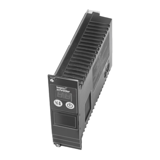
Field bus interface PFA
Module subrack BGT
Technical Information · GB
6 Edition 03.11l
• 19" module for easy transmission of activation signals and
feedbacks from burner control units via fieldbus cable
• Remote maintenance and diagnostics facilities
• Saves installation and wiring costs
• Units can be exchanged during bus mode operation thanks to
industrial plug connector system
• Bus interface remains in operation when PFA is switched off
(standby mode)
• Certification for PROFIBUS DP
Industrial & Commercial Thermal
Advertisement
Table of Contents

Related Manuals for Honeywell PFA 700


Summary of Contents for Honeywell PFA 700
-
Page 1: Module Subrack Bgt
Industrial & Commercial Thermal Field bus interface PFA Module subrack BGT Technical Information · GB 6 Edition 03.11l • 19" module for easy transmission of activation signals and feedbacks from burner control units via fieldbus cable • Remote maintenance and diagnostics facilities • Saves installation and wiring costs • Units can be exchanged during bus mode operation thanks to industrial plug connector system... -
Page 2: Table Of Contents
3.9 Fault signalling........13 8.1 PFA 700, PFA 710....... . .25 3.10 Connection diagrams . -
Page 3: Application
The use of a standard bus system offers massive ben- In module subrack BGT, up to nine burner control units can be inserted together with the PFA 700, while with the PFA 710, efits compared to manufacturer-specific bespoke solu- the maximum is eight burner control units. - Page 4 For interworking of up to nine burner control units PFU 760 for directly ignited burners to communication net- works using PROFIBUS DP. The PFA 700 is plugged into the module subrack with printed-circuit board and rear terminal strip, together with the burner control units.
-
Page 5: Examples Of Application
Application 1 .1 Examples of application 1 .1 .2 PFA 700 with PFU 760L, staged High/Low burner control 1 .1 .1 PFA 700 with PFU 760, staged On/Off burner control L1, N, PE L1, N, PE GIK..B VAS..N VR..R VR..R The burner starts at low-fire rate. -
Page 6: Pfa 710 With Pfu 780, Stage-Controlled Main Burner With Alternating Pilot Burner
Application 1 .1 .3 PFA 710 with PFU 780, stage-controlled main 1 .1 .4 PFA 710 with PFU 780, stage-controlled main burner with alternating pilot burner burner with permanent pilot burner L1, N, PE L1, N, PE 02–04 06–08 06–08 ϑ1 02–04 06–08 02–04... -
Page 7: Certification
Certification 2 Certification 2 .1 EC type-tested and certified – Low Voltage Directive (2006/95/EC) in conjunction with EN 60730, – Electromagnetic Compatibility Directive (2004/108/ EC) in conjunction with the relevant standards relat- ing to radiation. 2 .2 Approval for Russia Certified by Gosstandart under Technical Regulations. -
Page 8: Function
The field bus interface PFA 700 integrates up to nine and heating during operation from the control system burner control units PFU 760 into industrial commu- (PLC) to the PFA. -
Page 9: Air Valve
Function 3 .2 Air valve – DP Masters Class 2 (DPM2) DPM2 devices are programming, project planning or The air valves used to purge the furnace or kiln can ei- operator-control devices. They are used for configu- ther be activated via the PROFIBUS or via a separate ration and commissioning of the system or for system cable (to terminal strip X10 of the BGT –... -
Page 10: Addressing
Function 3 .5 Addressing 3 .6 Network technology A maximum of 126 units (masters and slaves) can be All devices are connected in a bus structure (line). Up connected to a PROFIBUS DP system. Each station is to 32 stations (masters or slaves) can be connected in assigned an individual PROFIBUS address which can a single segment. -
Page 11: Configuration
To allow for simple and standardized planning, the (PFA ▶ master) (master ▶ PFA) parameters of the PFA have been summarized in a so- PFA 700 5 bytes 3 bytes called device master data file (GSD). The file structure PFA 710... - Page 12 Function PFA 700 PFA 710 1, 2 1, 2 1, 2 1, 2 1, 2 1, 2 1, 2 1, 2 1, 2 Input bytes (PFA ▶ master) Input bytes (PFA ▶ master) 1, 2 Byte 0 Byte 1 Byte 2...
-
Page 13: Program Status
Function 3 .8 Program status DISPLAY Program status PFA switched off Programming mode 0.0. (blinking dots) Manual mode Normal operation Profibus fault 3 .9 Fault signalling DISPLAY Fault message (blinking) Bus fault Undervoltage in power pack Bus module fault In manual mode, two dots blink on the display. PFA, BGT ·... -
Page 14: Connection Diagrams
Function 3 .10 Connection diagrams 3 .10 .1 PFA 700 and BGT SA-9U/1DP700 For the explanation of symbols, see page 27 (Legend). BGT SA-9U/1DP700 (8 440 229 1) PROFIBUS DP +24 V 1. PFU 9. PFU 1. PFU 230 V 230 V 9. -
Page 15: Pfa 710 And Bgt Sa-8U/1Dp
Function 3 .10 .2 PFA 710 and BGT SA-8U/1DP For the explanation of symbols, see page 27 (Legend). BGT SA-8U/1DP710 (8 440 229 2) PROFIBUS DP +24 V 1. PFU 8. PFU 1. PFU 7. PFU 8. PFU 1. PFU 230 V 230 V 8. -
Page 16: Flame Control Using An Electrode
Function 3 .10 .3 Flame control using an electrode 3 .10 .5 Flame control with UV sensor for continuous operation UVD 1 X1…9 (BGT SA-9U) X1…8 (BGT SA-8U) X1…9 (BGT SA-9U) X1…8 (BGT SA-8U) 24 V=, 200 mA UVD 1 3 .10 .4 Flame control with UV sensor UVS X1…9 (BGT SA-9U) X1…8 (BGT SA-8U) -
Page 17: Parameters
Parameters 4 Parameters Factory default Description Parameter Value range Adjustable* setting Manual mode limited to 5 minutes 0; 1 Manual operating mode 1; 2; 3; 4 Last fault Pb; 32; bE* – – Second to last occurring fault Pb;... -
Page 18: Scanning The Parameters
Parameters 4 .1 Scanning the parameters 4 .3 Manual operation During operation, the 7-segment display shows the pro- The PFA can be started in manual mode for burner ad- gram status. justment or for fault-finding. The individual parameters of the PFA can be called up When switching on, press the Reset/Information but- on the display by repeatedly pressing the Reset/Infor- ton until the unit reverts to manual mode. -
Page 19: Pfa 700
0.1. 0.3. 0.0. 0.1. 0.3. PFU 760 0× 1× The PFA 700 is programmed at the factory so that volt- 0× 1× 2× 3× 4× 5× age is applied to all burner control units PFU for the start-up signal of all burners and the external air valve Parameter 43 = 4 control. -
Page 20: Pfa 710
Parameters 4 .3 .2 PFA 710 Parameter 43 = 4 Default operating mode parameters PFA 710 with PFU 780L, High/Low operating mode – example of application, see page 6 (PFA 710 with PFU 780, stage- Parameter 43 = 1 controlled main burner with permanent pilot burner). 0.0. -
Page 21: Selection
Field bus interface Slots for: 8 PFU 9 PFU For connecting: PFU 760 /1DP700 1 PFA 700, PROFIBUS DP bus interface PFU 780 /1DP710 1 PFA 710, PROFIBUS DP bus interface Mains voltage: 220/240 V AC 110/120 V AC Special version * If “none”, this specifi... -
Page 22: Project Planning Information
When exchanging the old PFA 700 (Order No. 8 439 6 .1 Installation 510 0) for the new PFA 700, the mains voltage on the The BGT can be installed in any position. new units must be selected in accordance with the ap-... -
Page 23: Wiring
Project planning information 6 .3 Wiring Data cables A and B must not be reversed. The power supply for the bus terminator is provided by Integrate module subracks BGT in the equipotential the PFA. The bus terminator can be connected in the bonding system. -
Page 24: Accessories
To replace existing PROFIBUS plug connectors, if a new The current software can be downloaded from our In- PFA 700 is operated in an old module subrack with the ternet site at Order No. 8 440 228 3, to improve EMC. -
Page 25: Technical Data
Technical data 8 Technical data Operating controls 8 .1 PFA 700, PFA 710 Front width 8 depth units = 40.6 mm. Overall height 3 height units = 128.4 mm. Ambient temperature: -20°C to +60°C. 4 digital inputs: 24 V DC, ± 10%, < 10 mA. -
Page 26: Bgt
Technical data 8 .2 BGT Weight: 2.3 kg. Dimensions PFA, BGT · Edition 03.11l... -
Page 27: Legend
Legend 9 Legend Display Ready for operation Safety interlocks Burner start-up signal Digital input Ignition transformer Gas valve Air valve Purge External air valve control Flame signal Burner operating signal Operating signal, pilot burner Operating signal, main burner Fault signal Reset Input signal Output signal... -
Page 28: Feedback
Feedback Feedback Finally, we are offering you the opportunity to assess this “Technical Information (TI)” and to give us your opinion, so that we can improve our documents further and suit them to your needs. Clarity Comprehension Scope Found information quickly Coherent Too little Searched for a long time...