Honeywell Pro-Watch 6000 Installation Manual
Two-reader module
Hide thumbs
Also See for Pro-Watch 6000:
- Installation manual (19 pages) ,
- Installation manual (21 pages)

Related Manuals for Honeywell Pro-Watch 6000


Summary of Contents for Honeywell Pro-Watch 6000
- Page 1 Pro-Watch 6000 Two-Reader Module (PW6K1R2) Installation Guide July 2010 © 2010 Honeywell International, Inc. All rights reserved. 800-01951, Revision C...
- Page 2 All product and brand names are the service marks, trademarks, registered trademarks, or registered service marks of their respective owners. Printed in the United States of America. Honeywell reserves the right to change any information in this document at any time without prior notice.
-
Page 3: Table Of Contents
ONTENTS Notices Warnings and Cautions ..................v Disclaimer ......................vi Limited Warranty ....................vii Confidentiality ....................vii Compliance ......................viii Unpacking Procedure ..................viii Shipping Instructions ................... ix Installing the PW-6000 Two-Reader Module Description ......................1 Specifications ......................2 Setup........................3 Setting Jumpers.................... - Page 4 www.honeywell.com...
-
Page 5: Notices
DO NOT ACCEPT VERBAL APPROVALS, BECAUSE THEY ARE NOT VALID. Honeywell never recommends using the PW-6000 or related products for use as a primary warning or monitoring system. Primary warning or monitoring systems should always meet local fire and safety code requirements. The installer must also test the system on a regular basis by instructing the end user in appropriate daily testing procedures. -
Page 6: Disclaimer
Customer harmless for any costs or damages including reasonable attorneys' fees which Customer may be required to pay as a result of the defective Product or the negligence of Honeywell, its agents, or its employees. -
Page 7: Limited Warranty
All Products sold or licensed by Honeywell include a warranty registration card which must be completed and returned to Honeywell by or on behalf of the end user in order for Honeywell to provide warranty service, repair, credit or exchange. All warranty... -
Page 8: Compliance
For any additional information regarding the compliance of this product to any EU-specific requirements, please contact: Honeywell Security & Communications Honeywell Security - Quality Assurance Dept., Newhouse Industrial Estate Motherwell Lanarkshire ML1 5SB Scotland United Kingdom Tel: +44)0) 1698 738200 Email: UK64Sales@Honeywell.com... -
Page 9: Shipping Instructions
Notices Shipping Instructions Shipping Instructions To ship equipment back to Honeywell, Inc.: 1. Contact the customer service department at 800-323-4576 before returning equipment. When you call please have available: • A description of the problem or reason you are returning the equipment. - Page 10 Notices Shipping Instructions www.honeywell.com...
-
Page 11: Installing The Pw-6000 Two-Reader Module
Installing the PW-6000 Two-Reader Module Description The PW-6000Two-Reader Module provides support for up to two access control doors by providing connections for Wiegand or Clock/Data type readers, supervised inputs, and relay outputs. You can either mount the board in a rack or open and flat. If you rack-mount the board, only one edge is accessible for wiring;... -
Page 12: Specifications
6 conductors, 18AWG, 500 feet (150m) max. shield and drain Mechanical Dimension 5.5" (140mm) W x 9" (229mm) L x 1" (25mm) H Weight 12 oz. (340g) nominal Environment Temperature 0°C to +49°C, operating, -55°C to +85°C, storage 0% to 85% RHNC Humidity www.honeywell.com... -
Page 13: Setup
Installing the PW-6000 Two-Reader Module Setup Setup Setting Jumpers Table 1: Jumper Settings Jumper Setting Default Selected Port 1 RS-485 EOL terminator is not active Port 1 RS-485 EOL terminator is active Reader 0 Power Terminal provides 5 VDC Reader 0 Power Terminal provides 12 VDC Reader 1 Power Terminal provides 5 VDC... -
Page 14: Setting Dip Switches
ADDRESS 3 ADDRESS 4 ADDRESS 5 ADDRESS 6 ADDRESS 7 ADDRESS 8 ADDRESS 9 ADDRESS 10 ADDRESS 11 ADDRESS 12 ADDRESS 13 ADDRESS 14 ADDRESS 15 ADDRESS 16 ADDRESS 17 ADDRESS 18 ADDRESS 19 ADDRESS 20 ADDRESS 21 ADDRESS 22 www.honeywell.com... - Page 15 Installing the PW-6000 Two-Reader Module Setup Table 2: DIP Switch Settings (continued) Selection ADDRESS 23 ADDRESS 24 ADDRESS 25 ADDRESS 26 ADDRESS 27 ADDRESS 28 ADDRESS 29 ADDRESS 30 ADDRESS 31 Reserved 9,600 BPS 19,200 BPS 38,400 BPS* Not Used* * = Default PW-6000 Two-Reader Module Installation Guide, Document 800-01951, Revision C...
-
Page 16: Led Operation
The input LEDs flash when there is a fault associated with the input. When any relay or input is energized or ON, its corresponding status LED becomes ON also. The LED remains ON for as long as the relay is energized. www.honeywell.com... - Page 17 Installing the PW-6000 Two-Reader Module LED Operation The assignment for each relay status LED is shown in the following table. Table 4: Additional PW6000 Two-Reader Module LEDs LED number Description Reader 0 activity Reader 1 activity Input 0 Input 1 Input 2 Input 3 Input 4...
-
Page 18: Power
TR- terminal. By factory default J1 is set open. If this board is the last board on the RS-485 bus, install jumper J1 across both pins (closed). Closing J1 provides the bus termination required. www.honeywell.com... -
Page 19: Wiring
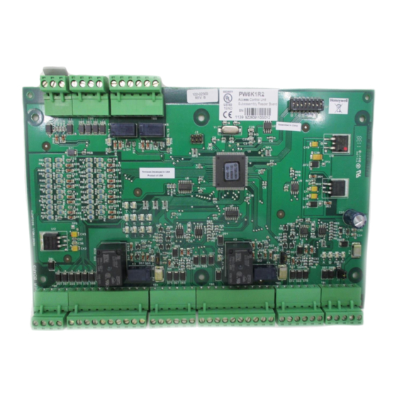
Installing the PW-6000 Two-Reader Module Wiring Wiring This section presents information on reader wiring, input wiring, and control output wiring. The following figure shows the PW-6000 board and identifies its terminal block pin assignments. Figure 1: PW-6000 Two-Reader Module Wiring: Connectors 1-7 Short Door Status TWO READER BOARD... - Page 20 Figure 2: PW-6000 Two-Reader Module Wiring: Connectors 1, 7-9 For RS-485 Communication Connections, twist the blue pair together and use as the common; Note: use the orange pair as your data pair, observing polarity. Connect the external drain shield to the appropriate earth ground on one end. www.honeywell.com...
-
Page 21: Reader Wiring
Installing the PW-6000 Two-Reader Module Wiring Reader Wiring The following Honeywell reader module numbers have been approved by UL for use with the PW6K1R2: OM40BHONA, OM55BHONA, OP10HONE, OP30HONE, OP40HONE, OP90HONE, OT30HONA, OT31HONA, OT35HONA, and OT36HONA. Each reader port supports a reader with TTL interface. Power to the reader is selectable as 5VDC or 12VDC (pass-through). -
Page 22: Input Wiring
The following two circuits are suggested. Locate the protection circuit as close to the load as possible (within 12 inches [30cm]); the effectiveness of the circuit decreases as the distance from the load increases. www.honeywell.com... -
Page 23: Mounting Options
Use sufficiently large gauge of wires for the load current to avoid voltage loss. Mounting Options This board can be mounted on-edge in the rack-mount enclosure provided by Honeywell or it can be mounted flat against any surface using standoffs under the mounting holes provided in each of the four corners of this board. -
Page 24: Installing The Module
7. Connect communications wiring to the Intelligent Controller. 8. Recheck wiring for correct connections and continuity. 9. When all boards have been installed, connect the power supply cord for proper connections and power. 10.Set up the panel controls using the host software. www.honeywell.com... -
Page 25: Pw-6000 2-Reader Input Module Programming Sheet
PW-6000 2-Reader Input Module Programming Sheet Project Name Location / Country Host IC Board Board Description PW Panel RS485 Port Board Address Location Floor Cabinet Location Tamper Input Connected Powerfail Shunted Termination Jumper J1 Not Active PW-6000 Two-Reader Module Installation Guide, Document 800-01951, Revision C... - Page 26 Input 0 Pin #3 Input 1 Com Pin #4 Relay 0 No Pin #5 Relay 0 Com Pin #6 Relay 0 NC Pin #7 Relay 1 No Pin #8 Relay 1 Com Pin #9 Relay 1 NC Pin #10 www.honeywell.com...
- Page 27 PW-6000 2-Reader Input Module Programming Sheet Reader 0 ProWatch Reader 0 (the reader address used in the Pro-Watch hardware setup) VDC Select J2 5 Volt Connected Cable Destination Conductor Cable # Color DC Out ( + ) Pin #1 Red LED Pin #2 Beeper Ctrl Pin #3...
- Page 28 Outputs 4 and 5 Connected Cable Destination Conductor Cable # Color Relay 4 NC Pin #1 Relay 4 Com Pin #2 Relay 4 NO Pin #3 Relay 5 NC Pin #4 Relay 5 Com Pin #5 Relay 5 NO Pin #6 www.honeywell.com...
- Page 29 Honeywell Integrated Security 135 W. Forest Hill Avenue Specifications subject to change Oak Creek, WI 53154 without notice. United States 800-323-4576 © Honeywell. All rights reserved. 414-766-1798 Fax www.honeywellintegrated.com Document 800-01951, Revision C...