Table of Contents
Advertisement
Quick Links
Network Compatible PM7600B
Variable Air Volume Program
The PM7600B Program Module allows the
W7600 System to control discharge air tempera-
ture and static pressure in variable air volume air
handling applications by modulating, energizing
and de-energizing fan, heating and cooling stages.
For use with Network Compatible W7600A-F 2XXX
Control Modules only.
Provides programming of control parameters and
alarm annunciation through the S7600 Keyboard
Display Module.
Demand limit control function via setpoint bump.
Provides P+I+D control of discharge air temperature
and duct static pressure.
Controls up to twelve stages of cooling and six stages
of heating.
Controls up to four compressors.
Provides modulating control of heating, cooling, fan
and economizer.
Provides reset based on space, outdoor or return air
temperature.
Controls liquid line solenoid valves and compressor
unloaders.
Inputs and outputs are user selectable for customiz-
ing the W7600.
Automated remote reporting by using a personal
computer and ZM7603 Remote Monitoring Software.
Communicates on Honeywell 2-Wire CNAP
Network.
Digital outputs can be network controlled for light-
ing or start/stop control.
D.B. • Rev. 4-95 • © Honeywell Inc. 1995
Module for W7600
Uses economizer for free cooling.
Controls chilled water and/or condenser water pump.
Monitors compressor, heat, water flow, proof of
airflow and dirty filter safety switches.
Monitors discharge air, space air, outside air, and
condenser inlet water temperatures.
Return air fan control, modulating or floating, from
velocity or velocity pressure.
Innovative velocity pressure control algorithm for
optimum return air flow tracking control.
Indoor Air Quality (IAQ) input signal allows out-
door air damper minimum position to be reset.
Staged, floating or modulating control of preheat
coil provided in outside air duct.
CONTENTS
System Description ........................................ 2
Ordering Information .................................... 2
Specifications ................................................ 4
PM7600B Input and Output Options ............ 5
Operation .................................................... 32
Installation .................................................. 36
Programming .............................................. 38
Checkout ...................................................... 48
Troubleshooting/Alarms .............................. 48
1
63-4309-2
63-4309-2
Advertisement
Table of Contents

Related Manuals for Honeywell PM7600B


Summary of Contents for Honeywell PM7600B
-
Page 1: Table Of Contents
Communicates on Honeywell 2-Wire CNAP Installation ..........36 Network. Programming ..........38 Checkout ............48 Digital outputs can be network controlled for light- Troubleshooting/Alarms ......48 ing or start/stop control. D.B. • Rev. 4-95 • © Honeywell Inc. 1995 63-4309—2 63-4309-2... -
Page 2: System Description
Honeywell Inc., 1885 Douglas Drive North Minneapolis, Minnesota 55422-4386 (612) 951-1000 In Canada—Honeywell Limited/Honeywell Limitée, 740 Ellesmere Road, Scarborough, Ontario M1P 2V9 International Sales and Service Offices in all principal cities of the world. Manufacturing in Australia, Canada, Finland, France, Germany, Japan, Mexico, Netherlands, Spain, Taiwan, United Kingdom, U.S.A. - Page 3 PM7600B SYSTEM DESCRIPTION Fig. 1—Networked W7600 Control System. NETWORK DIAGRAM ETC. UP TO W7600A-F W7600A-F 32 TOTAL REPEATER CONTROL CONTROL ADDRESS S7620 MODULE MODULE NODES ON THE HONEYWELL BRANCH HONEYWELL APPROVED APPROVED INTERNAL OR EXTERNAL EXTERNAL MODEM MODEM Q7640 MODEM...
-
Page 4: Specifications
Ambient: -40° to 150°F (-40° to 66°C) SYSTEM COMPONENTS: The Network Compatible Shipping: -20° to 120°F (-29° to 49°C) PM7600B Program Module is designated by the 2XXX HUMIDITY RATING: suffix. Control Modules and accessories designed spe- 5-90 percent at 90°F (32°C) noncondensing. -
Page 5: Pm7600B Input And Output Options
W7600. There are 48 remote Control Number—Number assigned within the analog input points for each W7600. PM7600B to an analog or digital input or output. This number is assigned by the control algorithm and used to VAV NETWORK FUNCTIONS... - Page 6 PM7600B PM7600B INPUT AND OUTPUT OPTIONS TABLE 1—CNAP NETWORK VARIABLES. NOTE: THE FOLLOWING INPUTS/OUTPUTS ARE COMMONLY USED WITH THE NETWORK VIA DATA- SHARING. Variable Name Description Point Information Discharge Air Temperature Used for datasharing to zone controllers Physical analog input on VAV...
- Page 7 Also, inputs and outputs defined in these tables are • Digital Inputs specific to the PM7600B, which means that inputs and • Analog Outputs outputs defined for the PM7600B may be wired only to the • Digital Outputs W7600 containing the PM7600B. • VAV Configuration Requirements...
- Page 8 PM7600B PM7600B INPUT AND OUTPUT OPTIONS CONFIGURATION PARAMETERS Using the ZM7601 or ZM7603 Configuration Tool Software, it is possible to program variables that affect control of the variable air volume system. The variables that may be programmed and a brief description are listed below.
- Page 9 PM7600B PM7600B INPUT AND OUTPUT OPTIONS CONFIGURATION PARAMETERS (continued) Recommended Variable Name Variable Label Functional Description/Program Options Value Cooling Reset Type COOL_RESET_TYPE Basis for resetting discharge air cooling setpoint. Programmable: No reset Reset from Space Temperature Reset from Outdoor Air Temperature...
- Page 10 PM7600B PM7600B INPUT AND OUTPUT OPTIONS CONFIGURATION PARAMETERS (continued) Recommended Variable Name Variable Label Functional Description/Program Options Value Economizer Sensor 1 ECON_SENS1 Selects which analog inputs enable the economizer when ECON_SELECT has been programmed to 3. Program this variable within the analog number range of the sensors;...
- Page 11 PM7600B PM7600B INPUT AND OUTPUT OPTIONS CONFIGURATION PARAMETERS (continued) Recommended Variable Name Variable Label Functional Description/Program Options Value Heat Hysteresis HEAT_HYSTERESIS Sets the number of degrees above the 2° F Warm-up Heat Setpoint, where the warm-up heat sensor must be before the control disables morning warm-up.
- Page 12 PM7600B PM7600B INPUT AND OUTPUT OPTIONS CONFIGURATION PARAMETERS (continued) Recommended Variable Name Variable Label Functional Description/Program Options Value Mechanical Cooling LOCKOUT_SENS Use to select the sensor used for mechanical Lockout Sensor cooling lockout: 0 = None 1 = Outdoor Air Temperature (OD_TMP)
- Page 13 Cross sectional area, in square feet, of AREA Supply Air Duct, used to calculate and control System Air Flow. Available range of 0 to 10,000 square feet. Applicable to PM7600B, Version 2.0 or later. Return Duct Area RETURN_DUCT_ Cross sectional area, in square feet, of AREA Return Air Duct, used to calculate and control System Air Flow.
- Page 14 PM7600B PM7600B INPUT AND OUTPUT OPTIONS SETPOINT PARAMETERS The variables listed below may be programmed by using the ZM7601 Configuration Tool Software package or the S7600 Keyboard Display Module. Rec- ommended Variable Name Variable Label Functional Description/Program Options Value Access Code ACC_CODE1- Programmed on Controller configuration screen.
- Page 15 PM7600B PM7600B INPUT AND OUTPUT OPTIONS SETPOINT PARAMETERS (continued) Rec- ommended Variable Name Variable Label Functional Description/Program Options Value Programmed Discharge Air PRG_DAH_SP Discharge air temperature heating setpoint from 100° F Heat Temperature Setpoint S7600. To use Q7601 Setpoint Module, set value to Unprogrammed or 0 with the PC or SPECIAL on the S7600.
- Page 16 Supply Fan Air Flow. For example, if supply air is 4000 CFM, and the RET_CFM_ PFFSET is 80%, Return Air Setpoint is 3200 CFM (80% or 4000 CFM). Available range is 0.0 to 100%. Applicable to PM7600B, Version 2.0 or later. 63-4309—2...
- Page 17 IAQ_ECON_ Economizer Minimum Position on receipt of IAQ Minimum Position MIN_POS Digital Input in % Open. Available range is 0 to 100%. Applicable to PM7600B, Version 2.0 or later. Return Fan RET_KP Return Fan Proportional Gain. PI Gains Range 0 to 10.
- Page 18 PM7600B PM7600B INPUT AND OUTPUT OPTIONS ANALOG INPUTS NOTE: Physical analog input 1 of the W7600 is sampled every five seconds so it is recommended that the Discharge Static Pressure Sensor (control number 2) be physically wired to analog input 1 of the W7600.
- Page 19 Return Air Static Pressure Signal, in inches water column, Pressure (in. wc.). To be used for alarm and Shutdown only, not for control of Return Fan. Applicable to PM7600B, Version 2.0 or later. Return Velocity R_VEL Return Air Flow Velocity Signal, in fpm, from a sensor such as a hot-wire anemometer.
- Page 20 PM7600B PM7600B INPUT AND OUTPUT OPTIONS DIGITAL INPUTS (continued) S7600 W7600 Input Point Name Label Control Number Functional Description Compressor 2 Oil Pressure OIL_F2 As with OIL_F1, lock out Compressor 2. Compressor 3 Oil Pressure OIL_F3 As with OIL_F1, lock out Compressor 3.
- Page 21 PM7600B PM7600B INPUT AND OUTPUT OPTIONS DIGITAL INPUTS (continued) S7600 W7600 Input Point Name Label Control Number Functional Description Duct Freezstat FREEZE INACTIVE = Normal operation. ACTIVE = Turn off all outputs; disable control; turn on alarm digital output and send alarm message to S7600.
- Page 22 SW_4 The S7600 label (SW_1-SW_4) cannot be modified. Ret Fan Status RA_FLO Return Air Flow OK Indication. Application to PM7600B, Version 2.0 or later. Indoor Air Quality Indoor Air Quality (IAQ) Sensor. Sets economizer minimum position as follows: ACTIVE = IAQ_MIN_ECON_POS Setpoint.
- Page 23 PM7600B PM7600B INPUT AND OUTPUT OPTIONS DIGITAL OUTPUTS S7600 Control Point Name Label Number Functional Description Compressor or Unloader Stage 1 COOL1 OFF = Cooling stage 1 off. ON = Cooling stage 1 on. Compressor or Unloader Stage 2 COOL2 OFF = Cooling stage 2 off.
- Page 24 PM7600B PM7600B INPUT AND OUTPUT OPTIONS DIGITAL OUTPUTS (continued) S7600 Control Point Name Label Number Functional Description Supply Motor Close SUPLY- OFF = No action. (Floating Output) ON = Drive vanes closed to decrease air volume. Proof of Airflow AIR_OK OFF = Airflow has not been proven.
- Page 25 PM7600B PM7600B INPUT AND OUTPUT OPTIONS (Network Controlled Digital Input 1) with the same name. NETWORK CONTROLLED DIGITAL OUTPUTS Configure physical digital outputs to receive ON/OFF The CNAP No Response Timer for the remote digital instructions via the network. Datasharing configuration of input must be configured by the user.
- Page 26 PM7600B PM7600B INPUT AND OUTPUT OPTIONS VAV CONFIGURATION REQUIREMENTS NOTE: This table provides requirements for configuring the W7600 VAV control. Variable Type Coding [CV] = PC Configurable Variable [AI] = Analog Input [AO] = Analog Output [SP] = S7600 or PC Setpoint...
- Page 27 PM7600B PM7600B INPUT AND OUTPUT OPTIONS VAV CONFIGURATION REQUIREMENTS (continued) Control Value Control Dependent Dependent Number Variable Required Required Number Variable Required Value Required HEATING CONTROL To disable heating control, set HEAT_STG =0; otherwise, set HEAT_STG to 1-6 for number of stages.
- Page 28 PM7600B PM7600B INPUT AND OUTPUT OPTIONS VAV CONFIGURATION REQUIREMENTS (continued) Control Value Control Dependent Dependent Number Variable Required Required Number Variable Required Value Required COOLING CONTROL (continued) [CV] COOL_TYPE With 0, 1, or 2 178-189 [DO] COOL1-12 Equal (continued) (continued)
- Page 29 PM7600B PM7600B INPUT AND OUTPUT OPTIONS VAV CONFIGURATION REQUIREMENTS (continued) Control Value Control Dependent Dependent Number Variable Required Required Number Variable Required Value Required COOLING CONTROL (continued) [CV] LPSTART_TYPE 0, 1, or 2 See below. 0 to disable None ≥ LP1,...
- Page 30 PM7600B PM7600B INPUT AND OUTPUT OPTIONS VAV CONFIGURATION PARAMETERS (continued) Control Value Control Dependent Dependent Number Variable Required Required Number Variable Required Value Required ECONOMIZER (continued) [CV] ECON_SELECT 0, 1, 2, or 3 See below. 0 to disable None With 1, 2, or 3...
- Page 31 PM7600B PM7600B INPUT AND OUTPUT OPTIONS VAV CONFIGURATION PARAMETERS (continued) Control Value Control Dependent Dependent Number Variable Required Required Number Variable Required Value Required OPTIONAL (continued) [CV] DEB_TIME2 0-255 seconds [DI] HP2 Must be [CV] DEB_TIME3 0-255 seconds [DI] HP3 configured.
-
Page 32: Operation
PM7600B PM7600B INPUT AND OUTPUT OPTIONS • OPERATION VAV CONFIGURATION REQUIREMENTS (continued) Control Value Control Dependent Dependent Number Variable Required Required Number Variable Required Value Required OPTIONAL (continued) [DO] AIR_OK [DI] AIR_FL or Must be configured. [AI] V_PRES [DO] OD_DMP... - Page 33 PM7600B OPERATION difference between proportional and PI control is that pro- be located downstream of the supply fan for a representa- portional control is limited to a single final control element tive duct static pressure reading. position for each value of the controlled variable. PI control...
- Page 34 PM7600B OPERATION 80% of 4000, or 3200 CFM. The return fan is then con- unloaders. When cooling demand decreases, the unloaders trolled to maintain its output at 3200 CFM. sequence off first and Compressor 2 sequences off after all A return air mounted static pressure input is available the unloaders for Compressor 1 are de-energized.
- Page 35 PM7600B OPERATION the economizer. When this method is used, a bypass valve NOTE: The W7620 VAV Box Controllers have their own should be installed around the free cooling coil; an end method of determining if morning warmup is required. switch installed on the free cooling valve; and the digital...
-
Page 36: Installation
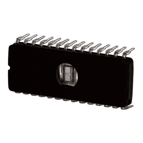
Location of the PM7600 EPROM The PM7600B EPROM is located beneath the plastic cover of the W7600 Control Module. Installation requires that the cover be removed to expose the internal circuit board. To remove the entire cover of the W7600 to expose... - Page 37 PM7600B INSTALLATION tion notch on the EPROM socket. Be sure no pins are bent under the EPROM. Fig. 7—Inspect EPROM socket before EPROM insertion. CAUTION PUSH BACK SPRING EPROMs will be damaged if power is applied with WITH SMALL EPROMs installed upside down. The EPROM...
-
Page 38: Programming
This run screen is determined by the ANALOG INPUTS PM7600B program that is installed in the W7600. At this Like digital inputs, analog inputs are chosen and defined point, it is possible to begin the monitoring and program- in hardware. - Page 39 PM7600B PROGRAMMING run mode. Pressing BYPASS enters the bypass mode and while analog outputs can be forced to any desired position. allows the user to override the state of any output after Also, the second level allows the user to change program entering the access code (if non-zero).
- Page 40 PM7600B PROGRAMMING date is unprogrammed.) The default position of the cursor SCH# 03 UNOCC UNOCC is on the month of the start date field. Using NEXT (∨) or more 07:00A 09:00A 12:00P 04:00P PREVIOUS (∧), scroll through the special schedules al- ready programmed.
- Page 41 PM7600B PROGRAMMING ASSIGNING EVENT SCHEDULES TO TIME-OF- ON RUN SCREEN display appears. Press NEXT and DAY SCHEDULES the SET CLOCK display appears. Select the TOD main menu screen and then the EQUIP- MENT screen using the tab keys. The default position of...
- Page 42 PM7600B PROGRAMMING REVIEWING W7600 PROGRAM DIGITAL OUTPUT STATUS INTERPRETATION To review W7600 program information, press the RE- • This display shows the digital output point as either VIEW key. With the cursor under PROGRAM, press the being ON or OFF.
- Page 43 PM7600B PROGRAMMING REVIEWING UNACKNOWLEDGED ALARMS ENTER ACCESS CODE After pressing REVIEW, the default position of the more 0 0 0 0 cursor is under the PROGRAM selection. To review the unacknowledged alarms, use LEFT/RIGHT TAB (</>) to To initiate a bypass, move the cursor under the digital or...
- Page 44 PM7600B PROGRAMMING NOTES 63-4309—2...
- Page 45 PM7600B PROGRAMMING PM7600B RUN SCREEN First, select the main function to be performed (PROGRAM, 4 keys for SELECTING main functions PM7600B PROGRAMMING SUMMARY REVIEW, BYPASS, or RUN) by pressing the desired key. To PROGRAM REVIEW BYPASS Run Screen (Normal Operation)
- Page 46 PM7600B PROGRAMMING REVIEW PM7600B REVIEW MENU (PRESS REVIEW KEY) REVIEW: PROGRAM STATUS OPERATION * ACKD ALARMS UNACKD ALARMS SYSTEM ECONOMIZER ENABLED more ACTUAL SETPOINTS: COOL HEAT SERVICE MESSAGE: SERVICE MESSAGE more +78.62 +65.50 FAN MOTOR FAILURE Q7600 OFF LINE AIRFLOW:...
- Page 47 PM7600B PROGRAMMING BYPASS PM7600B BYPASS FUNCTION (PRESS BYPASS KEY) IF ACCESS CODE IS IF ACCESS CODE IS 0 0 0 0 NOT 0 0 0 0 ENTER NEW ACCESS CODE more 0 0 0 0 ENTER ACCESS CODE more 0 0 0 0...
-
Page 48: Checkout
PM7600B CHECKOUT • TROUBLESHOOTING/ALARMS Checkout INITIAL CHECKOUT IMPORTANT: Before applying power to the W7600 Con- Apply power after the W7600 has been configured to trol Module, the W7600 analog and digital inputs and outputs may have to be configured using the procedure accept the inputs and control the outputs of the W7600/ outlined in the Programming section. - Page 49 PM7600B TROUBLESHOOTING/ALARMS TROUBLESHOOTING BACKGROUND Fan Motor Failure While the W7600 is in the run mode, internal circuitry is Compressor 1: Failed to Pump Out checked constantly. A failure causes a specific device Compressor 2: Failed to Pump Out failure alarm to be set. The user can configure the alarm...
- Page 50 PM7600B TROUBLESHOOTING/ALARMS Failure RAM (Read and Write Failure A/D calibration failure. Memory) failure. Symptoms • W7600A-F Control Module Symptoms W7600A-F Control Module LED LED is blinking at a rate of 25 on on for one second and off for a blip and off blinks per 10 second pe- (one-tenth of a second).
- Page 51 PM7600B TROUBLESHOOTING/ALARMS Failure W7601A,B required and not Failure A/D 50/60 Hz line failure. present. Symptoms • W7600A-F Control Module Symptoms W7600A-F Control Module LED LED is blinking at a rate of 25 on blinks on and off 25 times in 10 and off blinks per 10 second pe- seconds.
- Page 52 PM7600B TROUBLESHOOTING/ALARMS Failure Bad 50/60 Hz line. Failure Q7600 off-line. Symptoms W7600A-F LED is blinking at a Symptoms • W7600A-F LED blinks at 25 rate of 25 on and off blinks per 10 cycles in 10 seconds. second period. Q7600 Down-No •...
- Page 53 PM7600B TROUBLESHOOTING/ALARMS TROUBLESHOOTING MINOR DEVICE FAILURES PARAMETER files contain information about the char- Minor Device Failures result in the partial, temporary, acteristics of control. These files include clock information, occasionally permanent disability of the W7600A-F algo- set points and control information, time schedule informa- rithms.
- Page 54 PM7600B TROUBLESHOOTING/ALARMS Failure AO (Analog Output) configu- Failure RD (Remote Digital) configu- ration file lost. ration file lost. Symptoms Remote Digital Config Has Been Symptoms Analog Output Config Has Been Lost displayed on the S7600A. Lost on the S7600A display.
- Page 55 PM7600B TROUBLESHOOTING/ALARMS Failure Day Schedules assignments lost Failure Control number configuration file lost. Symptons Day Schedules Assignments Lost displayed on S7600A. Symptoms Control Number Config Has Been Lost displayed on the S7600A. Cause Checksum error in parameter da- tabase. Cause Checksum error in control num- ber configuration database.
- Page 56 Alarm Priority Configu- ration. Home and Building Control Home and Building Control Helping You Control Your World Honeywell Inc. Honeywell Limited—Honeywell Limitée 1985 Douglas Drive North 740 Ellesmere Road Golden Valley, Minnesota 55422 Scarborough, Ontario M1P 2V9 QUALITY IS KEY 63-4309—2...