Table of Contents
Advertisement
Advertisement
Table of Contents

Related Manuals for Unimig VIPER 182 Mk II


Summary of Contents for Unimig VIPER 182 Mk II
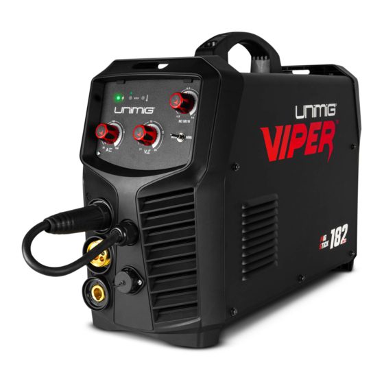
- Page 1 VIPER 182 Mk II U14001K | Operating Manual...
-
Page 3: Table Of Contents
CONTENTS SAFETY TECHNICAL DATA MACHINE LAYOUT WHAT’S IN THE BOX SETUP FOR MIG (GASLESS) SETUP FOR MIG (GAS-SHIELDED) MIG WELDING GUIDE SETUP FOR SPOOL GUN CHANGING THE MIG TORCH LINER CHANGING THE MIG TORCH LINER (ALUMINIUM) SETUP FOR STICK (MMA) WELDING MMA (STICK) WELDING GUIDE TORCH BREAKDOWN &... -
Page 4: Safety
SAFETY Welding and cutting equipment can be dangerous to both the operator and people in or near the surrounding working area if the equipment is not correctly operated. Equipment must only be used under the strict and comprehensive observance of all relevant safety regulations. Read and understand this instruction manual carefully before the installation and operation of this equipment. - Page 5 SAFETY Fire hazard. Welding/cutting on closed containers, such as tanks, drums, or pipes, can cause them to explode. Flying sparks from the welding/cutting arc, hot workpiece, and hot equipment can cause fires and burns. Accidental contact of the electrode to metal objects can cause sparks, explosion, overheating, or fire. Check and be sure the area is safe before doing any welding/cutting.
- Page 6 SAFETY CAUTION 1. Working Environment. The environment in which this welding/cutting equipment is installed must be free of grinding dust, corrosive chemicals, flammable gas or materials etc., and at no more than a maximum of 80% humidity. ii. When using the machine outdoors, protect the machine from direct sunlight, rainwater and snow, etc.; the temperature of the working environment should be maintained within -10°C to +40°C.
- Page 7 SAFETY ATTENTION! - CHECK FOR GAS LEAKAGE At initial set up and at regular intervals we recommend to check for gas leakage Recommended procedure is as follows: 1. Connect the regulator and gas hose assembly and tighten all connectors and clamps. 2.
-
Page 8: Technical Data
TECHNICAL DATA VIPER™ 182 Mk II MIG/STICK Welder Key Features: • Spool Gun Ready • Geared Wire Drive • 10 AMP Plug TECHNICAL DATA STICK SPECIFICATIONS SKU U11002K STICK WELDING CURRENT RANGE 10-160A PRIMARY INPUT VOLTAGE 240V Single Phase STICK DUTY CYCLE @ 40°C 10% @ 160A SUPPLY PLUG 10 AMP STICK ELECTRODE RANGE 2.5-4.0mm RATED INPUT POWER (kVA) 7.1... -
Page 9: Machine Layout
MACHINE LAYOUT Front Panel Layout 1. “+” Output terminal 2. Euro connection 3. “-” Output terminal 4. Amperage control knob in MMA 5. Thermal Overload LED 6. Power LED 7. VRD LED 8. MIG/MMA switch 9. Wire feed speed control in MIG 10. - Page 10 MACHINE LAYOUT STANDARD SPOOL GUN Burnback Adjustment Interior Layout 19. Wire feeding spool holder 20. Burn-back control knob 21. Manual wire feeding button 22. Spool Gun selecting switch 23. Wire feeder...
-
Page 11: What's In The Box
WHAT’S IN THE BOX Includes: • 1 x 0.8mm Contact Tip • 1 x Tip Holder • 1 x Gas Nozzle VIPER 182 Mk II MIG/STICK Welder 3m SB15 MIG Torch 3m Electrode Holder Includes: • 1 x 0.8-0.9mm “V GROOVE” 30/22 •... -
Page 12: Setup For Mig (Gasless)
SETUP FOR MIG (GASLESS) Connect the polarity cable to the negative (-) Connect the earth clamp to the positive (+) dinse connection, twist to lock in place. dinse connection, twist to lock in place. Connect the MIG torch to the Euro connection, Connect the plug into a 10 AMP socket, then and twist end to secure in place. - Page 13 SETUP FOR MIG (GASLESS) Select MIG on the MIG/MMA selector. Select Standard on the Standard/Spool Gun selector. STANDARD SPOOL GUN Burnback Adjustment Pull down the roller tension knob to release Unscrew the roller cap. the wire drive.
- Page 14 SETUP FOR MIG (GASLESS) Ensure you have an Knurled (F Groove) drive Unscrew spool retaining nut. roller installed. If not, fit correct roller and replace the roller cover. Burnback Adjustment Place 5kg wire spool onto the spool holder. For Tighten spool retaining nut. 1kg spool, see step 18.
- Page 15 SETUP FOR MIG (GASLESS) Feed wire through the inlet guide tube through Lift roller tension knob to lock wire in place. to the outlet guide tube. Ensure that the wire Twist to tighten. passes through the roller. Burnback Adjustment Remove front end consumables from the MIG Hold the Wire Inch button to feed wire through torch.
- Page 16 SETUP FOR MIG (GASLESS) Replace front end consumables on the MIG Adjust voltage and wire speed according to torch. your material and thickness. Adjust the burn back control to prevent the Connect earth clamp to your workpiece. wire sticking in the weld pool. Burn back control is located above the wire feed motor.
- Page 17 SETUP FOR MIG (GASLESS) Line up the torch with your workpiece, then For 1kg spool: After removing spool holder simply pull the trigger to initiate the weld. For nut, unscrew the 1kg spool bolt located inside gasless MIG, the drag method is recommended the spool holder housing.
-
Page 18: Setup For Mig (Gas-Shielded)
SETUP FOR MIG (GAS-SHIELDED) Connect the polarity cable to the positive (+) Connect the earth clamp to the negative (-) dinse connection, twist to lock in place. dinse connection, twist to lock in place. Connect the MIG torch to the Euro connection, Connect the plug into a 10 AMP socket, then and twist end to secure in place. - Page 19 SETUP FOR MIG (GAS-SHIELDED) Select MIG on the MIG/MMA selector. Select Standard on the Standard/Spool Gun selector. STANDARD SPOOL GUN Burnback Adjustment Pull down the roller tension knob to release Unscrew the roller cap. the wire drive.
- Page 20 SETUP FOR MIG (GAS-SHIELDED) Ensure you have an V Groove drive roller Unscrew spool retaining nut. installed. If not, fit correct roller and replace the roller cover. Burnback Adjustment Place 5kg wire spool onto the spool holder. For Tighten spool retaining nut. 1kg spool, see step 27.
- Page 21 SETUP FOR MIG (GAS-SHIELDED) Feed wire through the inlet guide tube through Lift roller tension knob to lock wire in place. to the outlet guide tube. Ensure that the wire Twist to tighten. passes through the roller. Burnback Adjustment Remove front end consumables from the MIG Hold the Wire Inch button to feed wire through torch.
- Page 22 SETUP FOR MIG (GAS-SHIELDED) Replace front end consumables on the MIG Place twin gauge argon regulator into your gas torch. outlet. Tighten securely with wrench. Connect gas hose the the regulator outlet, and crimp in place.
- Page 23 SETUP FOR MIG (GAS-SHIELDED) Adjust gas glow to 8-10L/min. Connect gas hose to the gas inlet on the rear of the machine. GAS IN Adjust voltage and wire speed according to Adjust the burn back control to prevent the your material and thickness. wire sticking in the weld pool.
- Page 24 SETUP FOR MIG (GAS-SHIELDED) Connect earth clamp to your workpiece. Line up the torch with your workpiece, then simply pull the trigger to initiate the weld. For gas-shielded MIG, the push method is recommended for optimum weld quality. Release trigger to end the weld. For 1kg spool: After removing spool holder For 1kg spool: Remove spool holder housing nut, unscrew the 1kg spool bolt located inside...
- Page 25 SETUP FOR MIG (GAS-SHIELDED) For 1kg spool: Place 1kg spool over 1kg spool housing, then tighten and secure with 1kg spool bolt and nut. Burnback Adjustment...
-
Page 26: Mig Welding Guide
MIG WELDING GUIDE MIG (Metal Inert Gas) Welding MIG (metal inert gas) welding also known as GMAW (gas metal arc welding) or MAG (metal active gas welding), is a semi-automatic or automatic arc welding process in which a continuous and consumable wire electrode and a shielding gas are fed through a welding gun. - Page 27 MIG WELDING GUIDE Basic MIG Welding Good weld quality and weld profile depend on gun angle, the direction of travel, electrode extension (stick out), travel speed, the thickness of base metal, wire feed speed (amperage) and arc voltage. To follow are some basic guides to assist with your setup.
- Page 28 MIG WELDING GUIDE Travel Angle Travel angle is the right to left, relative to the direction of welding. A travel angle of 5°- 15° is ideal and produces the right level of control over the weld pool. A travel angle higher than 20° will give an unstable arc condition with poor weld metal transfer, less penetration, high levels of spatter, weak gas shield and poor quality finished weld.
- Page 29 MIG WELDING GUIDE Travel Speed Travel speed is the rate that the gun is moved along the weld joint and is usually measured in mm per minute. Travel speeds can vary depending on conditions and the welder's skill and is limited to the welder's ability to control the weld pool.
- Page 30 MIG WELDING GUIDE Wire types and sizes Use the correct wire type for the base metal being welded. Use stainless steel wire for stainless steel, aluminium wires for aluminium and steel wires for steel. Use a smaller diameter wire for thin base metals. For thicker materials use a larger wire diameter and larger machine, check the recommended welding capability of your machine.
-
Page 31: Setup For Spool Gun
SETUP FOR SPOOL GUN Connect the polarity cable to the positive (+) Connect the earth clamp to the negative (-) dinse connection, twist to lock in place. dinse connection, twist to lock in place. Connect the Spool Gun to the Euro connection, Connect the plug into a 10 AMP socket, then and twist end to secure in place. - Page 32 SETUP FOR SPOOL GUN Select MIG on the MIG/MMA selector. Select Spool Gun on the Standard/Spool Gun selector. STANDARD SPOOL GUN Burnback Adjustment Unscrew spool holder. Push back the spool guides, and place wire spool onto the spool nut.
- Page 33 SETUP FOR SPOOL GUN Feed wire through the inlet guide tube. Open cover, and loosen roller lock. Open the wire drive. Unscrew roller nut.
- Page 34 SETUP FOR SPOOL GUN Ensure you have the correct roller for the wire Replace roller nut and tighten. size you are using. If not, replace with correct size. Feed wire through roller, and through the Close wire drive and tighten roller tension outlet guide tube.
- Page 35 SETUP FOR SPOOL GUN Remove front end consumables. Push trigger to feed wire out the torch nozzle. Replace front end consumables. Replace spool cover and tighten.
- Page 36 SETUP FOR SPOOL GUN Place twin gauge argon regulator into your gas Tighten securely with wrench. outlet. Connect gas hose the the regulator outlet, and Adjust gas glow to 8-10L/min. crimp in place.
- Page 37 SETUP FOR SPOOL GUN Connect gas hose to the gas inlet on the rear Adjust voltage and wire speed according to of the machine. your material and thickness. GAS IN Adjust the burn back control to prevent the Connect earth clamp to your workpiece. wire sticking in the weld pool.
- Page 38 SETUP FOR SPOOL GUN Line up the torch with your workpiece, then simply pull the trigger to initiate the weld. Release trigger to end the weld.
-
Page 39: Changing The Mig Torch Liner
CHANGING THE MIG TORCH LINER Remove MIG torch front end parts. Remove the liner retaining nut. Carefully pull out and completely remove the Carefully feed in the new liner down the torch existing liner. Ensure MIG torch is completely lead all the way to exit the torch neck. unravelled until setup is complete. - Page 40 CHANGING THE MIG TORCH LINER Fit the liner retaining nut and screw only 1/2 Snip the excess liner off, about the length of way down. the where tip holder sits past the end of the torch neck. Replace the front end parts (9) Fully screw down the liner retaining nut and nip it up tight.
-
Page 41: Changing The Mig Torch Liner (Aluminium)
CHANGING THE MIG TORCH LINER (ALUMINIUM) Remove MIG torch front end parts. Remove the liner retaining nut. Carefully pull out and completely remove the Fit the neck spring to the front end of the existing liner. Ensure MIG torch is completely aluminium liner. - Page 42 CHANGING THE MIG TORCH LINER (ALUMINIUM) Feed liner and neck spring through the torch, Push the liner firmly into the torch lead and then fit liner collet, liner O-ring and liner tighten the liner retaining nut. retaining nut. Loosen the inlet guide tube retaining screw. Remove the inlet guide tube using long nose pliers.
- Page 43 CHANGING THE MIG TORCH LINER (ALUMINIUM) Install a U groove drive roller of the correct size Feed liner through euro connection, and for the diameter wire being used. connect and tighten the torch. Take the extended polymide liner all the way Cut the extended Polymide liner with a sharp up and over the drive roller.
- Page 44 CHANGING THE MIG TORCH LINER (ALUMINIUM) Replace the front end parts.
-
Page 45: Setup For Stick (Mma) Welding
SETUP FOR STICK (MMA) WELDING For DC+ electrodes, connect earth clamp to the For DC- electrodes, connect earth clamp to the negative (-) dinse connection, and electrode positive (+) dinse connection, and electrode holder to the positive (+) dinse connection. holder to the negative (-) dinse connection. - Page 46 SETUP FOR STICK (MMA) WELDING Twist electrode holder to loosen grip. Place electrode into electrode holder. Twist electrode holder to tighten and securely Adjust amperage to desired setting. grip electrode.
- Page 47 SETUP FOR STICK (MMA) WELDING Connect earth clamp to your workpiece. Strike electrode against workpiece to initiate arc. Drag along workpiece to weld. Pull the electrode away from the workpiece to finish weld.
-
Page 48: Mma (Stick) Welding Guide
MMA (STICK) WELDING GUIDE STICK (MMA / Manual Metal Arc) Welding One of the most common types of arc welding is manual metal arc welding (MMA) or MMA welding. An electric current is used to strike an arc between the base material and a consumable electrode rod or ‘stick’. The electrode rod is made of a material that is compatible with the base material being welded and is covered with a flux that gives off gaseous vapours that serve as a shielding gas and providing a layer of slag, both of which protect the weld area from atmospheric contamination. - Page 49 MMA (STICK) WELDING GUIDE Electrode Selection As a general rule, the selection of an electrode is straight forward, in that it is only a matter of selecting an electrode of similar composition to the parent metal. However, for some metals, there is a choice of several electrodes, each of which has particular properties to suit specific classes of work.
-
Page 50: Torch Breakdown & Spares
TORCH BREAKDOWN & SPARES SB15 BINZEL Style MIG Torch Part No. Length SB15-3M SB15-4M SB15-5M TORCH SPARES TECHNICAL DATA SNK15 Swan Neck Assembly COOLING METHOD Air Cooled SNKF15 Flexible Swan Neck DUTY CYCLE - CO2 60% @ 180A UG1515 Ergo Handle Location Body DUTY CYCLE - MIXED GAS 60% @ 150A UG8015 Handle Cable Support C/W Ball Joint... - Page 51 TORCH BREAKDOWN & SPARES SB15 MIG Torch Consumables Description PCTH15 TIP HOLDER Description PGNS15 NOZZLE SPRING Description PCT0008-06 CONTACT TIPS - Steel 0.6mm PCT0008-08 CONTACT TIPS - Steel 0.8mm PCT0008-09 CONTACT TIPS - Steel 0.9mm PCT0008-10 CONTACT TIPS - Steel 1.0mm PCT0008-12 CONTACT TIPS - Steel 1.2mm PCTAL0008-09...
-
Page 52: Mig Drive Rollers
MIG DRIVE ROLLERS Drive Roller Selection The importance of smooth, consistent wire feeding during MIG welding cannot be emphasised enough. The smoother the wire feed, the better the welding will be. Feed rollers or drive rollers are used to feed the wire mechanically along the length of the welding gun. -
Page 53: Machine Parts Breakdown
MACHINE PARTS BREAKDOWN 10 11 MACHINE SPARES MACHINE SPARES 10050074 Handle 10068307 Base Board Side Penal 10070464 Vrd Board 10016524 Door Holder 10062441 Rocker Switch Basecover 10054623 Inverter 10052166 Loose-Leaf 10070471 Main Board 10068849 Rear Panel 10054164 Long Column 10001381 Solenoid Valve 10054163 Short Column... -
Page 54: Faq & Troubleshooting
FAQ & TROUBLESHOOTING WARNING: There are extremely dangerous voltage and power levels present inside this unit. Do not attempt to diagnose or repair unit by removing external cover unless you are an authorised repair agent for UNIMIG. MIG TROUBLESHOOTING 1. Excessive Spatter. - Page 55 FAQ & TROUBLESHOOTING 6. Lack of penetration: Shallow fusion between weld metal and base metal • Poor incorrect joint preparation. Material too thick. Joint preparation and design needs to allow access to bottom of groove while maintaining proper welding wire extension and arc characteristics. Keep the arc at the leading edge of the weld pool and maintain the gun angle at 5 &...
- Page 56 FAQ & TROUBLESHOOTING STICK (MMA) TROUBLESHOOTING 1. No arc. • Incomplete welding circuit. Check earth lead is connected. Check all cable connections. . • Wrong mode selected. Check the MMA selector switch is selected. • No power supply. Check that the machine is switched on and has a power supply. 2.
- Page 57 NOTES...
- Page 58 NOTES...
- Page 59 NOTES...
- Page 60 PH: (02) 9780 4200 PH: (07) 3333 2855 PH: (03) 8682 9911 PH: (08) 6363 5111 FAX: (02) 9780 4210 FAX: (07) 3274 5829 FAX: (03) 9333 7867 FAX: (08) 9417 4781 EMAIL: sales@unimig.com.au EMAIL: qld@unimig.com.au EMAIL: vicsales@unimig.com.au EMAIL: wasales@unimig.com.au...