Table of Contents
Advertisement
Quick Links
Cisco ASR 901 10G Series Aggregation
Services Router Hardware Installation
Guide
November, 2014
Cisco Systems, Inc.
www.cisco.com
Cisco has more than 200 offices worldwide.
Addresses, phone numbers, and fax numbers
are listed on the Cisco website at
www.cisco.com/go/offices.
Text Part Number: OL-28105-02
Advertisement
Table of Contents
Troubleshooting

Related Manuals for Cisco ASR 901 10G Series


Summary of Contents for Cisco ASR 901 10G Series
- Page 1 Cisco ASR 901 10G Series Aggregation Services Router Hardware Installation Guide November, 2014 Cisco Systems, Inc. www.cisco.com Cisco has more than 200 offices worldwide. Addresses, phone numbers, and fax numbers are listed on the Cisco website at www.cisco.com/go/offices. Text Part Number: OL-28105-02...
- Page 2 REPRESENTATIVE FOR A COPY. Cisco and the Cisco logo are trademarks or registered trademarks of Cisco and/or its affiliates in the U.S. and other countries. To view a list of Cisco trademarks, go to this URL: www.cisco.com/go/trademarks. Third-party trademarks mentioned are the property of their respective owners. The use of the word partner does not imply a partnership relationship between Cisco and any other company.
-
Page 3: Table Of Contents
Preparing to Install the Router C H A P T E R Safety Guidelines Safety with Equipment Safety with Electricity Preventing Electrostatic Discharge Damage Prerequisites Site Planning Power Supply Considerations Cisco ASR 901 10G Series Aggregation Services Router Hardware Installation Guide OL-28105-02... - Page 4 3-21 Connecting T1 and E1 Interface Cables 3-21 Connecting SFP Cables 3-22 Connecting Cables to the BITS Interface 3-22 Connecting GPS Cables 3-22 Connecting to Alarm Port 3-23 Cisco ASR 901 10G Series Aggregation Services Router Hardware Installation Guide OL-28105-02...
- Page 5 SFP and SFP+ Port Pinouts and Cable Specifications T1/E1 Port Pinouts Console Port Signals and Pinouts Console Port Signals and Pinouts Identifying a Rollover Cable BITS Port Pinouts Time of Day Pinouts GPS Port Pinouts Cisco ASR 901 10G Series Aggregation Services Router Hardware Installation Guide OL-28105-02...
- Page 6 Contents Alarm Port Pinouts Management Ethernet Port Pinouts Site Log A P P E N D I X N D E X Cisco ASR 901 10G Series Aggregation Services Router Hardware Installation Guide OL-28105-02...
-
Page 7: About This Guide
Not all Cisco documents use a Document Revision History table. Revision Date Change Summary OL-28105-01 October 2012 Initial version of the document. OL-28105-02 March 2014 Added information on new variants of the router. Cisco ASR 901 10G Series Aggregation Services Router Hardware Installation Guide OL-28105-02... -
Page 8: Objectives
Cisco IOS configuration guide and command reference publications. For more information, see “Obtaining Documentation, Obtaining Support, and Security Guidelines” section on page Warranty, service, and support information is in the Cisco Information Packet that is shipped with your router. -
Page 9: Safety Warnings
SAVE THESE INSTRUCTIONS Related Documentation For additional information, refer to the following documents: • Cisco Regulatory Compliance and Safety Information for Cisco ASR 901 Series Aggregation Services Router Cisco ASR 901 Series Aggregation Services Router Software Configuration Guide • •... -
Page 10: Obtaining Documentation, Obtaining Support, And Security Guidelines
For information on obtaining documentation, obtaining support, providing documentation feedback, security guidelines, and also recommended aliases and general Cisco documents, see the monthly What’s New in Cisco Product Documentation, which also lists all new and revised Cisco technical documentation, at: http://www.cisco.com/en/US/docs/general/whatsnew/whatsnew.html... -
Page 11: Chapter 1 Introduction
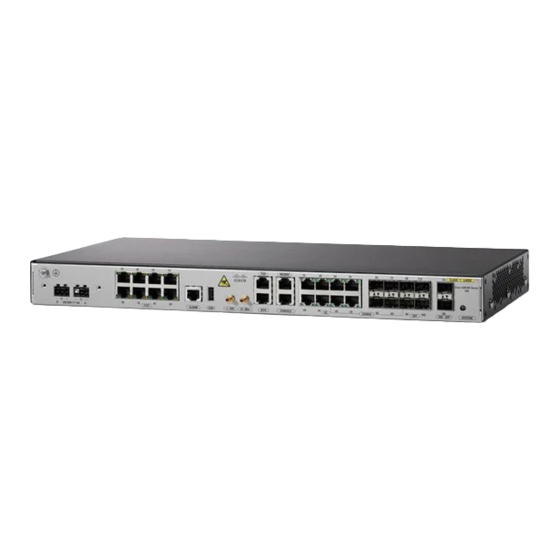
C H A P T E R Introduction The Cisco ASR 901 10G router is a cell site gateway platform specifically designed to provide transport for both legacy TDM and Ethernet traffic over a single converged network. The Cisco ASR 901 10G router is used at the cell site as a part of a 2G, 3G, or 4G radio access network (RAN) traffic. -
Page 12: Cisco Asr 901 10G Router-Front View Of Tdm Version
Cisco ASR 901 10G Router—Front View of TDM Version The front panel of the Cisco ASR 901 10G (TDM version) router has the following components: Eight T1/E1 ports, labelled T1/E1 (positions 0, 1, 2, 3, 4, 5, 6, and 7) •... -
Page 13: Cisco Asr 901 10G Router-Front View Of Ethernet Version
– Chassis: Single LED for multiple conditions – Figure 1-1 shows the front view of the Cisco ASR 901 10G router (TDM version) with each interface module. Figure 1-1 Cisco ASR 901 10G Router—Front View of TDM Version Power LED... -
Page 14: Cisco Asr 901 10G Router-Rear View
SFP ports – Chassis: Single LED for multiple conditions – Figure 1-2 shows the front view of the Cisco ASR 901 10G router (Ethernet version) with each interface module. Figure 1-2 Cisco ASR 901 Router—Front View of Ethernet Version Power LED... -
Page 15: Leds
A-4. Power Supply The Cisco ASR 901 10G router is equipped with an internal -24/-60 Volts Direct Current (VDC). The router is provided with a single AC power supply or DC (1+1 Redundant) power supply. The power input connectors are located at the front left-side side of the router. The DC power connector has the standard A and B feeds for DC redundancy. - Page 16 The addition of Primary Protectors is not sufficient protection in order to connect these interfaces metallically to OSP wiring. Table 1-1 lists the DC power supply specifications for the Cisco ASR 901 10G router. Table 1-1 Cisco ASR 901 10G Router DC Power Supply Specifications...
- Page 17 1A at 100 VAC and 60 Hz. The Cisco ASR 901 10G router uses two 3-pin connectors (part number 27-1892-01) for DC input to the power supply. The terminal block is part of the accessory kit (part number 53-3438-01), which ships with the Cisco ASR 901 10G router.
-
Page 18: Environmental Monitoring Temperature Sensor
Chassis Ground Environmental Monitoring Temperature Sensor The Cisco ASR 901 10G router has a temperature sensor to detect overtemperature conditions inside the chassis. The overtemperature detection trips at 70°C. This condition is reported to the processor as an interrupt, where the software generates the appropriate alarms. If the router reaches a temperature of 90°C, the power supply cycles itself to prevent the router from exceeding the maximum temperature... -
Page 19: System Specifications
61 dBA with 19 cfm fan Air Flow Left to right, 57 cfm Router Interface Numbering The following section explains router interface numbering and interface labels for the Cisco ASR 901 10G router. Cisco ASR 901 10G Series Aggregation Services Router Hardware Installation Guide OL-28105-02... -
Page 20: Cisco Asr 901 10G Router
Introduction Router Interface Numbering Cisco ASR 901 10G Router Each network interface on a Cisco ASR 901 10G 10G router is identified by a slot number and a port number, explained in this sequence: • Logical slot numbers starts from 0 for all built-in interfaces. The numbering format is... -
Page 21: Regulatory Compliance
Power connector Onboard Power Connector Regulatory Compliance For regulatory compliance and safety information, see Cisco Regulatory Compliance and Safety Information for Cisco ASR 901 Series Aggregation Services Router. Cisco ASR 901 10G Series Aggregation Services Router Hardware Installation Guide 1-11 OL-28105-02... - Page 22 Chapter 1 Introduction Regulatory Compliance Cisco ASR 901 10G Series Aggregation Services Router Hardware Installation Guide 1-12 OL-28105-02...
-
Page 23: Chapter 2 Preparing To Install The Router
C H A P T E R Preparing to Install the Router This chapter describes site requirements and equipment used to install the Cisco ASR 901 10G router. It includes the following sections: Safety Guidelines, page 2-1 • Prerequisites, page 2-4 •... -
Page 24: Safety With Electricity
Before working on the system, switch off the DC main circuit breaker and disconnect the power • terminal block cable. Disconnect all power before performing the following: • Cisco ASR 901 10G Series Aggregation Services Router Hardware Installation Guide OL-28105-02... -
Page 25: Preventing Electrostatic Discharge Damage
If no wrist strap is available, ground yourself by touching a metal part of the chassis. For the safety of your equipment, periodically check the resistance value of the antistatic wrist strap. It Caution should be between 1 and 10 Mohm. Cisco ASR 901 10G Series Aggregation Services Router Hardware Installation Guide OL-28105-02... -
Page 26: Prerequisites
Ideally, you should have prepared the installation site beforehand. As part of your preparation, obtain a floor plan of the site and the equipment rack where the Cisco ASR 901 10G router would be housed. Determine the location of any existing routers and their interconnections, including communications and power. -
Page 27: Air Flow Guidelines
Use the following guidelines to plan your equipment rack configuration: Mount the Cisco ASR 901 10G router in a 19-inch rack (with a 17.5- or 17.75-inch opening). • Beside air flow, you must allow clearance around the rack for maintenance. -
Page 28: Unpacking And Checking The Contents Of Your Shipment
Unpacking and Checking the Contents of your Shipment The shipping package for the Cisco ASR 901 10G router is designed to reduce the possibility of product damage associated with routine handling experienced during shipment. Do not remove the router from its shipping container until you are ready to install it. -
Page 29: Installation Checklist
Installation Checklist for Site: Router Name: Task Verified by Date Installation checklist copied Background information placed in site log Site power voltages verified Installation site power check completed Required tools available Cisco ASR 901 10G Series Aggregation Services Router Hardware Installation Guide OL-28105-02... -
Page 30: Creating A Site Log
The console port provides access to the router either locally (using a console terminal), or remotely (using a modem). Console and rollover cables are not included with the Cisco ASR 901 10G router. You can order the Note console cable from Cisco Systems, Inc. - Page 31 For cable and port pinouts, see the online document Cisco Modular Access Router Cable Specifications. This document is provided on the documentation DVD that accompanied your router (if ordered). Cisco ASR 901 10G Series Aggregation Services Router Hardware Installation Guide OL-28105-02...
- Page 32 Chapter 2 Preparing to Install the Router Console Port Considerations Cisco ASR 901 10G Series Aggregation Services Router Hardware Installation Guide 2-10 OL-28105-02...
-
Page 33: Chapter 3 Installing The Cisco Asr 901 10G Router
C H A P T E R Installing the Cisco ASR 901 10G Router This chapter describes how to install the Cisco ASR 901 10G router, and how to connect it to external devices. These are the following sections: Network Modules, page 3-1 •... -
Page 34: Mounting The Cisco Asr 901 10G Router
Each Cisco ASR 901 10G router includes rack-mounting brackets. Using the rack-mounting brackets, you can mount the Cisco ASR 901 10G router in a 19-inch, 23-inch, or an ETSI rack that conforms to the EIA-310-D specification. -
Page 35: Attaching Brackets To The Router
Mounting the Cisco ASR 901 10G Router Attaching Brackets to the Router, page 3-3 • Mounting the Cisco ASR 901 10G Router in a Rack, page 3-7 • Attaching Brackets to the Router The bracket orientation and the brackets that you use depend on whether you are attaching the brackets for a 19-inch, 23-inch, or an ETSI rack. - Page 36 Figure 3-2 shows how to attach brackets for 19-inch racks on the router. Figure 3-2 Attaching Brackets for 19-Inch Racks Phillips flat-head screws Front-mounting position Mid-mounting position Rear-mounting position Cisco ASR 901 10G Series Aggregation Services Router Hardware Installation Guide OL-28105-02...
- Page 37 Figure 3-3 shows how to attach brackets for 23-inch racks on the router. Figure 3-3 Attaching Brackets for 23-Inch Racks Phillips flat-head screws Front-mounting position Mid-mounting position Rear-mounting position Cisco ASR 901 10G Series Aggregation Services Router Hardware Installation Guide OL-28105-02...
- Page 38 Figure 3-4 shows how to attach brackets for ETSI racks on the router. Figure 3-4 Attaching Brackets for ETSI Racks Phillips flat-head screws Front-mounting position Mid-mounting position Rear-mounting position Cisco ASR 901 10G Series Aggregation Services Router Hardware Installation Guide OL-28105-02...
-
Page 39: Mounting The Cisco Asr 901 10G Router In A Rack
Mounting the Cisco ASR 901 10G Router in a Rack Perform the steps given below to mount the router into the equipment rack. To secure the Cisco ASR 901 10G router to the equipment rack, you must use the two mounting screws Note (provided) for each side or follow your local practices for installing the router into your equipment rack. -
Page 40: Attaching Brackets For Wall-Mounting
The router can be wall mounted with the ports either facing up or down. The illustration used in the procedure below uses the orientation of ports facing upwards. Cisco ASR 901 10G Series Aggregation Services Router Hardware Installation Guide OL-28105-02... -
Page 41: Mounting The Router On A Wall
Number 6-32 x 0.25-inch mounting screws (two on each side). Tighten the screws using a 1/4-inch flat-blade screwdriver (each side). Step 4 Figure 3-6 Mounting the Router on a Wall User-supplied screws — Cisco ASR 901 10G Series Aggregation Services Router Hardware Installation Guide OL-28105-02... -
Page 42: Connecting The Chassis Ground And Power
Grounding the Cisco ASR 901 10G Router The Cisco ASR 901 10G router provides a grounding point on the rear of the unit for a 2-hole lug. To ensure the chassis ground connection that you provide is adequate, you need the following parts and... - Page 43 This unit is to be installed in a restrictive access location and must be permanently grounded to minimum 6-AWG copper ground wire. Perform the steps given below to ground the Cisco ASR 901 10G router using a 2-hole lug and the corresponding mounting point. Most carriers require a 6-AWG ground connection. Verify your carrier’s requirements for the ground connection.
-
Page 44: Power Connection Compliance
10 A minimum, 60 VDC. Statement 1005 Complete the following steps to connect the DC power supply to the Cisco ASR 901 10G router: Cisco ASR 901 10G Series Aggregation Services Router Hardware Installation Guide... -
Page 45: Installing The Dc Power Cord Retainer
The DC-input wire should go through the cable holder before the screw is fastened. Complete the following steps to install the cable holders to the Cisco ASR 901 10G router. Cisco ASR 901 10G Series Aggregation Services Router Hardware Installation Guide... - Page 46 Use a Phillips head screwdriver to attach the cable holders to the front of the router with the two screws Step 4 from the accessory kit. See Figure 3-12. Figure 3-12 Attaching Cable Holder to the Router Cable holder DC power cord DC terminal — Cisco ASR 901 10G Series Aggregation Services Router Hardware Installation Guide 3-14 OL-28105-02...
-
Page 47: Installing The Ac Power Cord Retainer
Mounting the Cisco ASR 901 10G Router Installing the AC Power Cord Retainer Complete the following steps to install the AC power cord retainer to the Cisco ASR 901 10G router using the corresponding mounting point. Choose the sleeve size of the power cord retainer based on the thickness of the cord. The smaller sleeve Step 1 can be snapped off and used for thin cords. - Page 48 Detach the sleeve, and slide it over the power cord. See Figure 3-16. Figure 3-16 Sleeve Around the Power Cord Sleeve for thin power cords AC power cord Cisco ASR 901 10G Series Aggregation Services Router Hardware Installation Guide 3-16 OL-28105-02...
-
Page 49: Installing And Removing Sfp Modules
SFP module slots on the front of the Cisco ASR 901 10G router. These field-replaceable modules provide interfaces. For a list of supported SFP modules, see the Release Notes for Cisco ASR 901 Series Aggregation Services Router. Each port must match the wavelength specifications on the other end of the cable. For reliable communications, the cable must not exceed 328 feet (100 meters). - Page 50 For fiber-optic SFP modules, insert the line card or MT-RJ cable connector into the SFP module. • For copper 1000BASE-T SFP modules, insert the RJ-45 cable connector into the SFP module. • Cisco ASR 901 10G Series Aggregation Services Router Hardware Installation Guide 3-18 OL-28105-02...
-
Page 51: Removing Sfp Modules
For fiber-optic SFP modules, insert a dust plug into the optical ports of the SFP module to keep the Step 5 optical interfaces clean. Place the removed SFP module in an antistatic bag or any other protective casing. Step 6 Cisco ASR 901 10G Series Aggregation Services Router Hardware Installation Guide 3-19 OL-28105-02... -
Page 52: Connecting Cables
The Cisco ASR 901 10G router uses RJ-45 ports for console port function. We provide the following cables and adapters for connecting the Cisco ASR 901 10G router to a console terminal: One console adapter cable (RJ-45-to-DB-9, blue) •... -
Page 53: Connecting The Network Cables
Connecting Gigabit Ethernet Interface Cables The RJ-45 port supports standard straight-through and crossover Category 5 unshielded twisted-pair (UTP) cables. Cisco Systems does not supply Category 5 UTP cables; these cables are available commercially. Complete the following steps to connect the cable to the router Gigabit Ethernet port: Ensure the router is powered off. -
Page 54: Connecting Sfp Cables
B-6. Connecting GPS Cables The following sections describe how to connect cables from the Cisco ASR 901 10G router to a GPS unit for input or output timing or frequency. Connecting Cables to the 10Mhz or 1PPS Interface •... -
Page 55: Connecting To Alarm Port
Step 1 Connect one end of a mini-coax cable to the GPS unit. Step 2 Connect the other end of the mini-coax cable to the 10Mhz or 1PPS port on the Cisco ASR 901 10G Step 3 router. For instructions on how to configure clocking, see the Cisco ASR 901 Series Aggregation Services Router Software Configuration Guide. -
Page 56: Powering On The Router
The LED (labeled POWER) on the front panel should go ON and the fans should begin to operate. Depending on your installation, other front-panel LEDs can also come on. When the Cisco ASR 901 10G router (DC unit) is powered ON, it takes about 30 seconds for the system Note LED to turn ON. -
Page 57: Formatting Procedures For Flash Memory
Address or name of remote host []? 10.64.71.240 Source filename []? /ngmwr-advipservicesk9-mz Destination filename [ngmwr-advipservicesk9-mz]? Accessing tftp://10.64.71.240//ngmwr-advipservicesk9-mz... Erase flash: before copying? [confirm]n Loading /ngmwr-advipservicesk9-mz from 10.64.71.240 (via FastEthernet0/0): !!!!!!!!!!!!!!!!!!!!!!!!!!!!!!!!!!!!!!!!!!!!!!!!!!!!!!!!!!!!!!!!!!!!!!!!!!!!!!!!!!!!!!!!!! !!!!!!!!!!!!!!!!!!!!!!!!!!!!!! [OK - 30480936 bytes] Cisco ASR 901 10G Series Aggregation Services Router Hardware Installation Guide 3-25 OL-28105-02... -
Page 58: Displaying Contents Of The Flash Memory
To release the memory space occupied by a deleted file, enter the squeeze flash: command The following is sample output for deleting a Cisco IOS file from the flash memory, and releasing the memory space originally occupied by the file. -
Page 59: Displaying File Content
The following example shows output for the following actions: Entering the home directory of a flash memory card (flash:/) • Cisco ASR 901 10G Series Aggregation Services Router Hardware Installation Guide 3-27 OL-28105-02... -
Page 60: What To Do After Installing The Hardware
What to Do After Installing the Hardware After you install the router hardware, refer to the Cisco ASR 901 Series Aggregation Services Router Software Configuration Guide for the software configuration information. Cisco ASR 901 10G Series Aggregation Services Router Hardware Installation Guide... -
Page 61: Appendix
If you cannot locate the source of the problem, contact a customer service representative for information on how to proceed. For technical support information, see the Cisco Information Packet publication that shipped with your router. Before you call, have the following information ready: Chassis type and serial number •... -
Page 62: Troubleshooting The Power And Cooling Systems
85°C, the power supply will cycle to prevent the router from exceeding that temperature while being powered up state. See Table A-2 for help in interpreting environmental reporting features. Cisco ASR 901 10G Series Aggregation Services Router Hardware Installation Guide OL-28105-02... -
Page 63: Troubleshooting Cables And Connections
For warranty disconnected. information, refer to the Cisco Information Packet publication that shipped with your order or contact customer service. Cisco ASR 901 10G Series Aggregation Services Router Hardware Installation Guide OL-28105-02... -
Page 64: Reading The Leds
No power or unit not boot-up Alternating POST in progress Green/Off Solid Green System Healthy (normal operation) Solid Red System Faulty SFP LED SFP Link-Active Orange Link and Active Indicator Not Enabled Cisco ASR 901 10G Series Aggregation Services Router Hardware Installation Guide OL-28105-02... -
Page 65: T1/E1 Interface Leds
LEDs on the 10G SFP+ interface. Table A-7 10G SFP+ LEDs Color/State Description SFP+ Link/Active Orange Link and active indicator (labeled 10GSFP) Link not enabled Cisco ASR 901 10G Series Aggregation Services Router Hardware Installation Guide OL-28105-02... -
Page 66: Rj-45 Ethernet Interface Leds
Link with no activity (labeled L, left LED) Flash Green Link with activity No link detected 100/1000 RJ-45 speed Green Speed 1000 (labeled S, right LED) Yellow Speed 100 Cisco ASR 901 10G Series Aggregation Services Router Hardware Installation Guide OL-28105-02... -
Page 67: Appendix
The RJ-45 ports are capable of operating in both 100BaseT and 1000BaseT modes. Note Figure B-1 shows the RJ-45 connector and port, and Table B-1 lists the connector pinouts and signals. Cisco ASR 901 10G Series Aggregation Services Router Hardware Installation Guide OL-28105-02... -
Page 68: Sfp And Sfp+ Port Pinouts And Cable Specifications
RX D+ Not used RX D– SFP and SFP+ Port Pinouts and Cable Specifications For information about SFP and SFP+ modules supported by the Cisco ASR 901 10G router, including pinouts, see the Connector and Cable Specifications document on Cisco.com. -
Page 69: Console Port Signals And Pinouts
Not used Console Port Signals and Pinouts The Cisco ASR 901 10G router ships with a console cable kit, which contains the cable and adapters to connect a console terminal (an ASCII terminal or PC running terminal emulation software). The console... -
Page 70: Console Port Signals And Pinouts
Connecting the Console Port to a PC RJ-45-to-RJ-45 rollover cable Router RJ-45-to-DB-9 adapter (labeled TERMINAL) Table B-3 lists the Console port pinouts for the Cisco ASR 901 10G router. Table B-3 Console Port Pinouts Signal Name HP Pins Direction Description... - Page 71 B-5.) If you purchased your cable from Cisco Systems, pin 1 is white on one connector, and pin 8 is white on the other (a rollover cable connects pins 1 and 8, 2 and 7, 3 and 6, and 4 and 5).
-
Page 72: Identifying A Rollover Cable
Not connected Not connected Not connected Time of Day Pinouts Table B-6 list the pinouts for the Time of Day RJ-45 interface on the Cisco ASR 901 10G router. Table B-7 Time of Day RJ-45 Interface Pinout Signal Name Direction... -
Page 73: Gps Port Pinouts
Time of Day RS422 differential input or output GPS Port Pinouts The Cisco ASR 901 10G router has a 10Mhz and a 1PPS GPS port that allow you to configure input or output clocking with a GPS device. Table B-8 summarizes the pinouts for the 10Mhz and 1PPS interfaces. -
Page 74: Alarm Port Pinouts
Figure B-6 RJ-45 Connector Pinouts for Alarm 12345678 Table B-9 list the pinouts for the alarm port (RJ45) on the Cisco ASR 901 10G router. Table B-9 Alarm Port Pinout Signal Name Description Alarm input 1... -
Page 75: Management Ethernet Port Pinouts
Not connected Not connected Auxiliary Port Auxiliary port is not supported on the Cisco ASR 901 10G router and you should not try to configure the auxiliary port. Cisco ASR 901 10G Series Aggregation Services Router Hardware Installation Guide OL-28105-02... - Page 76 Appendix B Cable Specifications Auxiliary Port Cisco ASR 901 10G Series Aggregation Services Router Hardware Installation Guide B-10 OL-28105-02...
-
Page 77: Appendix
• Upgrade, removal, and maintenance procedures—Use the site log as a record of ongoing router maintenance and expansion history. Each time a task is performed on the Cisco ASR 901 10G router, update the site log with the following information: Removal or replacement of interface modules –... - Page 78 Appendix C Site Log Table C-1 Site Log Date Description of Action Performed or Symptom Observed Initials Cisco ASR 901 10G Series Aggregation Services Router Hardware Installation Guide OL-28105-02...
-
Page 79: I N D E X
3-10 GPS Cables, Connecting cables to 3-22 console port GPS Interfaces, connecting cables to 3-23 adapter GPS Port Pinouts connections 2-8, 3-20 grounding considerations (warning) 3-24 Cisco ASR 901 10G Series Aggregation Services Router Hardware Installation Guide IN-1 OL-28105-02... - Page 80 3-17 to 3-18 mounting SFP Modules and Cable Specifications instructions shipment unpacking and checking site configuration network cables, connecting 3-21 environment numbering interface site log, record keeping Cisco ASR 901 10G Series Aggregation Services Router Hardware Installation Guide IN-2 OL-28105-02...
- Page 81 Time of Day Interface, Connecting cables to 3-23 tools required for installation troubleshooting cables connections cooling system front panel LEDs modules power system ventilation warning short circuit 3-12 warnings safety overview 1-ix Cisco ASR 901 10G Series Aggregation Services Router Hardware Installation Guide IN-3 OL-28105-02...
- Page 82 Index Cisco ASR 901 10G Series Aggregation Services Router Hardware Installation Guide IN-4 OL-28105-02...