Advertisement
Quick Links
INSTALLATION AND
MAINTENANCE INSTRUCTIONS
IDP-Relay
Specifications
Normal Operating Voltage:
Maximum Current Draw:
Average Operating Current: 255µA
EOL Resistance:
Temperature Range:
Humidity:
Dimensions:
Accessories:
Before Installing
This information is included as a quick reference in-
stallation guide. Refer to the appropriate Silent Knight
control panel installation manual for detailed system
information. If the modules will be installed in an exist-
ing operational system, inform the operator and local au-
thority that the system will be temporarily out of service.
Disconnect power to the control panel before installing
the modules.
NOTICE: This manual should be left with the owner/
user of this equipment.
General Description
The IDP-Relay is intended for use in intelligent, two-wire
systems where the individual address of each module is
selected using the built-in rotary switches. It allows a
compatible control panel to switch discrete contacts by
code command. The relay contains two isolated sets of
Form-C contacts, which operate as a DPDT switch and
are rated in accordance with the table in the manual.
Circuit connections to the relay contacts are not super-
vised by the module. The module also has a panel con-
trolled LED indicator.
Compatibility Requirements
To ensure proper operation, this module shall be con-
nected to a compatible Silent Knight system control panel
(list available from Silent Knight).
K200-11-00
15 to 32 VDC
6.5 mA (LED on)
Not used
32˚F to 120˚F (0˚C to 49˚C)
10% to 93% non-condensing
41/2˝ H x 4˝ W x 11/4˝ D
(Mounts to a 4˝ square
by 21/8˝ deep box.)
SMB500 Electrical Box
Mounting
The IDP-Relay mounts directly to 4˝ square electrical
boxes (see Figure 2A). The box must have a mini-
mum depth of 2
1
/
˝. Surface mounted electrical boxes
8
(SMB500) are available from Silent Knight.
Wiring
NOTE: All wiring must conform to applicable local
codes, ordinances, and regulations. When using control
modules in nonpower limited applications, the CB500
Module Barrier must be used to meet UL requirements
for the separation of power-limited and nonpower-limited
terminals and wiring. The barrier must be inserted into a
1
4˝ × 4˝ × 2
/
˝ junction box, and the control module must
8
be placed into the barrier and attached to the junction box
(Figure 2A). The power-limited wiring must be placed into
the isolated quadrant of the module barrier (Figure 2B).
1. Install module wiring in accordance with the job draw-
ings and appropriate wiring diagrams.
2. Set the address on the module per job drawings.
3. Secure module to electrical box (supplied by installer),
as shown in Figure 2A.
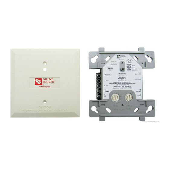
Figure 1. Controls and indicators:
LOOP
Figure 2A. Module mounting with barrier:
C0217-01
1
9
0
7 8
9
6
5
8
4
1
3
2
7
2
1 0
TENS
6 7 8 9
5
6
3
4
3
5
4
2
1
0
ONES
ADDRESS
Figure 2B:
I56-2727-003
C0218-01
ISOLATED
QUADRANT
C0219-01
Advertisement

Related Manuals for Honeywell SILENT KNIGHT IDP-Relay


Summary of Contents for Honeywell SILENT KNIGHT IDP-Relay
- Page 1 Mounting The IDP-Relay mounts directly to 4˝ square electrical boxes (see Figure 2A). The box must have a mini- mum depth of 2 ˝. Surface mounted electrical boxes (SMB500) are available from Silent Knight. Wiring NOTE: All wiring must conform to applicable local INSTALLATION AND codes, ordinances, and regulations.
- Page 2 Relay Contact Ratings: CURRENT RATING MAXIMUM VOLTAGE LOAD DESCRIPTION APPLICATION 30 VDC Resistive Non-coded 30 VDC Resistive Coded .9 A 110 VDC Resistive Non-coded .9 A 125 VDC Resistive Non-coded .5 A 30 VDC Inductive (L/R=5ms) Coded 30 VDC Inductive (L/R=2ms) Coded .3 A 125 VAC...