Advertisement
Quick Links
INSTALLATION AND MAINTENANCE INSTRUCTIONS
SK-Relay
SpECIfICATIONS
Normal Operating Voltage:
Maximum Current Draw:
Average Operating Current:
EOL Resistance:
Temperature Range:
Humidity:
Dimensions:
Accessories:
BEfORE INSTALLINg
This information is included as a quick reference installation guide. Refer to
the appropriate Silent Knight control panel installation manual for detailed
system information. If the modules will be installed in an existing operational
system, inform the operator and local authority that the system will be tem-
porarily out of service. Disconnect power to the control panel before installing
the modules.
NOTICE: This manual should be left with the owner/user of this equipment.
gENERAL DESCRIpTION
The SK-Relay is intended for use in intelligent, two-wire systems where the in-
dividual address of each module is selected using the built-in rotary switches.
It allows a compatible control panel to switch discrete contacts by code com-
mand. The relay contains two isolated sets of Form-C contacts, which operate
as a DPDT switch and are rated in accordance with the table in the manual.
Circuit connections to the relay contacts are not supervised by the module.
The module also has a panel controlled LED indicator.
COMpATIBILITy REqUIREMENTS
To ensure proper operation, this module shall be connected to a compatible
Silent Knight system control panel (list available from Silent Knight).
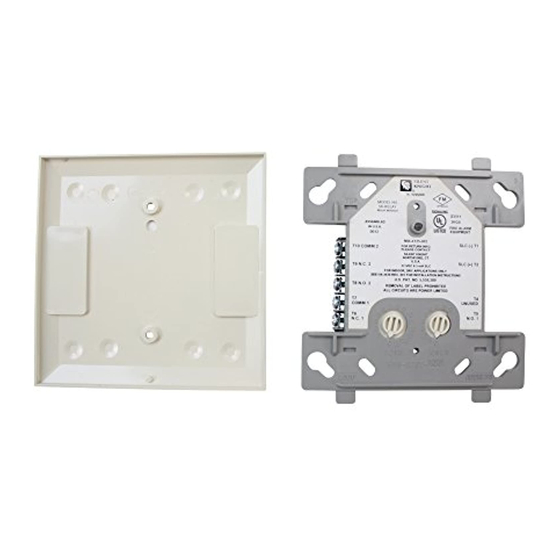
fIgURE 1. CONTROLS AND INDICATORS:
SK-470-001
15 to 32 VDC
6.5 mA (LED on)
230μA direct poll; 255μA group poll
Not used
32˚F to 120˚F (0˚C to 49˚C)
10% to 93% Non-condensing
4
1
/
˝ H × 4˝ W × 1
1
/
˝ D (Mounts to a 4˝ square by 2
2
4
SMB500 Electrical Box
C1071-00
1
/
˝ deep box.)
8
MOUNTINg
The SK-Relay mounts directly to 4-inch square electrical boxes (see Figure
2A). The box must have a minimum depth of 2
electrical boxes (SMB500) are available from Silent Knight.
fIgURE 2A. MODULE MOUNTINg
wITh BARRIER:
wIRINg
NOTE: All wiring must conform to applicable local codes, ordinances, and reg-
ulations. When using control modules in nonpower limited applications, the
CB500 Module Barrier must be used to meet UL requirements for the separa-
tion of power-limited and nonpower-limited terminals and wiring. The barrier
must be inserted into a 4˝ × 4˝ × 2
must be placed into the barrier and attached to the junction box (Figure 2A).
The power-limited wiring must be placed into the isolated quadrant of the
module barrier (Figure 2B).
1.
Install module wiring in accordance with the job drawings and appropri-
ate wiring diagrams.
2.
Set the address on the module per job drawings.
3.
Secure module to electrical box (supplied by installer), as shown in
Figure 2A.
1
12 Clintonville Road, Northford, CT 06472
203.484.7161; Fax: 203.484.7118
www.silentknight.com
1
/
inches. Surface mounted
8
fIgURE 2B:
1
/
˝ junction box, and the control module
8
I56-3438-001
C1070-00
Advertisement

Related Manuals for Honeywell Silent Knight SK-Relay


Summary of Contents for Honeywell Silent Knight SK-Relay
- Page 1 INSTALLATION AND MAINTENANCE INSTRUCTIONS 12 Clintonville Road, Northford, CT 06472 203.484.7161; Fax: 203.484.7118 SK-Relay www.silentknight.com SpECIfICATIONS Normal Operating Voltage: 15 to 32 VDC Maximum Current Draw: 6.5 mA (LED on) Average Operating Current: 230μA direct poll; 255μA group poll EOL Resistance: Not used Temperature Range: 32˚F to 120˚F (0˚C to 49˚C)
- Page 2 INFORMATION ON THE NAMEPLATE LABEL. MODULE DOES NOT SUPERVISE CONTROLLED CIRCUITS *NOTE: ANY FAULT IN THE POWER SUPPLY IS LIMITED TO THAT ZONE AND DOES NOT RESULT IN A FAULT IN A SEPARATE ZONE. C0946-00 SK-470-001 I56-3438-001 ©2009 Honeywell International Inc.