Advertisement
Quick Links
For questions or help with this product contact Tech Support at (570) 546-9663 or techsupport@grizzly.com
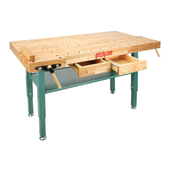
Figure 1. Model T10157 Oak Workbench.
Features
•
Solid 1
⁄
" thick oak top with double rows of
1
2
bench dog holes for each vise.
•
Two storage drawers (with ball bearing slides)
that are 12
⁄
" wide x 12
7
8
•
Sturdy adjustable steel legs with leveling foot
pads.
•
Two oak-faced vises with 4" leadscrew travel,
13" wide x 2" thick, and one removable top
plate.
•
Four bench dogs and a bench stop bar.
•
All wood surfaces finished with durable lac-
quer.
•
Overall dimensions: 62" wide x 30" in depth x
32"–39" tall.
•
Weight: 110 lbs.
COPYRIGHT © OCTOBER, 2008 BY GRIZZLY INDUSTRIAL, INC., REVISED JUNE, 2022 (CS)
WARNING: NO PORTION OF THIS MANUAL MAY BE REPRODUCED IN ANY SHAPE
OR FORM WITHOUT THE WRITTEN APPROVAL OF GRIZZLY INDUSTRIAL, INC.
(FOR MODELS MANUFACTURED SINCE 07/19) #TS11313 PRINTED IN CHINA
⁄
" long x 2
⁄
" deep.
9
13
16
16
***Keep for Future Reference***
MODEL T10157
HEAVY-DUTY OAK
WORKBENCH w/STEEL LEGS
INSTRUCTIONS
Wear safety glasses during
the entire setup process!
Straining or crushing injury
may occur from improperly
lifting machine or some of
its parts. To reduce this risk,
get help from other people
and use a forklift (or other
lifting equipment) rated for
weight of this machine.
HEAVY LIFT!
V4.06.22
Advertisement

Related Manuals for Grizzly T10157


Summary of Contents for Grizzly T10157
- Page 1 MODEL T10157 HEAVY-DUTY OAK WORKBENCH w/STEEL LEGS INSTRUCTIONS For questions or help with this product contact Tech Support at (570) 546-9663 or techsupport@grizzly.com Wear safety glasses during the entire setup process! HEAVY LIFT! Straining or crushing injury may occur from improperly lifting machine or some of its parts.
-
Page 2: Table Of Contents
W. Wood Screws #8 x 1" ....... 20 NOTICE If you cannot find an item on this list, check the mounting location on the workbench or examine the packaging materials carefully. Figure 2. Inventory. Some items are pre-installed for shipping purposes. Model T10157 (Mfd. Since 07/19) - Page 3 Hardware Recognition Chart USE THIS CHART TO MATCH UP HARDWARE DURING THE INVENTORY AND ASSEMBLY PROCESS. Flat Head Screw Model T10157 (Mfd. Since 07/19)
-
Page 4: Bottom Drawer Panels
Back Drawer Panel back of drawer. Figure 6. Installing back drawer panel. Install (2) wood dowels in holes of back drawer panel. Tapered End Figure 4. Tapered end of drawer slide (right drawer panel shown). Model T10157 (Mfd. Since 07/19) -
Page 5: Left Drawer Panels
Note: Make sure that completed leg assem- blies are all same length, which will dictate height of finished workbench (from 32"–39"). Upper Lower Figure 8. Securing bottom drawer panel to back drawer panel. Figure 10. Upper and lower leg. Model T10157 (Mfd. Since 07/19) -
Page 6: Workbench Top
Note: In next step, take care to properly ori- ent leadscrew holes in leg assemblies with Drawer Support holes in workbench top to accept vise lead- Assembly screws in later step (see Figure 13). Figure 14. Installing drawer support assemblies. Model T10157 (Mfd. Since 07/19) -
Page 7: Bench Stop Bar
Figure 16. Note: Left and right drawers are different. If Note: You can install shelf with lip facing up they do not fit, switch their positions. or down. Bottom Shelf Figure 16. Bottom shelf installed. Model T10157 (Mfd. Since 07/19) - Page 8 PT10157037 WOOD SCREW #10 X 1-1/2 PT10157020 UPPER LEG W/SIDE LEADSCREW HOLE PT10157039 RIGHT DRAWER SUPPORT W/BB SLIDE 20-1 PT10157020-1 UPPER LEG W/FRONT LEADSCREW HOLE PT10157040 CENTER DRAWER SUPPORT W/BB SLIDE PT10157021 LOWER LEG PT10157035V2 Model T10157 (Mfd. Since 07/19)