
Related Manuals for GE PACSystems RXi Box IPC


Summary of Contents for GE PACSystems RXi Box IPC
- Page 1 Intelligent Platforms Industrial Computer Products PACSystems* RXi Box IPC User's Manual, GFK-2785C May 2014...
- Page 2 No warranties of merchantability or fitness for purpose shall apply. * indicates a trademark of GE Intelligent Platforms, Inc. and/or its affiliates. All other trademarks are the property of their respective owners. ©Copyright 2014 GE Intelligent Platforms, Inc.
- Page 3 Contact Information If you purchased this product through an Authorized Channel Partner, please contact the seller directly. General Contact Information Online technical support and GlobalCare http://support.ge-ip.com Additional information http://www.ge-ip.com/ Solution Provider solutionprovider.ip@ge.com Technical Support If you have technical problems that cannot be resolved with the information in this guide, please contact us by telephone or email, or on the web at http://support.ge-ip.com...
-
Page 4: Table Of Contents
Contents Contents Introduction ............................1 Specifications ..........................2 General Specifications ........................ 2 Environmental Specifications ..................... 3 RXi Box IPC User Features ......................4 Power On/Off Switch and Status Indicator Operation..............5 IPC Status Indicators Operation ....................5 Ethernet Port LEDs Operation ....................5 Resume Power Mode Operation .................... -
Page 6: Introduction
Introduction The PACSystems RXi family of industrial computers provides an advanced, high-performance control and computing platform. The PACSystems RXi Box IPC delivers the flexibility of a PC with the industrial ruggedness of traditional automation controllers. Built with an open and scalable architecture, the RXi platform enables easy connectivity and allows you to maximize application reusability—supporting your current and future needs for... -
Page 7: Specifications
Introduction Specifications Part numbers: ICRXIBN7E000A RXi Box IPC with Embedded 32GB mSATA SSD and Windows 7 Professional, SP1 or later operating system ICRXIBN7E001A RXi Box IPC with Embedded 32GB mSATA SSD and Windows Embedded Standard 7 ICRXIBN7M000A RXi Box IPC with 250GB Magnetic SATA Hard Drive and Windows 7 Professional, SP1 or later operating system ICRXIBN7M001A RXi Box IPC with 250GB Magnetic SATA Hard Drive and Windows Embedded... -
Page 8: Environmental Specifications
Introduction Environmental Specifications Note: The Box IPC shall be installed in a location that is not exposed to corrosive gases or liquids, rain, or direct sunlight, and that meets the environmental specifications listed below. Vibration IEC60068-2-6 10 - 57 Hz, 0.006 in. displacement peak-peak 57 - 500 Hz, 1.0 g acceleration IEC60068-2-27 Shock... -
Page 9: Rxi Box Ipc User Features
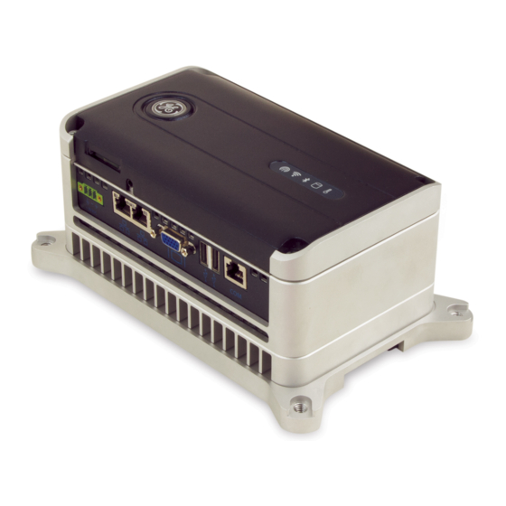
Introduction RXi Box IPC User Features Power On/Off Audio Indicators Switch and Status Connector Indicator SD Card Slot Blue, blinking – Booting Blue, slow fade – S3 Sleep – Running Green, solid – Fault Red, solid Connectors PACSystems* RXi Box IPC GFK-2785C... -
Page 10: Power On/Off Switch And Status Indicator Operation
Introduction Power On/Off Switch and Status Indicator Operation † Normal Operation Action Power up the IPC Press and hold the button for at least ½ second. If powering up from a no-power state, the ring LED blinks blue while the IPC is booting and is solid green when the IPC is up and running. -
Page 11: Resume Power Mode Operation
Introduction Resume Power Mode Operation UEFI Setting for “Resume ICRXIBN7x001A RXi Box IPC Behavior after Power loss” [On - default] After restoring power, the unit will always restart without having to press the button. [Off] After restoring power, you will always have to press the button to start the unit. -
Page 12: Unpacking And Initial Startup
If damage is observed (for example, in the form of bent component leads or loose components), contact GE Intelligent Platforms for additional instructions. Depending on the severity of the damage, it may be necessary to return the product to the factory for repair. -
Page 13: Initial Startup
Unpacking and Initial Startup Initial Startup You will need the following: 24VDC, 18–32V range, 48W power supply, Class 2 or LPS The product is supplied with a Phoenix Contact part number 1827716 or 1851245 (spring loaded/quick release) power terminal block for use with a power supply. The power supply used must be a UL Listed (or equivalent) Limited Power Source (LPS) or Class 2 power source. -
Page 14: Configuring Ethernet Network Communications
Unpacking and Initial Startup 8. To activate the operating system online, you will need to first configure the IPC’s Ethernet settings for operation on your network. Note: The ICRXIBN0E000A and ICRXIBN0M000A models come with two hard drive options: a blank 32GB mSATA solid state drive or a blank 250GB SATA magnetic hard drive. You will need to load the desired operating system and associated drivers to fully utilize the I/O interfaces. -
Page 15: Shutting Down The Computer
Unpacking and Initial Startup 1. Disconnect your industrial computer from the LAN. 2. Ping the disconnected industrial computer’s IP address. If you get an answer to the ping, the chosen IP address is already in use by another node. You must correct this situation by assigning a unique IP address. -
Page 16: Hardware Installation
Hardware Installation Chapter This chapter describes the procedures for the safe location and securing of the RXi Box IPC. Note: The proper method for removing power from the unit is to switch off power at the circuit breaker. Installation Guidelines The RXi Box IPC can be mounted on a DIN rail using the optional Backplate (ICRXIACCBPL) or directly onto a panel. -
Page 17: Grounding
Hardware Installation Grounding Note: These grounding connections serve as a path for reducing noise interference and radiated emissions and are required for the IPC to comply with the standards identified in Appendix A. The DIN rail or panel the IPC is mounted on must have a safety ground connection to protective earth. -
Page 18: Dimensions And Clearances For Installation
Hardware Installation Dimensions and Clearances for Installation Dimensions IPC: 191.8 mm x 115.6 mm x 81.3 mm (7.55 in x 4.55 in. x 3.2 in) Backplate: 226 mm x 137 mm x 12 mm (8.90 in. x 5.39 in. x 0.47 in.) Minimum clearances for heat dissipation Each side: 51mm (2 inches) -
Page 19: Mounting Procedures
Hardware Installation Mounting Procedures Using the optional ICRXIACCBPL Backplate, the IPC can be mounted on a DIN rail or a panel. You can also mount the IPC directly onto a panel without using a Backplate. The IPC has four captive machine screws in its base for attaching the unit to the Backplate or panel. - Page 20 Hardware Installation 1. Install the IPC on the Backplate. Place the IPC and Backplate on a flat surface. b. Loosen the four captive screws on the IPC’s front panel and remove the front panel. GFK-2785C PACSystems* RXi Box IPC...
- Page 21 Hardware Installation Make sure the top of the IPC is positioned at the top of the Backplate (static latches on top). For Backplate orientation, refer to page 14. d. Align the IPC’s four mounting screws with the mounting holes in the Backplate. Using the hex driver, tighten the mounting screws.
- Page 22 Hardware Installation 2. Install the unit on the DIN Rail. Start with the top of the unit rotated approximately 20º from the panel. b. Engage the spring-loaded latches at the bottom of the black DIN rail clip (attached to the adaptor) on the DIN rail.
-
Page 23: Mounting The Ipc On A Panel Using A Backplate
Hardware Installation Mounting the IPC on a Panel Using a Backplate You will need the following: Four machine screws with maximum thread size ¼-20 (standard) or M6 (metric) Driver for selected machine screws One ICRXIACCBPL Backplate 1. Install the IPC on the Backplate. (See step 1 on page 14.) 2. -
Page 24: Mounting The Ipc Directly On A Panel
Hardware Installation Mounting the IPC Directly on a Panel You will need the following: One flathead (or large Phillips) screwdriver One 2.5mm hex driver (included with the RXi IPC) #29 (0.116”) drill bit and M4x0.7 tap The IPC has four captive machine screws in its base for attaching the unit to the panel. 1. - Page 25 Hardware Installation 4. Align the IPC’s four mounting screws with the mounting holes in the panel. 5. Using the hex driver, hand-tighten the mounting screws. 6. Replace the front panel on the IPC and hand-tighten the four screws to secure it. PACSystems* RXi Box IPC GFK-2785C...
-
Page 26: Replacing The Rtc Battery
Hardware Installation Replacing the RTC Battery The real-time clock is backed up by a lithium coin cell battery, IC690ACC001. The RTC battery has an estimated life of 5 years and must be replaced every 5 years on a regular maintenance schedule. - Page 27 For proper disposal, refer to Battery Disposal document 82A1540-MD01. 6. Install the new battery in the retaining clip. The replacement battery must be IC690ACC001 from GE Intelligent Platforms. Install the battery with the positive (+) side up. That is, with the + side away from the circuit board.
-
Page 28: Disabling The Off Switch
Hardware Installation Disabling the Off Switch You can disable powering off using the On/Off switch by changing the setting of SW1-1, located on the underside of the IPC’s front panel. This prevents unplanned shutdowns caused by accidentally pressing the On/Off switch. The disabled setting affects only the ability to power down the unit. - Page 29 Hardware Installation PACSystems* RXi Box IPC GFK-2785C...
-
Page 30: Connectors And Cabling
Chapter Connectors and Cabling This chapter describes the connector layout and cabling requirements on the RXi box IPC. Power and communication connectors are described in this section. All connectors are provided on the bottom panel of the IPC. Summary of Cabled Ports Port Name Usage Maximum Cable Length... -
Page 31: Ethernet Communication Ports
Connectors and Cabling Ethernet Communication Ports ACTIVITY LINK The IPC provides two RJ-45 Ethernet network port connectors that support 10BASE-T, 100BASE-TX and 1000BASE-T communications. Either or both of these ports may be attached to other Ethernet devices. Each port automatically senses the data rate (10, 100 or 1000Mbps), duplex (half duplex or full duplex), and cabling Pin 1 arrangement (straight through or crossover) of the... -
Page 32: Serial Communication Port
Connectors and Cabling Serial Communication Port The serial port provides RS-232 communications through a standard RJ-45 female connector with the following pin assignments. For maximum cable length, refer to page 25. RS-232 Serial Port Pin Assignments RJ-45 Signal Description No connection No connection No connection Receive... -
Page 33: Video Output Port
Connectors and Cabling Video Output Port Video monitor output is provided on the standard 15-pin VGA connector. The pin assignments are shown in the following table. Shielded cable is required. For maximum cable length, refer to page 25. Video Pin Assignments GREEN BLUE Red GND... -
Page 34: System Recovery
To re-install the Windows 7 Professional operating system, refer to http://windows.microsoft.com for instructions. RXi Box IPC Device Drivers The drivers and the instructions for installing them are available on the GE Intelligent Platforms Support website, http://support.ge-ip.com. The drivers consist of: ... -
Page 35: Recovering From A Drive Failure (Icrxibn7X001X Models Only)
System Recovery Recovering from a Drive Failure (ICRXIBN7x001x Models only) A USB Drive is shipped along with the Windows Embedded Standard 7IPC unit. Retain it in a secure location. Use this drive to recover in the event of drive failure. The procedure is as follows: 1. - Page 36 System Recovery 4. The RXi will boot to the Window PE (WinPE) on the USB drive. This will take a minute. Wait for the RXi recovery screen to appear. 5. Click the ‘Start WES7 Recovery’ button. Note: clicking the ‘Exit the Program’ button will abort the recovery and reboot the RXi computer.
- Page 37 System Recovery 7. The image load process will be displayed as follows: 8. When the image load completes, the system will prompt to remove the USB drive: 9. Remove the USB drive and click OK. The system will reboot as a new factory install. PACSystems* RXi Box IPC GFK-2785C...
-
Page 38: Recovering From An Overtemperature Shutdown (All Models)
System Recovery Recovering from an Overtemperature Shutdown (All Models) If the Box IPC overheats, it will shut down to protect critical components. When this happens, the Overtemp LED will blink on red and then shut off quickly while the entire unit shuts down. The Power On/Off LED turns off at the same time. - Page 39 System Recovery PACSystems* RXi Box IPC GFK-2785C...
-
Page 40: Product Certifications And Installation Guidelines For Conformance
Appendix Product Certifications and Installation Guidelines for Conformance This appendix describes the compliance markings that appear on PACSystems RXi industrial computer products and the corresponding standards to which the products have been certified. GFK-2785C PACSystems* RXi Box IPC... -
Page 41: Agency Approvals
CSA 60950-1 Low Voltage Directive Self-Declaration in accordance with European Directives; Refer to Declaration of Conformity European Safety for Industrial Control found at http://www.ge-ip.com/ for a complete Equipment list of approved products Electromagnetic Compatibility Self-Declaration in accordance with European Directive Directives;... -
Page 42: Standards Overview
Product Certifications and Installation Guidelines for Conformance Standards Overview For environmental specifications, refer to chapter 1. EMC Emissions and Immunity Specifications EMC EMISSIONS Emissions CISPR 11/EN 55011/ 30 – 1000 MHz, radiated, Group 1, Class A, EN55016-2-3 FCC 47CFR15 30 – 7500 MHz, radiated, Class A CISPR 22/EN55022 30 –... -
Page 43: Government Regulations
Note: Changes or modifications to this unit that are not expressly approved by GE Intelligent Platforms could void the user’s authority to operate the equipment. -
Page 44: Index
Index Air flow, 11 dimensions, 13 Audio jack, 28 DIN rail, 14 Battery, real time clock (RTC), 21 orientation, 12 Clearances, 13 panel, direct, 19 Connectors panel, with a Backplate, 18 audio jack, 28 space required, 13 Ethernet, 26 Network communications overview, 4 configuration, 9 power, 8, 25...